EP4553379A1 - Dispositif de blocage et lampe de véhicule - Google Patents
Dispositif de blocage et lampe de véhicule Download PDFInfo
- Publication number
- EP4553379A1 EP4553379A1 EP23834874.2A EP23834874A EP4553379A1 EP 4553379 A1 EP4553379 A1 EP 4553379A1 EP 23834874 A EP23834874 A EP 23834874A EP 4553379 A1 EP4553379 A1 EP 4553379A1
- Authority
- EP
- European Patent Office
- Prior art keywords
- blocking
- light
- state
- sheet
- assemblies
- Prior art date
- Legal status (The legal status is an assumption and is not a legal conclusion. Google has not performed a legal analysis and makes no representation as to the accuracy of the status listed.)
- Pending
Links
Images


Classifications
-
- F—MECHANICAL ENGINEERING; LIGHTING; HEATING; WEAPONS; BLASTING
- F21—LIGHTING
- F21V—FUNCTIONAL FEATURES OR DETAILS OF LIGHTING DEVICES OR SYSTEMS THEREOF; STRUCTURAL COMBINATIONS OF LIGHTING DEVICES WITH OTHER ARTICLES, NOT OTHERWISE PROVIDED FOR
- F21V14/00—Controlling the distribution of the light emitted by adjustment of elements
- F21V14/006—Controlling the distribution of the light emitted by adjustment of elements by means of optical elements, e.g. films, filters or screens, being rolled up around a roller
-
- F—MECHANICAL ENGINEERING; LIGHTING; HEATING; WEAPONS; BLASTING
- F21—LIGHTING
- F21S—NON-PORTABLE LIGHTING DEVICES; SYSTEMS THEREOF; VEHICLE LIGHTING DEVICES SPECIALLY ADAPTED FOR VEHICLE EXTERIORS
- F21S41/00—Illuminating devices specially adapted for vehicle exteriors, e.g. headlamps
- F21S41/50—Illuminating devices specially adapted for vehicle exteriors, e.g. headlamps characterised by aesthetic components not otherwise provided for, e.g. decorative trim, partition walls or covers
-
- B—PERFORMING OPERATIONS; TRANSPORTING
- B60—VEHICLES IN GENERAL
- B60Q—ARRANGEMENT OF SIGNALLING OR LIGHTING DEVICES, THE MOUNTING OR SUPPORTING THEREOF OR CIRCUITS THEREFOR, FOR VEHICLES IN GENERAL
- B60Q1/00—Arrangement of optical signalling or lighting devices, the mounting or supporting thereof or circuits therefor
- B60Q1/02—Arrangement of optical signalling or lighting devices, the mounting or supporting thereof or circuits therefor the devices being primarily intended to illuminate the way ahead or to illuminate other areas of way or environments
- B60Q1/04—Arrangement of optical signalling or lighting devices, the mounting or supporting thereof or circuits therefor the devices being primarily intended to illuminate the way ahead or to illuminate other areas of way or environments the devices being headlights
- B60Q1/14—Arrangement of optical signalling or lighting devices, the mounting or supporting thereof or circuits therefor the devices being primarily intended to illuminate the way ahead or to illuminate other areas of way or environments the devices being headlights having dimming means
- B60Q1/1438—Actuating means for dimming masks or screens
-
- F—MECHANICAL ENGINEERING; LIGHTING; HEATING; WEAPONS; BLASTING
- F16—ENGINEERING ELEMENTS AND UNITS; GENERAL MEASURES FOR PRODUCING AND MAINTAINING EFFECTIVE FUNCTIONING OF MACHINES OR INSTALLATIONS; THERMAL INSULATION IN GENERAL
- F16H—GEARING
- F16H1/00—Toothed gearings for conveying rotary motion
- F16H1/28—Toothed gearings for conveying rotary motion with gears having orbital motion
-
- F—MECHANICAL ENGINEERING; LIGHTING; HEATING; WEAPONS; BLASTING
- F21—LIGHTING
- F21S—NON-PORTABLE LIGHTING DEVICES; SYSTEMS THEREOF; VEHICLE LIGHTING DEVICES SPECIALLY ADAPTED FOR VEHICLE EXTERIORS
- F21S43/00—Signalling devices specially adapted for vehicle exteriors, e.g. brake lamps, direction indicator lights or reversing lights
- F21S43/20—Signalling devices specially adapted for vehicle exteriors, e.g. brake lamps, direction indicator lights or reversing lights characterised by refractors, transparent cover plates, light guides or filters
- F21S43/235—Light guides
- F21S43/236—Light guides characterised by the shape of the light guide
- F21S43/239—Light guides characterised by the shape of the light guide plate-shaped
-
- F—MECHANICAL ENGINEERING; LIGHTING; HEATING; WEAPONS; BLASTING
- F21—LIGHTING
- F21S—NON-PORTABLE LIGHTING DEVICES; SYSTEMS THEREOF; VEHICLE LIGHTING DEVICES SPECIALLY ADAPTED FOR VEHICLE EXTERIORS
- F21S43/00—Signalling devices specially adapted for vehicle exteriors, e.g. brake lamps, direction indicator lights or reversing lights
- F21S43/20—Signalling devices specially adapted for vehicle exteriors, e.g. brake lamps, direction indicator lights or reversing lights characterised by refractors, transparent cover plates, light guides or filters
- F21S43/235—Light guides
- F21S43/242—Light guides characterised by the emission area
- F21S43/245—Light guides characterised by the emission area emitting light from one or more of its major surfaces
-
- F—MECHANICAL ENGINEERING; LIGHTING; HEATING; WEAPONS; BLASTING
- F21—LIGHTING
- F21S—NON-PORTABLE LIGHTING DEVICES; SYSTEMS THEREOF; VEHICLE LIGHTING DEVICES SPECIALLY ADAPTED FOR VEHICLE EXTERIORS
- F21S43/00—Signalling devices specially adapted for vehicle exteriors, e.g. brake lamps, direction indicator lights or reversing lights
- F21S43/20—Signalling devices specially adapted for vehicle exteriors, e.g. brake lamps, direction indicator lights or reversing lights characterised by refractors, transparent cover plates, light guides or filters
- F21S43/255—Filters
-
- F—MECHANICAL ENGINEERING; LIGHTING; HEATING; WEAPONS; BLASTING
- F21—LIGHTING
- F21S—NON-PORTABLE LIGHTING DEVICES; SYSTEMS THEREOF; VEHICLE LIGHTING DEVICES SPECIALLY ADAPTED FOR VEHICLE EXTERIORS
- F21S43/00—Signalling devices specially adapted for vehicle exteriors, e.g. brake lamps, direction indicator lights or reversing lights
- F21S43/50—Signalling devices specially adapted for vehicle exteriors, e.g. brake lamps, direction indicator lights or reversing lights characterised by aesthetic components not otherwise provided for, e.g. decorative trim, partition walls or covers
-
- F—MECHANICAL ENGINEERING; LIGHTING; HEATING; WEAPONS; BLASTING
- F21—LIGHTING
- F21S—NON-PORTABLE LIGHTING DEVICES; SYSTEMS THEREOF; VEHICLE LIGHTING DEVICES SPECIALLY ADAPTED FOR VEHICLE EXTERIORS
- F21S43/00—Signalling devices specially adapted for vehicle exteriors, e.g. brake lamps, direction indicator lights or reversing lights
- F21S43/601—Signalling devices specially adapted for vehicle exteriors, e.g. brake lamps, direction indicator lights or reversing lights characterised by variable optical properties, e.g. involving the use of LCD or movable parts
-
- F—MECHANICAL ENGINEERING; LIGHTING; HEATING; WEAPONS; BLASTING
- F21—LIGHTING
- F21S—NON-PORTABLE LIGHTING DEVICES; SYSTEMS THEREOF; VEHICLE LIGHTING DEVICES SPECIALLY ADAPTED FOR VEHICLE EXTERIORS
- F21S45/00—Arrangements within vehicle lighting devices specially adapted for vehicle exteriors, for purposes other than emission or distribution of light
- F21S45/10—Protection of lighting devices
-
- F—MECHANICAL ENGINEERING; LIGHTING; HEATING; WEAPONS; BLASTING
- F21—LIGHTING
- F21W—INDEXING SCHEME ASSOCIATED WITH SUBCLASSES F21K, F21L, F21S and F21V, RELATING TO USES OR APPLICATIONS OF LIGHTING DEVICES OR SYSTEMS
- F21W2107/00—Use or application of lighting devices on or in particular types of vehicles
- F21W2107/10—Use or application of lighting devices on or in particular types of vehicles for land vehicles
Definitions
- the present application relates to the technical field of vehicle manufacturing, and in particular to a blocking device and a vehicle lamp.
- a light-emitting assembly of a vehicle lamp is usually protected only by a lamp shade covering the light-emitting assembly, and the light-emitting assembly is easily damaged (for example, the light-emitting assembly may be damaged when the vehicle lamp collides with a splashing object during driving) .
- a blocking device is usually provided in front of the light-emitting assembly to block and protect the light-emitting assembly when the light-emitting assembly is not in operation.
- the part of the blocking device for blocking the light-emitting assembly needs to be hidden by a transmission part, to expose light-emitting assembly.
- the part of the blocking device still remains unhidden.
- the part of the blocking device appears incompletely, resulting in that a part of the light-emitting assembly is still not blocked by the blocking device.
- An object of the present application is to provide a blocking device and a vehicle lamp, to solve the technical problem in the prior art that it is difficult to control the accuracy of the movement stroke of the part of the existing blocking device in a blocking process (or an appearing process), often resulting in incomplete hiding (or incomplete appearance) of the part of the blocking device.
- a blocking device for blocking a light-emitting assembly having a light path direction.
- the blocking device is arranged in front of the light-emitting assembly in the light path direction.
- the blocking device includes a transmission part and multiple blocking assemblies, the transmission part includes transmission teeth, and each of the multiple blocking assemblies includes meshing teeth, and the transmission teeth are meshed with the meshing teeth to drive the corresponding blocking assembly to switch between a first state and a second state;
- the transmission teeth are embodied as an inner toothed ring.
- Each of the multiple blocking assemblies includes a rotary shaft, and the meshing teeth of the blocking assembly are embodied as a rotary gear, the rotary gear and the rotary shaft are coaxially arranged; the rotary gear is meshed with the inner toothed ring to drive the blocking assembly to rotate with the rotary shaft, to make the blocking assembly be switched between the first state and the second state.
- each of the multiple blocking assemblies includes a blocking sheet
- the rotary shaft is provided on one side of the blocking sheet proximate to the inner toothed ring
- the blocking body is in a circular shape as viewed in the light path direction, and the blocking sheets of the multiple blocking assemblies are uniformly distributed in a circumferential direction of the circular shape.
- the transmission part further includes driving teeth
- the blocking device further includes a driving assembly
- the driving assembly is meshed with the driving teeth
- the transmission part is an annular washer
- the inner toothed ring is provided on an inner ring of the annular washer
- the driving teeth are provided on at least part of an outer ring of the annular washer.
- each of the multiple blocking assemblies includes a guide post, and the guide post is provided on the other side of the blocking sheet; and the blocking device further includes a guide part having a guide groove, the guide post is arranged in the guide groove; and the guide post is configured to slide along the guide groove when the blocking assembly is being switched between the first state and the second state.
- the blocking device further includes a first receiving part having a channel portion and an annulus portion being connected to each other.
- the channel portion includes a cylindrical channel
- the light-emitting assembly is arranged at one end of the cylindrical channel
- the cylindrical channel has an axis coinciding with an axis of the blocking body.
- the annulus portion is arranged between the transmission part and the multiple blocking assemblies, and the rotary shaft runs through the annulus portion.
- the blocking device further includes a second receiving part being in an annular shape, and the second receiving part is sleeved outside the channel portion.
- the second receiving part is arranged on one side of the transmission part away from the multiple blocking assemblies, one end of the rotary shaft is connected to the second receiving part, and the other end of the rotary shaft is connected to the blocking sheet.
- the blocking device further includes projecting parts, and each of the blocking assemblies includes a corresponding one of the projecting parts, and the projecting part is provided on one edge of the blocking sheet away from a center of the circular shape;
- a vehicle lamp is provided according to a second aspect of the present application, the vehicle lamp includes the blocking device according to any one of the above technical solutions, and thus the vehicle lamp has all the beneficial effects of the blocking device, which will not be described in detail here.
- the vehicle lamp further includes the light-emitting assembly, and the vehicle lamp can be switched among a resting state, a side-projecting state and a front-projecting state when the blocking assemblies are in the first state;
- the transmission teeth are in meshing cooperation with the meshing teeth, thus the accuracy of transmission between the multiple blocking assemblies and the transmission part is improved when the transmission part drives the multiple blocking assemblies to switch between the first state and the second state, so that movement strokes of the multiple blocking assemblies are controllable, thereby effectively preventing incomplete blocking and incomplete exposure.
- the terms “mount”, “connected to” and “connection” should be understood in a broad sense. For example, it may refer to a fixed connection, a detachable connection, or an integral connection; it may refer to a mechanical connection, or an electrical connection; it may refer to a direct connection, or an indirect connection through an intermediate medium, or internal communication between two elements.
- the specific meanings of the above terms in the present application may be understood according to specific situations.
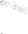
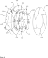
- a blocking device and a vehicle lamp according to some embodiments of the present application will be described below with reference to FIG. 1 to FIG. 4 .
- a blocking device for blocking a light-emitting assembly 800 having a light path direction is provided according to an embodiment of the present application, and the light-emitting assembly 800 is arranged in front of the light-emitting assembly 800 in the light path direction.
- the blocking device includes a transmission part 200 and multiple blocking assemblies, where the transmission part 200 includes transmission teeth, each of the multiple blocking assemblies includes meshing teeth, and the transmission teeth are meshed with the meshing teeth to drive the corresponding blocking assembly to switch between a first state and a second state.
- the multiple blocking assemblies are fitted together to form a blocking body, to make at least part of the light-emitting assembly 800 be blocked by the blocking body as viewed in the light path direction.
- the transmission part 200 is configured to drive the multiple blocking assemblies to be separated from each other, to make the light-emitting assembly 800 be exposed as viewed in the light path direction.
- the accuracy of transmission between the multiple blocking assemblies and the transmission part 200 is improved when the transmission part 200 drives the blocking assemblies to switch between the first state and the second state, so that movement strokes of the multiple blocking assemblies are controllable, thereby effectively preventing incomplete blocking and incomplete exposure by the blocking device.
- the transmission teeth may be an inner toothed ring 210.
- the blocking assembly includes a rotary shaft 120, and the meshing teeth are embodied as a rotary gear 130 coaxially arranged with the rotary shaft 120.
- the rotary gear 130 is meshed with the inner toothed ring 210 to drive the blocking assembly to rotate with the rotary shaft 120, such that the blocking assembly is switched between the first state and the second state.
- the transmission part 200 may further include driving teeth 220
- the blocking device may further include a driving assembly 300
- the driving assembly 300 is meshed with the driving teeth 220 to drive the transmission part 200 to move.
- the transmission part 200 may be an annular washer.
- the inner toothed ring 210 may be provided on an inner ring of the annular washer, and the driving teeth 220 are provided on at least part of an outer ring of the annular washer.
- the driving assembly 300 can mesh with the driving teeth 220 to drive the annular washer to rotate around its own axis, to further drive the rotary gear 130 to rotate.
- the driving assembly 300 may include a rotary motor and a driving gear coaxially arranged with each other, and the driving gear meshes with the driving teeth 220 to realize transmission.
- the driving assembly is not limited to the form of the above rotary motor and the driving gear.
- the driving assembly may be in other forms as long as it can mesh with the driving teeth to provide power for the inner toothed ring.
- the driving assembly may include a worm and a linear driving portion, where the worm is meshed with the driving teeth, and the linear driving portion is connected to one end of the worm.
- the linear driving portion may be a pneumatic cylinder, a linear motor or the like.
- the driving assembly may further include the linear driving portion, an annular gear and a lead screw, where the linear drive portion is connected to one end of the lead screw, an inner ring of the annular gear is formed with internal threads engaged with the lead screw, the annular gear is meshed with the above driving teeth, and the annular gear is sleeved outside the lead screw.
- each blocking assembly includes a blocking sheet 110, and the rotary shaft 120 is provided on one side of the blocking sheet 110 proximate to the inner toothed ring 210.
- the blocking body When viewed in the light path direction, the blocking body is in a circular shape, and the blocking sheets 110 of the multiple blocking assemblies are uniformly distributed in a circumferential direction of the circular shape.
- the light-emitting assembly 800 can be gradually exposed from a center of the blocking body, so that a hidden process of the blocking assemblies forms a dynamic effect of the light-emitting assembly 800 gradually blooming from the center.
- the light-emitting assembly 800 can be gradually blocked from an edge of the blocking body, so that an appearance process of the blocking assembly forms a dynamic effect of the light-emitting assembly 800 gradually closing and converging from the edge, thus the exposure/hidden process of the light-emitting assembly 800 has a more cool and technological sense, which effectively improves the advanced sense of the vehicle lamp, thereby improving the user experience.
- one of the blocking assemblies is concealed in the drawing.
- a width of the blocking sheet 110 gradually decreases from the edge of the blocking body to the center of the blocking body, such that the multiple blocking sheets 110 can be fitted together to form the circular blocking body.
- the blocking sheet 110 when being viewed along the light path direction, is of a shape formed by three segments of arcs connected end to end.
- the arc formed by an edge of the blocking sheet 110 extending in the circumferential direction of the blocking body is defined as a first arc 111, and the other two arcs are defined as a second arc 112 and a third arc 113, respectively.
- a sharp corner defined by the first arc 111 and the third arc 113 is referred to as a first sharp corner 115
- a sharp corner defined by the second arc 112 and the third arc 113 is referred to as a second sharp corner 116
- a sharp corner defined by the first arc 111 and the second arc 112 is referred to as a third sharp corner 117.
- the above rotary shaft 120 is arranged at the first sharp corner 115.
- the second arc 112 is formed by making an arc with the rotary shaft 120 as an axis and a distance from an end of the second sharp corner 116 to the rotary shaft 120 as a radius.
- the third arc 113 is configured to be fitted to the second arc 112 of another blocking sheet 110 which is adjacent to the above blocking sheet 110 and located at a side of the above blocking sheet 110 where the third arc 113 is, so as to effectively prevent the blocking sheet 110 from interfering with adjacent blocking sheets 110 during rotation.
- the blocking sheet 110 further includes an extension edge 114, which is provided at the edge of the blocking sheet 110 where the third arc 113 is located.
- the extension edge 114 can effectively fill a gap between two adjacent blocking sheets 110, to prevent incomplete blocking for the light-emitting assembly 800 when the blocking assemblies are in the first state.
- each of the blocking assemblies includes v a guide post 140, and the guide post 140 is provided on another side of the blocking sheet 110.
- the blocking device further includes a guide part 400, the guide part includes guide grooves 410, and the guide post 140 is arranged in the corresponding guide groove 410.
- the guide post 140 slides along the guide groove 410 when the blocking assembly is being switched between the first state and the second state. In this way, the accuracy of the movement stroke of the blocking assembly is further improved, to reduce the probability of incomplete blocking and incomplete exposure by the blocking device.
- the guide post 140 may be provided at the third sharp corner 117 to improve the accuracy of the movement stroke of the blocking assembly.
- the blocking device includes six blocking assemblies is shown, but the number is not limited to this.
- the number of the blocking assemblies may be three, four, five, seven, eight, nine, ten, eleven, twelve, thirteen, fourteen, fifteen, sixteen, seventeen, eighteen, nineteen, twenty or more, as long as the blocking device can realize the appearing and hiding action.
- the blocking sheet 110 may be of the following three examples of form.
- the blocking sheet 110 is a light guide sheet
- the vehicle lamp described below further includes a projecting part.
- the projecting part emits light to irradiate the light guide sheet, to make the light guide sheet emits light.
- the blocking sheet 110 is a first light-transmitting sheet, and one side of the first light-transmitting sheet is provided with a colored coating film, where a thickness of a portion of the colored coating film located at a predetermined position of the first light-transmitting sheet is different from a thickness of the remaining portion the colored coating film located at other positions of the first light-transmitting sheet, to make the predetermined position of the first light-transmitting sheet have a light transmittance different from that of the other positions, to enable the first light-transmitting sheet to present a predetermined pattern.
- the thickness of the portion of the colored coating film located at the predetermined position may be reduced by laser engraving to achieve the predetermined pattern.
- the blocking sheet 110 is a second light-transmitting sheet, and a portion of the second light-transmitting sheet is provided with an opaque coating layer.
- a side of the second light-transmitting sheet is entirely provided with the opaque coating layer, and the thickness of the opaque coating layer at a predetermined position can be reduced by laser engraving to make the predetermined position light-transmitting, so as to achieve a predetermined pattern.
- each blocking assembly further includes a projecting part, and the projecting part is provided on one edge of the blocking sheet 110 away from a center of the circular shape, to enhance the cool and technological senses during exposure/hidden process of the light-emitting assembly 800, which effectively increases the advanced sense of the vehicle lamp.
- the projecting part includes a connection portion 151 and a projecting portion 152
- the guide post 140 is configured to run through the connection portion 151 to realize the fixation between the connection portion 151 and the blocking sheet 110.
- the connecting portion 151 extends from the guide post 140 to an outer side of the first arc 111 of the blocking sheet 110.
- the projecting portion 152 is provided on a portion of the connection portion 151 located at the outer side of the first arc 111, and the projecting portion 152 is located on the side of the connection portion 151 facing the blocking sheet 110, so that the projecting portion 152 faces the side portion of the blocking sheet 110, to realize a side-projecting state of the vehicle lamp described below.
- the above projecting portion 152 is an LED.
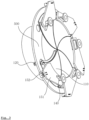
- the blocking device may further include a wire part 700 which is annular-shaped, and the wire part 700 is sleeved outside a channel portion as described below, and the wire part 700 is arranged on one side of the second receiving part 600 described below away from the first receiving part 500.
- the wire part 700 may further include multiple electrical connectors, and the number of the multiple electrical connectors is equal to the number of the blocking assemblies.
- the multiple electrical connectors are uniformly distributed in a circumferential direction of the wire part 700, to make the electrical connectors be in one-to-one correspondence with the projecting portions 152, and the projecting portion 152 may be electrically connected to the corresponding electrical connector via a wire to supply power for the projecting portion 152.
- the light-emitting assembly 800 can be turned on to allow the light beam from the light-emitting assembly 800 to directly irradiate the blocking assemblies 110, so as to realize a front-projecting state of the vehicle lamp as described below.
- the blocking device may further include a first receiving part 500, which includes a channel portion and an annulus portion being connected to each other.
- the channel portion includes a cylindrical channel, an axis of the cylindrical channel coincides with an axis of the blocking body, the annulus portion is arranged between the transmission part 200 and the multiple blocking assemblies, and the rotary shaft 120 runs through the annulus portion.
- the transmission part 200 and the rotary gears 130 are separated from the blocking sheets 110, effectively preventing the blocking sheet 110 from interfering with the transmission part 200 and the rotary gears 130 during rotation, and thereby ensuring the transmission stability of the blocking device.
- the light-emitting assembly 800 is arranged at one end of the cylindrical channel.
- the annulus portion is provided at the other end of the cylindrical channel, so that when the blocking assemblies are in the first state, the blocking body can block the cylindrical channel to realize blocking of the light-emitting assembly 800.
- the channel portion can effectively prevent the light emitted by the light-emitting assembly 800 from transmitting through a gap between the light-emitting assembly 800 and the blocking body, thus effectively improving the effect of the front-projecting illumination of the light-blocking sheet.
- the blocking device further includes a second receiving part 600 being in an annular shape, the second receiving part is sleeved outside the above channel portion.
- the second receiving part 600 is arranged on one side of the transmission part 200 away from the multiple blocking assemblies; one end of the rotary shaft 120 is connected to the second receiving part 600, and the other end of the rotary shaft 120 is connected to the blocking sheet.
- a transmission space is defined between the first receiving part and the second receiving part 600 by enclosing, so that the transmission part 200 and the rotary gears 130 can perform stable transmission in the transmission space, and the transmission part 200 and the rotary gears 130 can be effectively limited by the first receiving part and the second receiving part 600.
- the vehicle lamp includes the blocking device described in any one of the above embodiments, and thus the vehicle lamp has all the beneficial technical effects of the blocking device, which will not be described in detail here.
- the vehicle lamp further includes the above light-emitting assembly 800.
- the blocking assemblies When the blocking assemblies are in the first state, the vehicle lamp may be switched among a resting state, a side-projecting state and a front-projecting state. Specifically, when the vehicle lamp is in the resting state, both the light-emitting assembly 800 and the projecting parts are set not to emit light, so that the vehicle lamp can be adjusted to the resting state when the vehicle is shutdown.
- the light-emitting assembly 800 may be an LED, an xenon lamp, a halogen lamp, or the like.
Landscapes
- Engineering & Computer Science (AREA)
- General Engineering & Computer Science (AREA)
- Mechanical Engineering (AREA)
- Non-Portable Lighting Devices Or Systems Thereof (AREA)
Applications Claiming Priority (2)
| Application Number | Priority Date | Filing Date | Title |
|---|---|---|---|
| CN202210793956.6A CN115164168B (zh) | 2022-07-05 | 2022-07-05 | 遮挡装置及车灯 |
| PCT/CN2023/105804 WO2024008107A1 (fr) | 2022-07-05 | 2023-07-05 | Dispositif de blocage et lampe de véhicule |
Publications (2)
| Publication Number | Publication Date |
|---|---|
| EP4553379A1 true EP4553379A1 (fr) | 2025-05-14 |
| EP4553379A4 EP4553379A4 (fr) | 2026-03-25 |
Family
ID=83491731
Family Applications (1)
| Application Number | Title | Priority Date | Filing Date |
|---|---|---|---|
| EP23834874.2A Pending EP4553379A4 (fr) | 2022-07-05 | 2023-07-05 | Dispositif de blocage et lampe de véhicule |
Country Status (3)
| Country | Link |
|---|---|
| EP (1) | EP4553379A4 (fr) |
| CN (1) | CN115164168B (fr) |
| WO (1) | WO2024008107A1 (fr) |
Families Citing this family (2)
| Publication number | Priority date | Publication date | Assignee | Title |
|---|---|---|---|---|
| CN115164168B (zh) * | 2022-07-05 | 2024-05-03 | 曼德电子电器有限公司 | 遮挡装置及车灯 |
| CN115218159A (zh) * | 2022-07-05 | 2022-10-21 | 曼德电子电器有限公司 | 车辆远近光透镜隐藏机构及车辆灯具 |
Family Cites Families (20)
| Publication number | Priority date | Publication date | Assignee | Title |
|---|---|---|---|---|
| US1084113A (en) * | 1912-10-28 | 1914-01-13 | Gilbert G Rosino | Headlight-dimmer. |
| DE428123C (de) * | 1925-02-18 | 1926-04-24 | Karl Bauer | Scheinwerfer fuer Kraftfahrzeuge |
| BE351504A (fr) * | 1928-05-23 | 1928-06-30 | ||
| JPS482124A (fr) * | 1971-05-21 | 1973-01-12 | ||
| JPH0743786A (ja) * | 1993-07-30 | 1995-02-14 | Toshiba Lighting & Technol Corp | 絞り機構及び投光装置 |
| AT413752B (de) * | 2000-03-23 | 2006-05-15 | Zizala Lichtsysteme Gmbh | Fahrzeugscheinwerfer |
| US20060245184A1 (en) * | 2005-04-29 | 2006-11-02 | Galli Robert D | Iris diffuser for adjusting light beam properties |
| JP2007194166A (ja) * | 2006-01-23 | 2007-08-02 | Stanley Electric Co Ltd | 車両用灯具 |
| JP4953922B2 (ja) * | 2007-05-30 | 2012-06-13 | 株式会社小糸製作所 | 車両用前照灯 |
| US8113691B2 (en) * | 2008-03-11 | 2012-02-14 | Robe Lighting S.R.O. | Color change mechanism |
| CN106016172B (zh) * | 2016-07-08 | 2023-04-14 | 广州市珠江灯光科技有限公司 | 联动遮光系统、灯具及联动遮光控制方法 |
| DE102018005462A1 (de) * | 2018-07-10 | 2018-12-27 | Daimler Ag | Heckleuchtenmodul und Heckleuchte |
| CN111727346B (zh) * | 2019-01-23 | 2022-12-06 | 瑞仪光电(苏州)有限公司 | 灯具 |
| CN112849276B (zh) * | 2019-11-28 | 2022-04-19 | 长城汽车股份有限公司 | 盖体结构 |
| CN211572191U (zh) * | 2020-01-07 | 2020-09-25 | 天津多赢科技发展有限公司 | 一种装配式木结构建筑屋顶 |
| CN111717545A (zh) * | 2020-06-01 | 2020-09-29 | 重庆大学 | 瓶口可调式药瓶 |
| CN111853684A (zh) * | 2020-07-31 | 2020-10-30 | 广州市浩洋电子股份有限公司 | 一种可精准定位的光束切割装置及具有其的舞台灯 |
| CN214468096U (zh) * | 2021-03-09 | 2021-10-22 | 浙江金华市顺泰水电建设有限公司 | 一种建筑用便于调节照射范围的节电照明装置 |
| CN214468365U (zh) * | 2021-05-11 | 2021-10-22 | 长城汽车股份有限公司 | 车用雾灯总成和车辆 |
| CN115164168B (zh) * | 2022-07-05 | 2024-05-03 | 曼德电子电器有限公司 | 遮挡装置及车灯 |
-
2022
- 2022-07-05 CN CN202210793956.6A patent/CN115164168B/zh active Active
-
2023
- 2023-07-05 EP EP23834874.2A patent/EP4553379A4/fr active Pending
- 2023-07-05 WO PCT/CN2023/105804 patent/WO2024008107A1/fr not_active Ceased
Also Published As
| Publication number | Publication date |
|---|---|
| WO2024008107A1 (fr) | 2024-01-11 |
| EP4553379A4 (fr) | 2026-03-25 |
| CN115164168B (zh) | 2024-05-03 |
| CN115164168A (zh) | 2022-10-11 |
Similar Documents
| Publication | Publication Date | Title |
|---|---|---|
| EP4553379A1 (fr) | Dispositif de blocage et lampe de véhicule | |
| EP4553375A1 (fr) | Lentille de feux de route de véhicule et mécanisme de dissimulation de lentille de feux de croisement et lampe de véhicule | |
| JP2012015012A (ja) | Led照明装置 | |
| WO2023085227A1 (fr) | Actionneur et procédé d'assemblage d'actionneur | |
| RU2850717C2 (ru) | Блокирующее устройство и фара транспортного средства | |
| WO2023245983A1 (fr) | Lampe de focalisation | |
| CN223049891U (zh) | 一种防眩光结构及柔性灯带 | |
| CN106016172B (zh) | 联动遮光系统、灯具及联动遮光控制方法 | |
| CN220169365U (zh) | 一种触摸式可调光台灯 | |
| CN112672568A (zh) | 电子设备 | |
| JP2019110004A (ja) | 導光チューブの製造方法、及び導光チューブ | |
| CN116398857A (zh) | 一种可切换照射形态的打光装置 | |
| CN212719246U (zh) | 边缘发光的氛围灯 | |
| CN218209067U (zh) | 一种可自动调节的led灯泡 | |
| DE19902774A1 (de) | Leuchtkörper mit Leuchtdioden für Selbstleuchter und zur Hinterleuchtung von Hinweiselementen | |
| JP2008123852A (ja) | 照明装置 | |
| CN223649168U (zh) | 一种光斑宽度可调的条纹光源 | |
| CN223165460U (zh) | 一种可调线性光源装置及检测装置 | |
| JP7579769B2 (ja) | アクチュエータの組立方法 | |
| CN220082916U (zh) | 一种灯具 | |
| EP3173693B1 (fr) | Appareil d'éclairage comprenant une pluralité d'ampoules à del | |
| CN217423115U (zh) | 遮挡组件、车灯模组及汽车 | |
| CN221592739U (zh) | 办公灯无暗区发光连接灯 | |
| CN223649228U (zh) | 一种环形光源装置 | |
| CN219040011U (zh) | 一种可识别通道状态指引灯 |
Legal Events
| Date | Code | Title | Description |
|---|---|---|---|
| STAA | Information on the status of an ep patent application or granted ep patent |
Free format text: STATUS: THE INTERNATIONAL PUBLICATION HAS BEEN MADE |
|
| PUAI | Public reference made under article 153(3) epc to a published international application that has entered the european phase |
Free format text: ORIGINAL CODE: 0009012 |
|
| STAA | Information on the status of an ep patent application or granted ep patent |
Free format text: STATUS: REQUEST FOR EXAMINATION WAS MADE |
|
| 17P | Request for examination filed |
Effective date: 20250206 |
|
| AK | Designated contracting states |
Kind code of ref document: A1 Designated state(s): AL AT BE BG CH CY CZ DE DK EE ES FI FR GB GR HR HU IE IS IT LI LT LU LV MC ME MK MT NL NO PL PT RO RS SE SI SK SM TR |
|
| DAV | Request for validation of the european patent (deleted) | ||
| DAX | Request for extension of the european patent (deleted) | ||
| A4 | Supplementary search report drawn up and despatched |
Effective date: 20260219 |
|
| RIC1 | Information provided on ipc code assigned before grant |
Ipc: F21V 14/00 20180101AFI20260213BHEP Ipc: F21V 1/10 20060101ALI20260213BHEP Ipc: F21S 43/20 20180101ALI20260213BHEP Ipc: F16H 1/28 20060101ALI20260213BHEP Ipc: F21S 41/50 20180101ALI20260213BHEP Ipc: F21S 43/239 20180101ALI20260213BHEP Ipc: F21S 43/245 20180101ALI20260213BHEP Ipc: F21S 43/50 20180101ALI20260213BHEP Ipc: F21S 45/10 20180101ALI20260213BHEP Ipc: F21S 43/00 20180101ALI20260213BHEP Ipc: B60Q 1/14 20060101ALI20260213BHEP |