EP4553380A1 - Panneau lumineux portatif - Google Patents
Panneau lumineux portatif Download PDFInfo
- Publication number
- EP4553380A1 EP4553380A1 EP24212807.2A EP24212807A EP4553380A1 EP 4553380 A1 EP4553380 A1 EP 4553380A1 EP 24212807 A EP24212807 A EP 24212807A EP 4553380 A1 EP4553380 A1 EP 4553380A1
- Authority
- EP
- European Patent Office
- Prior art keywords
- housing
- panel
- portable light
- light
- electronic components
- Prior art date
- Legal status (The legal status is an assumption and is not a legal conclusion. Google has not performed a legal analysis and makes no representation as to the accuracy of the status listed.)
- Pending
Links
Images


Classifications
-
- F—MECHANICAL ENGINEERING; LIGHTING; HEATING; WEAPONS; BLASTING
- F21—LIGHTING
- F21V—FUNCTIONAL FEATURES OR DETAILS OF LIGHTING DEVICES OR SYSTEMS THEREOF; STRUCTURAL COMBINATIONS OF LIGHTING DEVICES WITH OTHER ARTICLES, NOT OTHERWISE PROVIDED FOR
- F21V29/00—Protecting lighting devices from thermal damage; Cooling or heating arrangements specially adapted for lighting devices or systems
- F21V29/50—Cooling arrangements
- F21V29/502—Cooling arrangements characterised by the adaptation for cooling of specific components
- F21V29/508—Cooling arrangements characterised by the adaptation for cooling of specific components of electrical circuits
-
- F—MECHANICAL ENGINEERING; LIGHTING; HEATING; WEAPONS; BLASTING
- F21—LIGHTING
- F21V—FUNCTIONAL FEATURES OR DETAILS OF LIGHTING DEVICES OR SYSTEMS THEREOF; STRUCTURAL COMBINATIONS OF LIGHTING DEVICES WITH OTHER ARTICLES, NOT OTHERWISE PROVIDED FOR
- F21V15/00—Protecting lighting devices from damage
- F21V15/01—Housings, e.g. material or assembling of housing parts
-
- F—MECHANICAL ENGINEERING; LIGHTING; HEATING; WEAPONS; BLASTING
- F21—LIGHTING
- F21V—FUNCTIONAL FEATURES OR DETAILS OF LIGHTING DEVICES OR SYSTEMS THEREOF; STRUCTURAL COMBINATIONS OF LIGHTING DEVICES WITH OTHER ARTICLES, NOT OTHERWISE PROVIDED FOR
- F21V29/00—Protecting lighting devices from thermal damage; Cooling or heating arrangements specially adapted for lighting devices or systems
- F21V29/50—Cooling arrangements
- F21V29/60—Cooling arrangements characterised by the use of a forced flow of gas, e.g. air
- F21V29/67—Cooling arrangements characterised by the use of a forced flow of gas, e.g. air characterised by the arrangement of fans
- F21V29/673—Cooling arrangements characterised by the use of a forced flow of gas, e.g. air characterised by the arrangement of fans the fans being used for intake
-
- F—MECHANICAL ENGINEERING; LIGHTING; HEATING; WEAPONS; BLASTING
- F21—LIGHTING
- F21V—FUNCTIONAL FEATURES OR DETAILS OF LIGHTING DEVICES OR SYSTEMS THEREOF; STRUCTURAL COMBINATIONS OF LIGHTING DEVICES WITH OTHER ARTICLES, NOT OTHERWISE PROVIDED FOR
- F21V29/00—Protecting lighting devices from thermal damage; Cooling or heating arrangements specially adapted for lighting devices or systems
- F21V29/50—Cooling arrangements
- F21V29/70—Cooling arrangements characterised by passive heat-dissipating elements, e.g. heat-sinks
- F21V29/74—Cooling arrangements characterised by passive heat-dissipating elements, e.g. heat-sinks with fins or blades
-
- F—MECHANICAL ENGINEERING; LIGHTING; HEATING; WEAPONS; BLASTING
- F21—LIGHTING
- F21V—FUNCTIONAL FEATURES OR DETAILS OF LIGHTING DEVICES OR SYSTEMS THEREOF; STRUCTURAL COMBINATIONS OF LIGHTING DEVICES WITH OTHER ARTICLES, NOT OTHERWISE PROVIDED FOR
- F21V29/00—Protecting lighting devices from thermal damage; Cooling or heating arrangements specially adapted for lighting devices or systems
- F21V29/50—Cooling arrangements
- F21V29/70—Cooling arrangements characterised by passive heat-dissipating elements, e.g. heat-sinks
- F21V29/83—Cooling arrangements characterised by passive heat-dissipating elements, e.g. heat-sinks the elements having apertures, ducts or channels, e.g. heat radiation holes
-
- F—MECHANICAL ENGINEERING; LIGHTING; HEATING; WEAPONS; BLASTING
- F21—LIGHTING
- F21W—INDEXING SCHEME ASSOCIATED WITH SUBCLASSES F21K, F21L, F21S and F21V, RELATING TO USES OR APPLICATIONS OF LIGHTING DEVICES OR SYSTEMS
- F21W2131/00—Use or application of lighting devices or systems not provided for in codes F21W2102/00-F21W2121/00
- F21W2131/40—Lighting for industrial, commercial, recreational or military use
- F21W2131/406—Lighting for industrial, commercial, recreational or military use for theatres, stages or film studios
-
- F—MECHANICAL ENGINEERING; LIGHTING; HEATING; WEAPONS; BLASTING
- F21—LIGHTING
- F21Y—INDEXING SCHEME ASSOCIATED WITH SUBCLASSES F21K, F21L, F21S and F21V, RELATING TO THE FORM OR THE KIND OF THE LIGHT SOURCES OR OF THE COLOUR OF THE LIGHT EMITTED
- F21Y2105/00—Planar light sources
- F21Y2105/10—Planar light sources comprising a two-dimensional [2D] array of point-like light-generating elements
- F21Y2105/14—Planar light sources comprising a two-dimensional [2D] array of point-like light-generating elements characterised by the overall shape of the two-dimensional [2D] array
-
- F—MECHANICAL ENGINEERING; LIGHTING; HEATING; WEAPONS; BLASTING
- F21—LIGHTING
- F21Y—INDEXING SCHEME ASSOCIATED WITH SUBCLASSES F21K, F21L, F21S and F21V, RELATING TO THE FORM OR THE KIND OF THE LIGHT SOURCES OR OF THE COLOUR OF THE LIGHT EMITTED
- F21Y2115/00—Light-generating elements of semiconductor light sources
- F21Y2115/10—Light-emitting diodes [LED]
-
- G—PHYSICS
- G03—PHOTOGRAPHY; CINEMATOGRAPHY; ANALOGOUS TECHNIQUES USING WAVES OTHER THAN OPTICAL WAVES; ELECTROGRAPHY; HOLOGRAPHY
- G03B—APPARATUS OR ARRANGEMENTS FOR TAKING PHOTOGRAPHS OR FOR PROJECTING OR VIEWING THEM; APPARATUS OR ARRANGEMENTS EMPLOYING ANALOGOUS TECHNIQUES USING WAVES OTHER THAN OPTICAL WAVES; ACCESSORIES THEREFOR
- G03B2215/00—Special procedures for taking photographs; Apparatus therefor
- G03B2215/05—Combinations of cameras with electronic flash units
- G03B2215/0514—Separate unit
- G03B2215/0517—Housing
Definitions
- the field of disclosure relates generally to a portable light panel and, more particularly, to a portable light panel with direct cooling of electronic components that control the light emitted from the light panel.
- Portable light panels may be used to provide suitable lighting outside of a studio.
- the portable light panels may also be used singly or in combination with in-studio light fixtures.
- portable light panels When outside of the studio, portable light panels may be used to provide lighting during remote reporting at sporting or non-sporting events, or when filming a movie or show for television, for example.
- the portable light panels are typically supported by an adjustable stand or frame that enables the vertical position of the attached light to be modified for use at the associated sporting or non-sporting event.
- the portable lights include a plurality of light emitting components such as a plurality of light emitting diodes (LED's).
- the LED's are controlled by circuit board and other electronics (collectively “electrical components") that are located in a portable light housing.
- electrical components produce heat that causes their temperature to increase.
- the electrical components need to be actively cooled to prevent the operating temperature of the electrical components from rising to a level that would lead to heat-related damage to the components.
- typical portable lights draws cool ambient air into the light housing from the rear of the housing.
- the air must travel through the housing until it reaches the electrical components. Because the air must travel through the housing, the air passes a number of housing structural components and other components that have an operating temperature that is likely greater than the temperature of the ambient air. As a result, the temperature of the ambient air increases as it moves through the housing toward the electrical components to be cooled. The temperature of the ambient air is lower when the air is drawn into the housing than the temperature of the ambient air when it is flowed against the electrical components.
- the ambient air cools the electrical components less effectively than if the drawn in air was directly flowed against the electrical components.
- the components would be more effectively cooled if the cool ambient air was drawn into the housing and then directly flowed against the electrical components.
- the present disclosure describes a portable light that draws ambient air through at least one inlet along the periphery of the portable light, through a flow chamber and against the electrical components of the portable light.
- inventive concept is set out in claims 1, 7 and 15. Further optional features are set out in the dependent claims.
- a portable light panel comprising:
- the present disclosure also provides a portable light panel comprising:
- the present disclosure further provides a portable light panel comprising:
- a portable light panel comprising: a housing having a rear portion, a front portion and peripheral portions between the front and rear portions, the peripheral portions including air intake openings, the housing defining an air intake chamber; a light emitting panel; electronic components to control the light emitted by the light-emitting panel, the electronic components being located proximate the air intake chamber between the housing and the light emitting panel, and wherein the ambient air is drawn into the air intake chamber and directed onto the electronic components to maintain the electronic components at a desired operating temperature.
- portable light or “portable light panel”, or “light” refers to any portable light structure.
- electrical components refers collectively to circuit boards, electric devices, electronics and other electrically powered components.
- the term "about” refers to a measurable value such as a parameter, an amount, a temporal duration, and the like and is meant to include variations of +/- 15% or less, preferably variations of +/- 10% or less, more preferably variations of +/- 5% or less, even more preferably variations of +/- 1% or less, and still more preferably variations of +/- 0.1% or less of and from the particularly recited value, in so far as such variations are appropriate to perform in the invention described herein. Furthermore, it is also to be understood that the value to which the modifier "about” refers is itself specifically disclosed herein.
- spatially relative terms such as “beneath”, “below”, “lower”, “above”, “upper”, “front”, “back”, “side”, “left”, “right”, “rear”, “top”, “bottom”, and the like, are used for ease of description to describe one element or feature's relationship to another element(s) or feature(s). It is further understood that the terms “front”, “back”, “left”, and “right” are not intended to be limiting and are intended to be interchangeable, where appropriate. Further, it should be noted that the terms “first,” “second,” and the like herein do not denote any order, quantity, or relative importance, but rather are used to distinguish one element from another.
- configure(s) refer to the capability of a component and/or assembly, but do not preclude the presence or addition of other capabilities, features, components, elements, operations, and any combinations thereof.
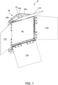
- Portable light panel 10 is shown in Figure 1 .
- the portable light panel 10 includes inlet openings along the periphery of the portable light panel that enable ambient air to flow into a housing flow channel and then against electric components that control the light emitted by the portable light.
- the relatively cool ambient air effectively maintains the operating temperature of the components below a temperature that would likely cause damage to the electric components.
- the portable light panel 10 comprises a housing 20, electrical components 30 and light emitting panel 40 located adjacent electrical components 30.
- the electrical components 30, control the attributes of the light emitted from the light emitting panel 40.
- the light emitting panel 40 and electrical components 30 are located adjacent the front portion of the housing 20.
- the portable light 10 has a rectangular peripheral configuration.
- each portion of the periphery of the housing may include a movable door 11A, 11B, 11C and 11D.
- the doors have a rectangular shape that is similar to the shape of the light emitting panel.
- the doors are provided to selectably direct the light emitted from the light emitting panel 40 to an object that is to receive the emitted light.
- Each of the doors 11A, 11B, 11C, and 11D is hingeably connected to the housing 20 to be movable toward and away from the light emitting panel 40.
- the door may be located in a closed orientation where the door is in a plane that is parallel to the plane defined by the light-emitting panel 40 or in an orientation that forms an obtuse angle with the light emitting panel 40.
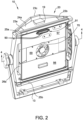
- the portable light panel 10 is shown in Figure 2 with the light emitting panel 40 removed from the housing.
- the housing 20 has a v-shaped lateral configuration.
- the housing includes a back panel, shown in Figure 3 , end panels 24a, 24b shown in Figures 2 and 7 respectively, and side peripheral portions 26a, 26b extending between the end panels.
- the side peripheral portions are shown in Figure 3 and Figure 4 .
- U-shaped handles 28a, 28b are included along each side of the housing 20. Each handle has a pair of ends 29a, 29b. The ends 29a, 29b of the respective handles 28a, 28b are connected to the side peripheral portions 26a, 26b by conventional fasteners such as screws or bolts.
- the handles When the handles are connected to the housing 20, in combination the housing and respective handles form openings 27a and 27b.
- Handle 28a and peripheral portion 26a form opening 27a.
- Peripheral portion 26b and handle 28b form opening 27b.
- an operator of the portable light 10 can support the light by gripping the light at the openings 27a, 27b. The operator can walk and hold the light using the handles.
- each end of the housing wall includes central surface 23c, and tapered surfaces 23a, 23b.
- the central surfaces 23c are located the greatest longitudinal distance from respective end panels 24a, 24b.
- the tapered surfaces 23a, and 23b extend from the central surface 23c, and extend at an angle toward peripheral portions 26a, 26b respectively.
- Laterally extending rib members 25a, 25b extend between the peripheral portions 26a, 26b. Rib 25a is located proximate end panel 24a, and rib 25b is located proximate end panel 24b.
- the top surface 31a, 31b of each rib 25a, 25b respectively is located longitudinally inward from center surface 23c.
- the portable light panel may be placed on a surface 100 by locating the central surface 23c and rib surface 31b in contact with the surface 100.
- a u-shaped yoke 13 may be removably connected to the handles 28a, 28b by conventional fasteners. The yoke 13 may be in turn connected to a stand or rotated away from bottom end panel 24b when the portable light is supported on a surface as shown in Figure 7 .
- a trapezoidal shaped hub 19 may be disposed on end panel 24a, as shown in Figures 1 and 2 .
- a display interface 36 such as an LCD is provided along the rear wall 22.
- the display interface may provide menus selectable by the light operator to adjust the attributes of the light emitted by the portable light 10.
- Rotation of knob 35 enables the user to move through menus displayed on the display interface 36.
- the knob 35 may be pressed to select a desired light operation option.
- Separate control knobs 32 and 34 are used to respectively control the dimming level or color temperature of the light panel 40. Rotation of knob 32 enables the user to adjust the brightness of the emitted light from 0-100% and rotation of knob 34 enables the user to adjust the color temperature of the LED's to cause the color of the emitted light to range from tungsten to daylight.
- a removable cap 38 covers a communication module.
- the communication module may enable Wi-Fi control of the light 10 and also include outlets, ports or other connectors when not in use.
- the outlets may comprise known usb-c or power outlets for example.
- the removable cap 38 has a trapezoidal shape similar to the trapezoidal shape of hub 19. When the cap 38 is removed, the cap 38 may be seated and stored on hub 19. As a result, the cap 38 may be effectively and efficiently relocated on the outlets when they are no longer in use.
- the cap sealingly engages the housing 15 that is supporting and enclosing the components that comprise the communication module.
- the free ends of the cap 38 include flanges 101a, 101b that overlay the free ends of the wall of the communication module housing 15. As a result the components of the communication module are protected from water or other particulate matter.
- the bottom end panel 24b includes a power switch 42 for selectively providing power to the portable light 10.
- a first connector 43 that may be a three-pin XLR connector for use connecting a battery to the portable light to provide 10-30 V of DC current to the portable light 10.
- a second connector 44 that may comprise a connector for providing AC current 90-260 V and 50-60Hz to the portable light 10. The connectors are disclosed for exemplary purposes and may comprise any required connector for supplying power to the portable light.
- the light emitting panel comprises a plurality of light-emitting components 41 such as a plurality of light emitting diodes (LED's). See Figure 4 .
- the LED's are controlled by circuit board and other electronics (collectively “electrical components") 30 that are located immediately adjacent the components 41.
- the plurality of light emitting components are spaced along the entirety of the light emitting panel 40 in a portable light housing.
- the electrical components 30 produce heat that causes their temperature to increase.
- the electrical components 30 need to be actively cooled to prevent the operating temperature of the electrical components 30 from rising to a level that would lead to heat-related damage to the electrical components 30.
- the housing 20 includes a v-shaped panel 60 that is oriented substantially parallel to the rear wall 22.
- the panel 60 comprises center panel 61c, and side panels 61a and 61b that extend from the center portion and are made integral with respective peripheral portions 26a, 26b.
- An interior housing wall 63 is located adjacent panel 60 and is oriented perpendicular to the panel 60. The interior housing wall 63 impedes the flow of inlet ambient air toward the end panel 26b as it is drawn into the housing.
- a frame 69 supports a fan 70. The frame may be connected to the wall 63 in a conventional manner. As supported by the frame, the fan 70 is located proximate the center panel 61c of the panel 60.
- the fan 70 and center panel 61c are separated by a distance that permits air to flow therebetween.
- Electrical components 30 are located proximate the fan 70. A distance separates the fan and electrical components to enable air to flow therebetween.
- the panel 60, wall 63 and frame 69 define an air intake chamber 73.
- Ambient air inlets 71a, 71b are provided along respective peripheral portions 26a and 26b. Ambient air enters the intake chamber 73 through the inlets in the direction of arrows 74a, 74b. In operation, the rotating fan draws ambient air into the intake chamber 73 through inlets 71a, 71b. The air is drawn toward the fan, passes through the fan and is exhausted from the fan and directly against the electrical components 30 to maintain the temperature of the electrical components at an acceptable operating temperature. The air is exhausted from the fan in direction 75.
- the portable light includes electronics (not shown) located proximate rear housing wall 22 and the electronics 30 that are located adjacent the front of the housing 20.
- a number of discrete members for making electrical connections between the electronics may be used.
- the members, such as wires are passed through a number of the discrete openings 90 that are provided in membrane 91.
- the membrane 91 includes a plurality of aligned, spaced apart openings 90.
- the membrane may be provided on a housing structural member located between the front and rear portions of the housing. In use, a pressure difference may exist between the rear portion of the portable light and the front portion of the portable light proximate the electronics 30, light emitting panel 40 and air intake chamber.
- a number of the openings 90 in membrane 91 do not include connectors and remain open, thereby permitting air to pass from the housing portion of relative high pressure to the portion of the housing of relative low pressure to balance the pressure, eliminating any stress on portable light component parts such as seals for example.
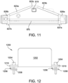
- FIGS 8-15 disclose an alternate embodiment portable light 810 of the present disclosure.
- the alternate embodiment portable light 810 includes the electronics 30, control knobs 32, 34, 35, Wifi cap 38, membrane 91, and components associated therewith and previously described. As a result no further description of these components and features will be made relative to the portable light panel 810.
- the light panels 10, 810 are shown with an aspect ratio of width to height of 1:1.
- the portable light panel 810 includes a housing 820 with top portion 831a, bottom portion 831b, first side portion 826a, second side portion 826b, and rear portion 822.
- the rear portion 822, and first and second side portions 826a, 826b extend between the top and bottom portions 831a and 831b.
- a light emitting panel 840 is supported by the housing 820 along the front of the housing opposite the rear portion 822.
- the rear portion 822 terminates at the bottom portion 831b at central surface 823c, and tapered surfaces 823a and 823b.
- the central surface 823c and tapered surfaces 823b and 823a are configured in the manner previously described relative to respective central and tapered surfaces 23c, 23a and 23b of portable light panel 10.
- Handles 828a, and 828b are formed along the respective side portions 826a, 826b.
- the handles may be gripped by an operator when the position or orientation of the portable light 810 needs to be adjusted or when the light needs to be relocated to a new location.
- Handles 828a and 828b may include upper ambient air inlets 872a, 872b are provided along respective handles 826a and 826b. Ambient air may enter housing 820 through upper ambient air inlets 872a, 872b.
- the bottom portion may_include a hub 819.
- the hub has a rectangular shape.
- the hub 819 is located proximate rear portion 822.
- the light panel may be fully seated on the hub 819, central surfaces 823c, as well as the bottom surfaces 837a and 837b of the respective side portions 826a and 826b.
- the surfaces 823c, 837a, and 837b are shown seated on base 1000 represented in dashed font in Figure 8 .
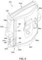
- the rear portion 822 includes a groove 900 that extends along the rear portion 822 between the top portion 831a and the bottom portion 831b. As shown in Figure 9 and Figure 10 , the groove 900 is located proximate side portion 826b. It should be understood that the groove may be located in any suitable location along the rear portion 822.
- the groove 900 overlays a recessed portion 906 in the housing 820. The recessed portion extends the full length of the groove.
- the groove 900 includes a narrow portion 902.
- a groove wide portion 904 is located along groove narrow portion 902 near the end of the groove 900 near housing bottom portion 831b.
- the groove wide portion 904 has a lateral dimension that is greater than the lateral dimension of the groove narrow portion 902.
- the groove wide portion may be located at any suitable location along the length of the groove 900.
- the groove 900 includes groove edge 912. The wide portion of the groove is suitably wide to receive a fastener as described further below.
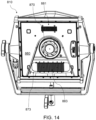
- Figure 12 schematically represents an accessory 1200 for the portable light 810.
- the accessory 1200 may be comprise a battery.
- the accessories may be conveniently stored along the rear portion 822 of the housing by securing the accessory to the groove.
- the accessory 1200 may comprise a cover 1202 with a sealing member (not shown) to ensure that the accessory is protected from liquid when the accessory is located along the rear portion.
- the cover 1202 includes a pair of flanges 1210 that support fasteners 1204 which may comprise any suitable fastener such as an allen nut for example.
- a washer 1206 may be included along the length of each fastener 1204, and separated from the underside of each flange by a gap 1206.
- the groove edge 912 is located in the gap 1206 when the accessory 1200 is positioned along the groove.
- one of the washers 1208 is located in the wide groove portion 904 and the groove edge 912 is located in the gap between the washer and underside of the associated flange 1210.
- the accessory is then slid along the groove narrow portion toward top portion 831a.
- the groove edge 912 is located in the gap 1206 between the associate washer 1208 and the underside of the associated flange 1210.
- the accessory continues along groove 900 toward top portion 831a until the accessory is in the desired location.
- the fasteners 1204 can then be tightened to secure the accessory in place.
- the accessory 1200 is presented in dashed font in Fig. 10 . If the accessory is a battery, when the battery powering the portable light needs to be replaced, the fasteners may be loosened to removed the accessory from the groove and used to replace the battery without losing power to the portable light.
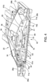
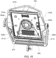
- the portable light panel 810 is shown in Figures 13-15 with the light emitting panel removed from the housing.
- Portable light panel 810 may include a housing panel 860 that provides support for a fan 870.
- the housing panel 860 may be connected to the housing 820 in a conventional manner and a define a front electronic housing and a back electronic housing.
- the fan 870 is located proximate a center of panel 860, in a U-shaped opening formed in panel 860.
- panel 860 may include a cover plate 877 attached to panel 860 in a conventional manner.
- Panel 860, U-shaped opening, and cover plate 877 in combination define an air chamber 873 that permits air to flow therebetween into and/or from fan 870.
- Electrical components 30 are located proximate the fan 870. A distance separates the fan 870 and electrical components 30 to enable air to flow therebetween to and/or from fan 870.
- portable light 810 may include electronics (not shown) located within back electronic housing that are proximate rear housing wall 822 and the electronics 30 that are located within front electronic housing that may require ambient air flow to maintains the operating temperature of these components.
- Panel 860 may direct a portion of ambient air that enters housing 820 through lower air inlets 871a, 871b and upper air inlets 872a, 872b through a first heat sink 881 and a second heat sink 883 for electronic components located within back electronic housing for cooling of these electronic components.
- First heat sink 881 is positioned on a portion of housing panel 860 to allow fluidic communication with ambient air flow within portable light panel 810.
- Second heat sink 883 is disposed within intake chamber 873 to allow for fluidic communication with ambient airflow within intake chamber 873.
- Fan 870 may be operated in a first direction to actively draw ambient air through lower air inlets 871a, 871b and upper air inlets 872a, 872b, pass the ambient air over the electrical components 30 to maintain the temperature of the electrical components 30 at an acceptable operating temperature, and panel 860 may direct the ambient air into fan 870. While operating fan 870 in the first direction, ambient air is drawn toward through the fan 870 and exhausted into air chamber 873, passes through second heat sink 883, and exits the air chamber 873 through apertures 879a and 879b.
- fan 870 may be operated in a second direction to actively draw ambient air through lower air inlets 871a, 871b and upper air inlets 872a, 872b and panel 860 may direct a portion of ambient air into the air chamber 873 through apertures 879a and 879b. While operating fan 870 in the second direction, ambient air is drawn toward the fan 870 though air chamber 873, passes through second heat sink 883, passes through the fan 870 and is exhausted from the fan 870 and directly against the electrical components 30 to maintain the temperature of the electrical components 30 at an acceptable operating temperature.
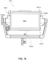
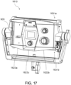
- FIGS 16-19 disclose an alternate embodiment portable light 1610 of the present disclosure.
- the alternate embodiment portable light 1610 includes the electronics 30, control knobs 32, 34, 35, membrane 91, groove 900 and components associated therewith and previously described. As a result no further description of these components and features will be made relative to the portable light panel 1610.
- the light panel 1610 is shown with an aspect ratio of width to height of 1:2.
- the portable light panel 1610 includes a housing 1620 with top portion 1631a, bottom portion 1631b, first side portion 1626a, second side portion 1626b, and rear portion 1622.
- the rear portion 1622, and first and second side portions 1626a, 1626b extend between the top and bottom portions 1631a and 1631b.
- a light emitting panel 1640 is supported by the housing 1620 along the front of the housing opposite the rear portion 1622.
- the rear portion 1622 terminates at the bottom portion 1631b at central surface 1623c, and tapered surfaces 1623a and 1623b.
- the central surface 1623c and tapered surfaces 1623b and 1623a are configured in a manner similar to previously described relative to respective central and tapered surfaces 23c, 23a and 23b of portable light panel 10.
- Bottom portion 1631b includes an ambient air slot 1675 extending along a width of bottom portion 1631b. Ambient air may additionally enter and exit housing 1620 through ambient air slot 1675.
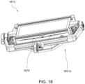
- the portable light panel 1610 is shown in Figure 19 with the light emitting panel removed from the housing.
- Portable light panel 1610 includes a housing panel 1660 connected to the housing 1620 in a conventional manner.
- Housing panel 1660 defines a front electronic housing and a back electronic housing.
- Housing panel 1660 and light emitting panel 1640 define an intake chamber 1673 that permits air to flow therebetween.
- portable light 1610 may include electronics (not shown) located within back electronic housing that are proximate rear housing wall 1622 and electronics 30 that are located within front electronic housing that may require ambient air flow to maintain the operating temperature of these components.
- Panel 1660 includes ridges 1665 to promote flow of ambient air that enters housing 1620 through ambient air slot 1675. Additionally, ambient air flow may be directed through a heat sink 1681 to dissipate heat from electronics located within back electronic housing. Heat sink 1681 may be positioned on a portion of panel 1660 to allow fluidic communication with ambient air flow within portable light panel 810. As air is drawn in through ambient air slot 1675, ambient air may flow directly against the electrical components 30 to maintain the temperature of the electrical components 30 at an acceptable operating temperature.
Landscapes
- Engineering & Computer Science (AREA)
- General Engineering & Computer Science (AREA)
- Arrangement Of Elements, Cooling, Sealing, Or The Like Of Lighting Devices (AREA)
Applications Claiming Priority (2)
| Application Number | Priority Date | Filing Date | Title |
|---|---|---|---|
| US202363598436P | 2023-11-13 | 2023-11-13 | |
| US202463572835P | 2024-04-01 | 2024-04-01 |
Publications (1)
| Publication Number | Publication Date |
|---|---|
| EP4553380A1 true EP4553380A1 (fr) | 2025-05-14 |
Family
ID=93521558
Family Applications (1)
| Application Number | Title | Priority Date | Filing Date |
|---|---|---|---|
| EP24212807.2A Pending EP4553380A1 (fr) | 2023-11-13 | 2024-11-13 | Panneau lumineux portatif |
Country Status (2)
| Country | Link |
|---|---|
| US (1) | US20250155115A1 (fr) |
| EP (1) | EP4553380A1 (fr) |
Families Citing this family (1)
| Publication number | Priority date | Publication date | Assignee | Title |
|---|---|---|---|---|
| USD1103455S1 (en) * | 2023-11-13 | 2025-11-25 | Videndum Production Solutions Inc. | Light panel |
Citations (4)
| Publication number | Priority date | Publication date | Assignee | Title |
|---|---|---|---|---|
| US20100128473A1 (en) * | 2008-11-21 | 2010-05-27 | Roland Parra | Adjustable LED Light Fixture |
| CN108343937A (zh) * | 2018-03-07 | 2018-07-31 | 广州市浩洋电子股份有限公司 | 一种舞台灯驱动板散热模组及舞台灯底机箱 |
| CN212160329U (zh) * | 2020-06-30 | 2020-12-15 | 广州斯芭克舞台设备有限公司 | 一种大功率投影灯 |
| US20230075501A1 (en) * | 2020-04-24 | 2023-03-09 | Aputure Imaging Industries Co., Ltd. | Heat dissipation device and lighting device |
Family Cites Families (13)
| Publication number | Priority date | Publication date | Assignee | Title |
|---|---|---|---|---|
| US6688759B1 (en) * | 2002-05-15 | 2004-02-10 | Andrew Hadjimichael | Plant growth-enhancing lamp device |
| US7686469B2 (en) * | 2006-09-30 | 2010-03-30 | Ruud Lighting, Inc. | LED lighting fixture |
| US20090129092A1 (en) * | 2007-11-21 | 2009-05-21 | Shyh-Ming Chen | Heat convection dissipater for led lamp |
| US8297782B2 (en) * | 2008-07-24 | 2012-10-30 | Bafetti Vincent H | Lighting system for growing plants |
| CN101929627A (zh) * | 2009-06-26 | 2010-12-29 | 富士迈半导体精密工业(上海)有限公司 | 照明装置 |
| JP2011187264A (ja) * | 2010-03-08 | 2011-09-22 | Rohm Co Ltd | 照明装置 |
| US20120020071A1 (en) * | 2010-07-22 | 2012-01-26 | Cammie Mckenzie | High performance led grow light |
| US9839206B2 (en) * | 2011-06-22 | 2017-12-12 | Ecotech Marine, Llc | Lighting unit and method of controlling |
| CN103827581A (zh) * | 2011-09-26 | 2014-05-28 | 普司科Led股份有限公司 | 光学半导体式发光装置 |
| US9404648B2 (en) * | 2014-01-15 | 2016-08-02 | Chilled Tech, Llc | LED light with cooling system |
| CA2916070C (fr) * | 2014-12-19 | 2021-10-26 | Nextlight, LLC | Lampe de serre a del |
| US10871275B2 (en) * | 2018-05-08 | 2020-12-22 | Nicor, Inc. | Lighting system family with modular parts and standardized extruded elements |
| CN108895379A (zh) * | 2018-07-19 | 2018-11-27 | 刘肖俊 | 一种高环保度节能led照明灯 |
-
2024
- 2024-11-13 EP EP24212807.2A patent/EP4553380A1/fr active Pending
- 2024-11-13 US US18/946,361 patent/US20250155115A1/en active Pending
Patent Citations (4)
| Publication number | Priority date | Publication date | Assignee | Title |
|---|---|---|---|---|
| US20100128473A1 (en) * | 2008-11-21 | 2010-05-27 | Roland Parra | Adjustable LED Light Fixture |
| CN108343937A (zh) * | 2018-03-07 | 2018-07-31 | 广州市浩洋电子股份有限公司 | 一种舞台灯驱动板散热模组及舞台灯底机箱 |
| US20230075501A1 (en) * | 2020-04-24 | 2023-03-09 | Aputure Imaging Industries Co., Ltd. | Heat dissipation device and lighting device |
| CN212160329U (zh) * | 2020-06-30 | 2020-12-15 | 广州斯芭克舞台设备有限公司 | 一种大功率投影灯 |
Also Published As
| Publication number | Publication date |
|---|---|
| US20250155115A1 (en) | 2025-05-15 |
Similar Documents
| Publication | Publication Date | Title |
|---|---|---|
| US11199315B2 (en) | Area luminaire | |
| EP2444717B1 (fr) | Lampe articulée à réglage automatiquement | |
| CN112309274A (zh) | 显示设备 | |
| EP4553380A1 (fr) | Panneau lumineux portatif | |
| AU2015266899B2 (en) | Area luminaire with heat fins | |
| US20160305617A1 (en) | Led lighting fixture with heat sink casing | |
| US7148452B2 (en) | Heat sink for printed circuit board components | |
| KR20100133460A (ko) | 일체형 조명 시스템을 구비한 전자 디스플레이 장치 | |
| US6660984B1 (en) | Wall-mounted type microwave oven | |
| CN106488605A (zh) | 光输出控制装置、照明系统和设施设备 | |
| US9719670B1 (en) | Fan cooled LED light and housing | |
| JP5214256B2 (ja) | 空間構造体 | |
| US20050254211A1 (en) | Heat dissipation module for electronic device | |
| EP2091300B1 (fr) | Dispositif de cuisson | |
| EP3324715B1 (fr) | Agencement de refroidissement pour un module d'alimentation électrique | |
| JP2008197392A (ja) | 薄型表示装置 | |
| CN1191954A (zh) | 微波炉 | |
| KR20030047156A (ko) | 벽걸이형 전자렌지 | |
| US20050254212A1 (en) | Heat dissipation module for electronic device | |
| JP2002344183A (ja) | 制御盤 | |
| JP7133783B2 (ja) | 照明器具 | |
| CN216010577U (zh) | 一种利用电控调光玻璃调节灯光效果的舞台灯 | |
| CN217273817U (zh) | 一种灯具 | |
| CN220701011U (zh) | 氛围拾音灯、中控屏总成及车辆 | |
| JP2001216823A (ja) | 光源装置及びスポット光源装置 |
Legal Events
| Date | Code | Title | Description |
|---|---|---|---|
| PUAI | Public reference made under article 153(3) epc to a published international application that has entered the european phase |
Free format text: ORIGINAL CODE: 0009012 |
|
| STAA | Information on the status of an ep patent application or granted ep patent |
Free format text: STATUS: THE APPLICATION HAS BEEN PUBLISHED |
|
| AK | Designated contracting states |
Kind code of ref document: A1 Designated state(s): AL AT BE BG CH CY CZ DE DK EE ES FI FR GB GR HR HU IE IS IT LI LT LU LV MC ME MK MT NL NO PL PT RO RS SE SI SK SM TR |
|
| STAA | Information on the status of an ep patent application or granted ep patent |
Free format text: STATUS: THE APPLICATION IS DEEMED TO BE WITHDRAWN |