EP4553435A1 - Configuration d'ailettes à onde sinusoïdale en forme de lance pour échangeurs de chaleur - Google Patents
Configuration d'ailettes à onde sinusoïdale en forme de lance pour échangeurs de chaleur Download PDFInfo
- Publication number
- EP4553435A1 EP4553435A1 EP24211928.7A EP24211928A EP4553435A1 EP 4553435 A1 EP4553435 A1 EP 4553435A1 EP 24211928 A EP24211928 A EP 24211928A EP 4553435 A1 EP4553435 A1 EP 4553435A1
- Authority
- EP
- European Patent Office
- Prior art keywords
- lance
- elements
- heat exchanger
- waves
- wave size
- Prior art date
- Legal status (The legal status is an assumption and is not a legal conclusion. Google has not performed a legal analysis and makes no representation as to the accuracy of the status listed.)
- Granted
Links
Images


Classifications
-
- F—MECHANICAL ENGINEERING; LIGHTING; HEATING; WEAPONS; BLASTING
- F28—HEAT EXCHANGE IN GENERAL
- F28F—DETAILS OF HEAT-EXCHANGE AND HEAT-TRANSFER APPARATUS, OF GENERAL APPLICATION
- F28F1/00—Tubular elements; Assemblies of tubular elements
- F28F1/10—Tubular elements and assemblies thereof with means for increasing heat-transfer area, e.g. with fins, with projections, with recesses
- F28F1/12—Tubular elements and assemblies thereof with means for increasing heat-transfer area, e.g. with fins, with projections, with recesses the means being only outside the tubular element
- F28F1/24—Tubular elements and assemblies thereof with means for increasing heat-transfer area, e.g. with fins, with projections, with recesses the means being only outside the tubular element and extending transversely
- F28F1/32—Tubular elements and assemblies thereof with means for increasing heat-transfer area, e.g. with fins, with projections, with recesses the means being only outside the tubular element and extending transversely the means having portions engaging further tubular elements
- F28F1/325—Fins with openings
-
- F—MECHANICAL ENGINEERING; LIGHTING; HEATING; WEAPONS; BLASTING
- F28—HEAT EXCHANGE IN GENERAL
- F28F—DETAILS OF HEAT-EXCHANGE AND HEAT-TRANSFER APPARATUS, OF GENERAL APPLICATION
- F28F1/00—Tubular elements; Assemblies of tubular elements
- F28F1/10—Tubular elements and assemblies thereof with means for increasing heat-transfer area, e.g. with fins, with projections, with recesses
- F28F1/105—Tubular elements and assemblies thereof with means for increasing heat-transfer area, e.g. with fins, with projections, with recesses the means being corrugated elements extending around the tubular elements
-
- F—MECHANICAL ENGINEERING; LIGHTING; HEATING; WEAPONS; BLASTING
- F28—HEAT EXCHANGE IN GENERAL
- F28D—HEAT-EXCHANGE APPARATUS, NOT PROVIDED FOR IN ANOTHER SUBCLASS, IN WHICH THE HEAT-EXCHANGE MEDIA DO NOT COME INTO DIRECT CONTACT
- F28D1/00—Heat-exchange apparatus having stationary conduit assemblies for one heat-exchange medium only, the media being in contact with different sides of the conduit wall, in which the other heat-exchange medium is a large body of fluid, e.g. domestic or motor car radiators
- F28D1/02—Heat-exchange apparatus having stationary conduit assemblies for one heat-exchange medium only, the media being in contact with different sides of the conduit wall, in which the other heat-exchange medium is a large body of fluid, e.g. domestic or motor car radiators with heat-exchange conduits immersed in the body of fluid
- F28D1/04—Heat-exchange apparatus having stationary conduit assemblies for one heat-exchange medium only, the media being in contact with different sides of the conduit wall, in which the other heat-exchange medium is a large body of fluid, e.g. domestic or motor car radiators with heat-exchange conduits immersed in the body of fluid with tubular conduits
- F28D1/053—Heat-exchange apparatus having stationary conduit assemblies for one heat-exchange medium only, the media being in contact with different sides of the conduit wall, in which the other heat-exchange medium is a large body of fluid, e.g. domestic or motor car radiators with heat-exchange conduits immersed in the body of fluid with tubular conduits the conduits being straight
-
- F—MECHANICAL ENGINEERING; LIGHTING; HEATING; WEAPONS; BLASTING
- F28—HEAT EXCHANGE IN GENERAL
- F28D—HEAT-EXCHANGE APPARATUS, NOT PROVIDED FOR IN ANOTHER SUBCLASS, IN WHICH THE HEAT-EXCHANGE MEDIA DO NOT COME INTO DIRECT CONTACT
- F28D7/00—Heat-exchange apparatus having stationary tubular conduit assemblies for both heat-exchange media, the media being in contact with different sides of a conduit wall
- F28D7/16—Heat-exchange apparatus having stationary tubular conduit assemblies for both heat-exchange media, the media being in contact with different sides of a conduit wall the conduits being arranged in parallel spaced relation
-
- F—MECHANICAL ENGINEERING; LIGHTING; HEATING; WEAPONS; BLASTING
- F28—HEAT EXCHANGE IN GENERAL
- F28F—DETAILS OF HEAT-EXCHANGE AND HEAT-TRANSFER APPARATUS, OF GENERAL APPLICATION
- F28F1/00—Tubular elements; Assemblies of tubular elements
- F28F1/10—Tubular elements and assemblies thereof with means for increasing heat-transfer area, e.g. with fins, with projections, with recesses
- F28F1/12—Tubular elements and assemblies thereof with means for increasing heat-transfer area, e.g. with fins, with projections, with recesses the means being only outside the tubular element
- F28F1/126—Tubular elements and assemblies thereof with means for increasing heat-transfer area, e.g. with fins, with projections, with recesses the means being only outside the tubular element consisting of zig-zag shaped fins
- F28F1/128—Fins with openings, e.g. louvered fins
-
- F—MECHANICAL ENGINEERING; LIGHTING; HEATING; WEAPONS; BLASTING
- F28—HEAT EXCHANGE IN GENERAL
- F28F—DETAILS OF HEAT-EXCHANGE AND HEAT-TRANSFER APPARATUS, OF GENERAL APPLICATION
- F28F2215/00—Fins
- F28F2215/10—Secondary fins, e.g. projections or recesses on main fins
Definitions
- This invention relates to the field of finned tube heat exchangers, and more particularly, a lanced sine-wave fin for heat exchangers.
- a heat exchanger comprising a plurality of plate fins.
- At least one plate fin comprises a plurality of holes arranged in one or more rows, and a contoured region formed adjacent to one of the plurality of holes and having a sinusoidal corrugation, the contoured region comprises a plurality of elongate adjustable lance elements; wherein the sinusoidal corrugation in each of the rows comprises three half-waves of a first wave size in a middle portion of the corresponding row, and two half-waves of a second wave size on lateral ends of the corresponding row, wherein the second wave size is smaller than the first wave size.
- the plurality of elongate adjustable lance elements is offset relative to a central plane arranged at a midpoint of an amplitude of the sinusoidal corrugation.
- the plurality of elongate adjustable lance elements has a non-uniform lance width.
- the plurality of elongate adjustable lance elements has a non-uniform lance offset.
- width of the lance elements associated with the waves having the first wave size is greater than width of the lance element associated with the waves having the second wave size.
- amplitude of the lance elements associated with the waves having the first wave size is greater than amplitude of the lance element associated with the waves having the second wave size.
- an inter-row area between adjacent half-waves associated with the adjacent rows among the one or more rows has a planar profile.
- the sinusoidal corrugation comprises at least one peak and at least one valley, wherein at least one elongate adjustable lance element among the plurality of elongate adjustable lance elements is formed at the at least one valley and/or the at least one peak.
- the sinusoidal corrugation comprises at least one peak and at least one valley, wherein at least one elongate adjustable lance element among the plurality of elongate adjustable lance elements is formed at a waveform between the at least one valley and the at least one peak.
- At least one elongate adjustable lance element among the plurality of elongate adjustable lance elements is offset such that a first gap created between a leading edge, upstream of airflow direction, of the corresponding lance elements and a surface of the plate fin is greater than a second gap created between a trailing edge, opposite to the leading edge, of the corresponding lance element and the surface of the plate fin.
- At least one elongate adjustable lance element among the plurality of elongate adjustable lance elements has a curved profile.
- At least one elongate adjustable lance element among the plurality of elongate adjustable lance elements has a flat profile.
- At least one elongate adjustable lance element among the plurality of elongate adjustable lance elements is inclined.
- the at least one elongate adjustable lance element is inclined such that a non-uniform gap is between a leading edge and a trailing edge of the corresponding lance element.
- At least one of the adjusted lance elements among the plurality of elongate adjustable lance elements is moved in a first direction, beyond a lower surface of the plate fin.
- At least one of the adjusted lance elements among the plurality of elongate adjustable lance elements is moved in a second direction, beyond a lower surface of the plate fin.
- a heat exchanger comprising a plurality of plate fins.
- At least one plate fin comprises a plurality of holes arranged in one or more rows, and a contoured region formed adjacent to one of the plurality of holes and having a sinusoidal corrugation, the contoured region comprises a plurality of elongate adjustable lance elements; wherein the sinusoidal corrugation in each of the rows comprises three half-waves of a first wave size in a middle portion of the corresponding row, and two half-waves of a second wave size on lateral ends of the corresponding row, the second wave size is smaller than the first wave size, wherein width and amplitude of the lance elements associated with the waves having the first wave size is greater than width and amplitude of the lance element associated with the waves having the second wave size.
- At least one elongate adjustable lance element among the plurality of elongate adjustable lance elements is offset such that a first gap created between a leading edge, upstream of airflow direction, of the corresponding lance elements and a surface of the plate fin is greater than a second gap created between a trailing edge, opposite to the leading edge, of the corresponding lance element and the surface of the plate fin.
- amplitude of the lance elements associated with the waves having the first wave size is greater than amplitude of the lance element associated with the waves having the second wave size.
- a plate fin for a heat exchanger comprises a sheet comprising a plurality of holes arranged in one or more rows, and a contoured region formed adjacent one of the plurality of holes on the sheet and having a sinusoidal corrugation, the contoured region comprising a plurality of elongate adjustable lance elements; wherein the sinusoidal corrugation in each of the rows comprises three half-waves of a first wave size in a middle portion of the corresponding row, and two half-waves of a second wave size on lateral ends of the corresponding row, wherein the second wave size is smaller than the first wave size.
- Lanced fins have been used previously to provide a surface variation that enhances the transfer of heat energy between the fluids passing through the tubular members and over the plate fin surfaces in heat exchangers.
- the existing lanced fin design in which the lance elements are moved upwardly or downwardly relative to the plate fin has been in use, there is a need to further improve and optimize the geometry of the existing lanced fins used in heat exchangers, which enhances the heat transfer process and the overall performance of the heat exchanger while keeping the overall cost of manufacturing lower.
- the heat exchanger coil 100 includes a plurality of plate fins 200.
- Each plate fin 200 includes a sheet 202 having one or more holes 204 as shown in FIG. 2 formed therein for receiving one or more tubes 102 of the heat exchanger coil 100.
- the plurality of plate fins 200 are maintained together by oppositely positioned tube sheets (not shown) having holes therethrough in axial alignment with tube holes 204 of the plate fin 200.
- the plurality of tubes 102 can be laced through the holes 204 formed in the plate fins 200 and have their open ends joined together in fluid communication, which is secured to the tubes 102 by soldering, brazing, or the like.
- there can be no interference between the tubes 102 and the fin sheets 202 however, the tubes 102 can only be arranged in contact with the plate fins 200.
- a first fluid to be cooled or heated can flow through the tubes 102, and a second cooling or heating fluid can then be passed between the fin sheets 202 and over an exterior surface of the tubes 102 in a direction indicated by arrow A.
- Heat energy can be transferred from or to the first fluid through the tubes 102 and the plate fins 200 to or from the other fluid.
- the fluids may be different types; for example, the fluid flowing through the tubes can be a refrigerant, and the fluid flowing between plate fins 200 and over the tubes 102 can be air. However, embodiments where the fluids are the same type of fluid are also contemplated herein.
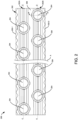
- the plurality of plate fins 200 can be staggered parallelly, such the holes 204 associated with each of the plate fins 200 for receiving the tubes 102 are also staggered or aligned. Further, each of the tubes 102 associated with the heat exchanger coils 100 can extend through the aligned holes 204 of plate fins 200. Referring to FIG. 2 , the plurality of holes 204 can be arranged in one or more rows (202A, 202B) on the plate fin sheet 202, with all the holes 204 in a given row (202A, 202B) having a common centerline (C-C')) that can be oriented parallel to fin edges 202-1, 202-2.
- a fin collar 304 can surround each of the tube holes as shown in detail in FIG. 3 .
- the fin collar 304 can be configured to extend outwardly from the surface of the plate fin 200 in a first direction. By the length to which they extend from the surface of the fin, the plurality of fin collars 304 can serve to determine the spacing (also referred to as fin pitch) between the adjacent plate fins 200 in a given heat exchanger coil 100.
- the plurality of fin collars 304 may also function to ensure that there is a sufficient area of contact and a close mechanical fit, and therefore good thermal conduction, between the plate fins 200 and the tubes 102.
- the plate fin 200 can include a contoured region 302 disposed between adjacent holes 204 in the same row (202A or 202B) on the fin sheet 202.
- the contoured region 302 may include a sinusoidal corrugation or sine-like waveform that runs parallel to the direction of the airflow A and perpendicular to the edges 202-1, 202-2 of the plate fins 200.
- the sinusoidal corrugation 302 can have at least one peak and at least one valley.
- the term 'sinusoidal' is intended to cover waveforms or patterns that may be either true sine curves or approximations of a sine curve. Further, it should be understood that the term 'sinusoidal corrugation' may additionally include waveforms that represent a sine wave with a phase shift, for example resulting in a cosine-like waveform. Design requirements and practical considerations inherent in preparing tooling and manufacturing the fins mean that the waveforms may not necessarily be mathematically precise sine curves.
- the sinusoidal corrugation region 302 in each of the rows (202A, 202B) of the plate fin 200 can include three half-waves (W1 to W3) of a first wave size in the middle portion 302-1 (adjacent to the tube holes) of the corresponding row and two half-waves (W4, W5) of a second wave size on lateral ends 302-2 of the corresponding row with an overall count of 2.5 wave count per row.
- the sinusoidal corrugation 302 can have two peaks and one valley in the middle portion 302-1, and two valleys in the lateral ends 302-2.
- a contoured region 302 including a sinusoidal corrugation extending less wave counts such as a single wave count or 1.5 wave count, or more than 2.5 wave counts are also contemplated herein, and all such embodiments are well within the scope of the invention.
- ⁇ wave size' comprises wavelength and amplitude or height of the corresponding wave formed in the sinusoidal corrugation 302.
- the second wave size of the two half-waves (W4, W5) on the lateral ends 302-2 of the row can be smaller than the first wave size of the three half-waves (W1 to W3) in the middle portion 302-1 of the corresponding row. Accordingly, the sinusoidal corrugation 302 in each row can have two peaks one valley (having a larger wave size) in the middle portion 302-1, and two valleys (having a smaller wave size) in the lateral ends 302-2.
- the wave size of the two half-waves (W4, W5) on lateral ends 302-2 can also be equal to or larger than the wave size of the three half-waves (W1 to W3) in the middle portion 302-1 of the corresponding row, and all such embodiments are within the scope of the invention.
- the amplitude of the two half-waves (W1, W2) on the lateral ends 302-2 of the row can be smaller than the amplitude of the three half-waves (W1 to W3) in the middle portion 302-1 of the corresponding row. Accordingly, the sinusoidal corrugation 302 in each row can have two peaks and one valley (having a larger amplitude) in the middle portion 302-1 and two valleys (having a smaller amplitude) in the lateral ends 302-2.
- the amplitude of the two half-waves (W4, W5) on lateral ends 302-2 can also be equal to or larger than the amplitude of the three half-waves (W1 to W3) in the middle portion 302-1 of the corresponding row, and all such embodiments are within the scope of the invention.
- the sinusoidal corrugations 302 including at least one peak and at least one valley located at the contoured region of the plate fin 200 cannot have a continuous surface. Rather, the contoured region of the plate fin 200 can include at least one elongate lance element 306A, 306B, 306C (collectively designated as 306, herein) created and defined by longitudinal slits 308 formed in the contoured region 302. In a non-limiting embodiment of FIG. 3 , the six longitudinal slits 308 in the contoured region 302 of the plate fin 200 form a total of seven lance elements 306. In other embodiments, as illustrated in FIGs. 4 to 7 , the contoured region 302 can include eleven lance elements 306.
- a contoured region 302 having any suitable number of lance elements 306, such as five lance elements, six lance elements, eight lance elements, nine lance elements, ten lance elements, twelve lance elements, or thirteen lance elements for example, are within the scope of the invention.
- the lance elements 306 can only be located in the middle portion 302-1 of the sinusoidal corrugation regions that are substantially aligned with a portion of the tube hole 204. Accordingly, the waves or valleys on the lateral ends 302-2 of the corrugated region 302 and the inter-row region 206 formed between adjacent tube rows (202A, 202B) do not have any lance elements formed therein. Further, in one or more embodiments, the lance elements 306 can be located in the middle portion 302-1 as well as the lateral ends 302-2 of the sinusoidal corrugation region 302.
- a first portion of the lance elements can be fixed in place along the curvature of the sinusoidal corrugation 302.
- These lance elements are also referred to herein as fixed lance "elements.”
- the second portion of the lance elements can be moved, for example, translated, after formation thereof, such as relative to the mean line of the sinusoidal corrugation, illustrated as the central plane P (see FIGs. 4 to 7 ).
- the lance elements (306A to 306C) that have an adjusted position may also be referred to herein as "adjusted lance elements.”
- the sinusoidal corrugation 302 can include four fixed lance elements and three adjusted lance elements.
- the sinusoidal corrugation 302 can include six fixed lance elements and five adjustable lance elements.
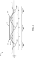
- the plurality of elongate adjustable lance elements 306 can be offset relative to a central plane P arranged at a midpoint of an amplitude of the sinusoidal corrugation 302.
- the central plane P can extend generally through the sinusoidal corrugation 302 at a midpoint of the amplitude or height of the waveform. Accordingly, the distance between the plane P and a peak of the sinusoidal corrugation is equal to the distance between the plane P and a valley of the sinusoidal corrugation.
- at least one adjusted lance element may be offset from the sinusoidal corrugation by a distance (O) referred to as lance offset as exemplified in FIGs. 4 to 7 .
- the plurality of lance elements 306 can have a curved profile such that the lance elements 306 can maintain the curvature of the sinusoidal corrugation 302.
- each of the plurality of elongate lance elements 306 has a cross-sectional shape that is a segment of the sinusoidal corrugation 302.
- the adjustable elongate lance elements 306 may be cut or lanced such that the slits 308 defining the adjustable lance elements 306 are configuration has a generally curved profile.
- the wave count over which the sinusoidal corrugation 302 extends at least partially determines the total number of lance elements 306 included.
- an adjustable lance element 306A arranged at a peak of the sinusoidal corrugation 302 can have a generally concave curvature
- an adjustable lance element 306B, 306C arranged at a valley of the sinusoidal corrugation can have a generally convex curvature
- adjustable lance elements 302 are illustrated as being disposed on opposite sides, at the peaks and valleys, of the sinusoidal corrugation, however, in one or more embodiments (not shown), at least one of the elongate adjustable lance elements among the plurality of elongate adjustable lance elements 306 cannot be present at the peaks or valleys, rather, created at a waveform between the adjacent peak and valley of the sinusoidal corrugated region 302.
- the plurality of lance elements 306 can have a substantially flat profile such that the lance elements 306 can remain substantially tangential to the waveform of the sinusoidal corrugation 302.
- the adjustable elongate lance elements 306 may be cut or lanced such that the slits 308 defining the adjustable lance elements 306 may have a generally planar profile.
- the plurality of lance elements 306 can be inclined such that a non-uniform gap remains between a leading edge and a trailing edge of the corresponding lance element.
- the lance elements 306 may have a planar profile as shown and/or a curved profile (not shown), which may be inclined towards one of the edges.
- the inclined lance elements 306 can be disposed on opposite sides of the peaks and valleys of the sinusoidal corrugation, however, the inclined lance elements 306 cannot be present at the peaks or valleys, rather, can be created at a waveform between the adjacent peak and valley of the sinusoidal corrugated region.
- At least one of the lance elements 306A to 306C among the plurality of elongate adjustable lance elements 306 can be offset such that a first gap created between a leading edge, upstream of airflow direction A, of the corresponding lance elements and a surface of the plate fin 200 is greater than a second gap created between a trailing edge, opposite to the leading edge, of the corresponding lance element 306 and the surface of the plate fin 200.
- These inclined lances elements 306 and profile of the corrugated region 302 can form a jet of the airflow, disrupting the boundary layer and reducing thermal wake effects, thereby enhancing the heat transfer significantly
- the plurality of elongate adjustable lance elements 306 in the corrugated region can have a non-uniform lance width.
- the lance elements 306A associated with waves W1, W3 at the two peaks and the lance element 306B associated with the wave W2 at one valley in the middle portion 302-1 of each row can have the same or different lance widths.
- the lance elements 306C associated with the two waves W4, W5 at the two valleys on the lateral ends 302-2 of each row can have the same or different lance widths.
- the plurality of elongate adjustable lance elements 306 in the corrugated region can have a non-uniform lance offset with respect to the central plane.
- the lance elements 306A, 306B at the two peaks and one valley in the middle portion 302-1 of each row can have the same or different lance offset with respect to the central plane P.
- the lance elements 306C at the two valleys on the lateral ends 302-2 of each row can have the same or different lance offset.
- the width of the lance elements 306C associated with the two half-waves (W4, W5) (having the second wave size) on lateral ends 302-2 of the row can be smaller than the width of the lance elements 306B, 306C associated with the three half-waves (W1 to W3) (having the first wave size) in the middle portion 302-1 of the corresponding row.
- width of lance elements 306C associated with the two half-waves (W4, W5) on lateral ends 302-2 can also be equal or larger than the width of lance elements 306B, 306C associated with the three half-waves (W1 to W3) in the middle portion 302-1 of the corresponding row, and all such embodiments are within the scope of the invention.
- the amplitude of the lance elements 306C associated with the two half-waves (W4, W5) (having the second wave size) on lateral ends 302-2 of the row can be smaller than the amplitude of the lance elements 306B, 306C associated with the three half-waves (W1 to W3) (having the first wave size) in the middle portion 302-1 of the corresponding row.
- the amplitude of lance elements 306C associated with the two half-waves (W4, W5) on lateral ends 302-2 can also be equal or larger than the amplitude of lance elements 306B, 306C associated with the three half-waves (W1 to W3) in the middle portion 302-1 of the corresponding row, and all such embodiments are within the scope of the invention.
- At least one of the adjusted lance elements 306A to 306C can be moved in a downward direction, beyond a lower surface of the plate fin 200.
- This downward direction is a second direction, opposite the first direction in which the fin collar 304 extends from the plate fin 200.
- each of the adjusted lance elements originated 306B, 306C from a valley of the sinusoidal corrugation 302 can be moved downwardly away from plane P, such that an upper surface of the lance element 306B, 306C is positioned vertically beneath a lower surface of the plate fin 200.
- the distance between the lance element 306B, 306C and the plane P increases.
- each of the lance elements 306A originating from a peak of the sinusoidal corrugation 302 may be similarly moved in the same second, downward direction such that an upper surface of the lance element 306A is positioned vertically beneath the lower surface of the plate fin 200.
- the downward movement can move the lance elements 306A toward the plane P such that the distance between the lance elements 306A and the plane P decreases. Accordingly, the distance between the plane P and the lance elements 306B, 306C can be different than the distance between the lance elements 306A and the plane P.
- the distance by which adjacent lance elements 306A to 306C are offset from the sinusoidal corrugation, 302 in a direction perpendicular to the direction of flow A, such as relative to the plane P for example, also referred to herein as the lance offset, may be uniform.
- At least one lance element 306B, 306C arranged at a valley of the sinusoidal corrugation can be moved in an opposite direction as at least one lance element 306A arranged at a peak of the sinusoidal corrugation 302.
- each of the lance elements 306B, 306C arranged at a valley of the sinusoidal corrugation 302 can be moved in the second direction, downwardly away from plane P.
- an upper surface of the lance element 306B, 306C can be positioned vertically beneath the lower surface of the plate fin 200. Because of this movement, the distance between the lance element 306B, 306C, and the plane P can increase.
- each of the lance elements 306A formed at a peak of the sinusoidal corrugation can be moved in the first, upward direction in which the fin 200 collar extends from the plate fin 200.
- the lower surface of the lance element 306A may be positioned vertically above the upper surface of the plate fin 200.
- the total distance that each lance element (306A to 306C) can be moved in a direction perpendicular to the direction of flow A, such as relative to the plane P for example may be equal or may vary.
- the plurality of elongate adjustable lance elements (306A to 306C) can be offset relative to a central plane P arranged at a midpoint of an amplitude of the sinusoidal corrugation 302. As shown, each of the adjusted lance elements 306B, 306C originating from a valley of the sinusoidal corrugation can be moved upwardly towards the central plane P, such that the bottom surface of the corresponding lance element 306B, 306C is positioned vertically above a lower surface of the plate fin 200.
- each of the lance elements 306A originating from a peak of the sinusoidal corrugation may be similarly moved in the downward direction such that an upper surface of the corresponding lance element 306A is positioned vertically beneath the lower surface of the plate fin 200. As a result of this movement, the distance between the lance elements (306A to 306C) and the plane P decreases.
- the profile of the corrugated region and the lance elements in the plate fin can form the jet of the airflow, disrupting the boundary layer and reducing thermal wake effects, thereby enhancing heat transfer significantly.
- this, invention improves and optimizes the geometry of the existing lanced fins used in heat exchangers, by enhancing the heat transfer process and the overall performance of the heat exchanger while keeping the overall cost of manufacturing the plate fin lower.
Landscapes
- Engineering & Computer Science (AREA)
- Physics & Mathematics (AREA)
- Thermal Sciences (AREA)
- Mechanical Engineering (AREA)
- General Engineering & Computer Science (AREA)
- Geometry (AREA)
- Heat-Exchange Devices With Radiators And Conduit Assemblies (AREA)
Priority Applications (1)
| Application Number | Priority Date | Filing Date | Title |
|---|---|---|---|
| EP25188224.7A EP4614103A3 (fr) | 2023-11-10 | 2024-11-08 | Configuration d'ailettes à onde sinusoïdale en forme de lance pour échangeurs de chaleur |
Applications Claiming Priority (1)
| Application Number | Priority Date | Filing Date | Title |
|---|---|---|---|
| US202363597761P | 2023-11-10 | 2023-11-10 |
Related Child Applications (2)
| Application Number | Title | Priority Date | Filing Date |
|---|---|---|---|
| EP25188224.7A Division EP4614103A3 (fr) | 2023-11-10 | 2024-11-08 | Configuration d'ailettes à onde sinusoïdale en forme de lance pour échangeurs de chaleur |
| EP25188224.7A Division-Into EP4614103A3 (fr) | 2023-11-10 | 2024-11-08 | Configuration d'ailettes à onde sinusoïdale en forme de lance pour échangeurs de chaleur |
Publications (2)
| Publication Number | Publication Date |
|---|---|
| EP4553435A1 true EP4553435A1 (fr) | 2025-05-14 |
| EP4553435B1 EP4553435B1 (fr) | 2026-03-25 |
Family
ID=93460884
Family Applications (2)
| Application Number | Title | Priority Date | Filing Date |
|---|---|---|---|
| EP24211928.7A Active EP4553435B1 (fr) | 2023-11-10 | 2024-11-08 | Configuration d'ailettes à onde sinusoïdale en forme de lance pour échangeurs de chaleur |
| EP25188224.7A Pending EP4614103A3 (fr) | 2023-11-10 | 2024-11-08 | Configuration d'ailettes à onde sinusoïdale en forme de lance pour échangeurs de chaleur |
Family Applications After (1)
| Application Number | Title | Priority Date | Filing Date |
|---|---|---|---|
| EP25188224.7A Pending EP4614103A3 (fr) | 2023-11-10 | 2024-11-08 | Configuration d'ailettes à onde sinusoïdale en forme de lance pour échangeurs de chaleur |
Country Status (3)
| Country | Link |
|---|---|
| US (1) | US20250155202A1 (fr) |
| EP (2) | EP4553435B1 (fr) |
| CN (1) | CN119983905A (fr) |
Families Citing this family (1)
| Publication number | Priority date | Publication date | Assignee | Title |
|---|---|---|---|---|
| CN116772640A (zh) * | 2022-03-15 | 2023-09-19 | 开利公司 | 高性能锯齿正弦波翅片构造 |
Citations (7)
| Publication number | Priority date | Publication date | Assignee | Title |
|---|---|---|---|---|
| EP0325553A1 (fr) * | 1988-01-11 | 1989-07-26 | Carrier Corporation | Ailette ondulée |
| US4860822A (en) * | 1987-12-02 | 1989-08-29 | Carrier Corporation | Lanced sine-wave heat exchanger |
| US5111876A (en) * | 1991-10-31 | 1992-05-12 | Carrier Corporation | Heat exchanger plate fin |
| US5168923A (en) * | 1991-11-07 | 1992-12-08 | Carrier Corporation | Method of manufacturing a heat exchanger plate fin and fin so manufactured |
| US6786274B2 (en) * | 2002-09-12 | 2004-09-07 | York International Corporation | Heat exchanger fin having canted lances |
| JP5422743B2 (ja) * | 2009-08-11 | 2014-02-19 | トレイン・インターナショナル・インコーポレイテッド | ルーバ付きプレートフィン |
| CN116772640A (zh) * | 2022-03-15 | 2023-09-19 | 开利公司 | 高性能锯齿正弦波翅片构造 |
-
2024
- 2024-11-01 US US18/934,867 patent/US20250155202A1/en active Pending
- 2024-11-08 CN CN202411591049.9A patent/CN119983905A/zh active Pending
- 2024-11-08 EP EP24211928.7A patent/EP4553435B1/fr active Active
- 2024-11-08 EP EP25188224.7A patent/EP4614103A3/fr active Pending
Patent Citations (7)
| Publication number | Priority date | Publication date | Assignee | Title |
|---|---|---|---|---|
| US4860822A (en) * | 1987-12-02 | 1989-08-29 | Carrier Corporation | Lanced sine-wave heat exchanger |
| EP0325553A1 (fr) * | 1988-01-11 | 1989-07-26 | Carrier Corporation | Ailette ondulée |
| US5111876A (en) * | 1991-10-31 | 1992-05-12 | Carrier Corporation | Heat exchanger plate fin |
| US5168923A (en) * | 1991-11-07 | 1992-12-08 | Carrier Corporation | Method of manufacturing a heat exchanger plate fin and fin so manufactured |
| US6786274B2 (en) * | 2002-09-12 | 2004-09-07 | York International Corporation | Heat exchanger fin having canted lances |
| JP5422743B2 (ja) * | 2009-08-11 | 2014-02-19 | トレイン・インターナショナル・インコーポレイテッド | ルーバ付きプレートフィン |
| CN116772640A (zh) * | 2022-03-15 | 2023-09-19 | 开利公司 | 高性能锯齿正弦波翅片构造 |
Also Published As
| Publication number | Publication date |
|---|---|
| EP4614103A3 (fr) | 2025-11-12 |
| EP4614103A2 (fr) | 2025-09-10 |
| EP4553435B1 (fr) | 2026-03-25 |
| US20250155202A1 (en) | 2025-05-15 |
| CN119983905A (zh) | 2025-05-13 |
Similar Documents
| Publication | Publication Date | Title |
|---|---|---|
| EP0319451B1 (fr) | Echangeur de chaleur à ailettes sinusoidales perforées | |
| EP1653185B1 (fr) | Echangeur de chaleur | |
| JP4207331B2 (ja) | 複式熱交換器 | |
| US9395121B2 (en) | Heat exchanger having convoluted fin end and method of assembling the same | |
| JPH08510047A (ja) | ひれ付き管式熱交換器 | |
| US20120066905A1 (en) | Heat exchanger having a contoured insert and method of assembling the same | |
| US20130277029A1 (en) | Heat Transfer Surfaces With Flanged Apertures | |
| US5318112A (en) | Finned-duct heat exchanger | |
| JPH03181796A (ja) | 熱交換器のプレートフィン構造 | |
| EP4553435A1 (fr) | Configuration d'ailettes à onde sinusoïdale en forme de lance pour échangeurs de chaleur | |
| JP2004517293A (ja) | ろう付け板を有する熱交換器 | |
| US12529530B2 (en) | High performance lanced sine wave fin configuration | |
| JPH0481108B2 (fr) | ||
| US5062474A (en) | Oil cooler | |
| JP2011089664A (ja) | 熱交換器用コルゲートフィンの製造方法 | |
| CA1069883A (fr) | Echangeur de chaleur a surface primaire compacte | |
| EP3301393B1 (fr) | Échangeur de chaleur | |
| KR20110083016A (ko) | 열 교환기용 핀 및 이를 갖는 열 교환기 | |
| JP3749436B2 (ja) | 中断された回旋を具えた熱交換器用乱流化装置 | |
| US5476140A (en) | Alternately staggered louvered heat exchanger fin | |
| EP2064509B1 (fr) | Surfaces de transfert de chaleur dotées d'ouvertures à brides | |
| JPH01310297A (ja) | 熱交換器用プレートフィン及びフィンチューブ型熱交換器 | |
| CA1239927A (fr) | Dispositif de transfert thermique pousse pour echangeurs de chaleur a tubes plats et ailettes | |
| JP3203606B2 (ja) | 熱交換器 | |
| JP2025535527A (ja) | 熱交換プレートおよびプレート熱交換器 |
Legal Events
| Date | Code | Title | Description |
|---|---|---|---|
| PUAI | Public reference made under article 153(3) epc to a published international application that has entered the european phase |
Free format text: ORIGINAL CODE: 0009012 |
|
| STAA | Information on the status of an ep patent application or granted ep patent |
Free format text: STATUS: THE APPLICATION HAS BEEN PUBLISHED |
|
| AK | Designated contracting states |
Kind code of ref document: A1 Designated state(s): AL AT BE BG CH CY CZ DE DK EE ES FI FR GB GR HR HU IE IS IT LI LT LU LV MC ME MK MT NL NO PL PT RO RS SE SI SK SM TR |
|
| STAA | Information on the status of an ep patent application or granted ep patent |
Free format text: STATUS: REQUEST FOR EXAMINATION WAS MADE |
|
| 17P | Request for examination filed |
Effective date: 20250623 |
|
| GRAP | Despatch of communication of intention to grant a patent |
Free format text: ORIGINAL CODE: EPIDOSNIGR1 |
|
| STAA | Information on the status of an ep patent application or granted ep patent |
Free format text: STATUS: GRANT OF PATENT IS INTENDED |
|
| INTG | Intention to grant announced |
Effective date: 20251015 |
|
| GRAS | Grant fee paid |
Free format text: ORIGINAL CODE: EPIDOSNIGR3 |
|
| GRAA | (expected) grant |
Free format text: ORIGINAL CODE: 0009210 |
|
| STAA | Information on the status of an ep patent application or granted ep patent |
Free format text: STATUS: THE PATENT HAS BEEN GRANTED |
|
| AK | Designated contracting states |
Kind code of ref document: B1 Designated state(s): AL AT BE BG CH CY CZ DE DK EE ES FI FR GB GR HR HU IE IS IT LI LT LU LV MC ME MK MT NL NO PL PT RO RS SE SI SK SM TR |
|
| REG | Reference to a national code |
Ref country code: CH Ref legal event code: F10 Free format text: ST27 STATUS EVENT CODE: U-0-0-F10-F00 (AS PROVIDED BY THE NATIONAL OFFICE) Effective date: 20260325 Ref country code: GB Ref legal event code: FG4D |
|
| REG | Reference to a national code |
Ref country code: DE Ref legal event code: R096 Ref document number: 602024003447 Country of ref document: DE |
|
| REG | Reference to a national code |
Ref country code: IE Ref legal event code: FG4D |