EP4553607A1 - Bedienelement für eine maschine - Google Patents
Bedienelement für eine maschine Download PDFInfo
- Publication number
- EP4553607A1 EP4553607A1 EP23208550.6A EP23208550A EP4553607A1 EP 4553607 A1 EP4553607 A1 EP 4553607A1 EP 23208550 A EP23208550 A EP 23208550A EP 4553607 A1 EP4553607 A1 EP 4553607A1
- Authority
- EP
- European Patent Office
- Prior art keywords
- lever
- torque
- restoring
- modifying
- guiding surface
- Prior art date
- Legal status (The legal status is an assumption and is not a legal conclusion. Google has not performed a legal analysis and makes no representation as to the accuracy of the status listed.)
- Withdrawn
Links
Images



Classifications
-
- G—PHYSICS
- G05—CONTROLLING; REGULATING
- G05G—CONTROL DEVICES OR SYSTEMS INSOFAR AS CHARACTERISED BY MECHANICAL FEATURES ONLY
- G05G5/00—Means for preventing, limiting or returning the movements of parts of a control mechanism, e.g. locking controlling member
- G05G5/03—Means for enhancing the operator's awareness of arrival of the controlling member at a command or datum position; Providing feel, e.g. means for creating a counterforce
-
- G—PHYSICS
- G05—CONTROLLING; REGULATING
- G05G—CONTROL DEVICES OR SYSTEMS INSOFAR AS CHARACTERISED BY MECHANICAL FEATURES ONLY
- G05G5/00—Means for preventing, limiting or returning the movements of parts of a control mechanism, e.g. locking controlling member
- G05G5/05—Means for returning or tending to return controlling members to an inoperative or neutral position, e.g. by providing return springs or resilient end-stops
-
- G—PHYSICS
- G05—CONTROLLING; REGULATING
- G05G—CONTROL DEVICES OR SYSTEMS INSOFAR AS CHARACTERISED BY MECHANICAL FEATURES ONLY
- G05G1/00—Controlling members, e.g. knobs or handles; Assemblies or arrangements thereof; Indicating position of controlling members
- G05G1/04—Controlling members for hand actuation by pivoting movement, e.g. levers
-
- G—PHYSICS
- G05—CONTROLLING; REGULATING
- G05G—CONTROL DEVICES OR SYSTEMS INSOFAR AS CHARACTERISED BY MECHANICAL FEATURES ONLY
- G05G9/00—Manually-actuated control mechanisms provided with one single controlling member co-operating with two or more controlled members, e.g. selectively, simultaneously
- G05G9/02—Manually-actuated control mechanisms provided with one single controlling member co-operating with two or more controlled members, e.g. selectively, simultaneously the controlling member being movable in different independent ways, movement in each individual way actuating one controlled member only
- G05G9/04—Manually-actuated control mechanisms provided with one single controlling member co-operating with two or more controlled members, e.g. selectively, simultaneously the controlling member being movable in different independent ways, movement in each individual way actuating one controlled member only in which movement in two or more ways can occur simultaneously
- G05G9/047—Manually-actuated control mechanisms provided with one single controlling member co-operating with two or more controlled members, e.g. selectively, simultaneously the controlling member being movable in different independent ways, movement in each individual way actuating one controlled member only in which movement in two or more ways can occur simultaneously the controlling member being movable by hand about orthogonal axes, e.g. joysticks
- G05G2009/04766—Manually-actuated control mechanisms provided with one single controlling member co-operating with two or more controlled members, e.g. selectively, simultaneously the controlling member being movable in different independent ways, movement in each individual way actuating one controlled member only in which movement in two or more ways can occur simultaneously the controlling member being movable by hand about orthogonal axes, e.g. joysticks providing feel, e.g. indexing means, means to create counterforce
-
- G—PHYSICS
- G05—CONTROLLING; REGULATING
- G05G—CONTROL DEVICES OR SYSTEMS INSOFAR AS CHARACTERISED BY MECHANICAL FEATURES ONLY
- G05G9/00—Manually-actuated control mechanisms provided with one single controlling member co-operating with two or more controlled members, e.g. selectively, simultaneously
- G05G9/02—Manually-actuated control mechanisms provided with one single controlling member co-operating with two or more controlled members, e.g. selectively, simultaneously the controlling member being movable in different independent ways, movement in each individual way actuating one controlled member only
- G05G9/04—Manually-actuated control mechanisms provided with one single controlling member co-operating with two or more controlled members, e.g. selectively, simultaneously the controlling member being movable in different independent ways, movement in each individual way actuating one controlled member only in which movement in two or more ways can occur simultaneously
- G05G9/047—Manually-actuated control mechanisms provided with one single controlling member co-operating with two or more controlled members, e.g. selectively, simultaneously the controlling member being movable in different independent ways, movement in each individual way actuating one controlled member only in which movement in two or more ways can occur simultaneously the controlling member being movable by hand about orthogonal axes, e.g. joysticks
Definitions
- the present invention relates to an operating element for controlling a function of a machine, in particular of a mobile machine, such as a vehicle, and to a method of operating such operating element.
- Mobile machines such as agricultural or construction vehicles, often comprise a plurality of different functionalities that need to be controlled. This may comprise controlling the movement of the vehicle itself and controlling different functions of such vehicle, such as an excavator arm or an agricultural tool.
- a respective mobile machine may accordingly comprise a plurality of different operating elements, such as levers (e.g. in the form of joysticks), switches, buttons, and the like. The space requirement of such large number of operating elements is excessive.
- the first guiding surface is shaped to cause the restoring force application element to apply a force to the first guiding surface to generate the restoring torque when the lever is pivoted.
- the torque-modifying assembly comprises a second guiding element and a modifying force application element having a second contact part.
- the second contact part is arranged to move on a second guiding surface of the second guiding element when the lever is pivoted.
- the second guiding surface is shaped to cause the modifying force application element to apply a force to the second guiding surface to generate the modifying torque when the lever is pivoted.
- the first guiding surface is spatially separate and distinct from the second guiding surface.
- Such configuration may provide a compact operating element having a high degree of functionality.
- several types of haptic feedback may be implemented which facilitates an intuitive operation of the operating element by the user and makes the operating element suitable for controlling a variety of functions of the machine.
- the first guiding element may for example have a simpler structure and may be placed closer to the rotating axis, thus decreasing the installation depth of the operating element.
- the separate second guiding surface may be shaped so as to provide a dedicated torque characteristic when operating the lever.
- the operating element may be equipped with different types, in particular different shapes, of the second guiding surface, thus allowing an adaptation of the torque characteristic.
- the versatility of the operating element may thereby be improved.
- different shapes of the second guiding surface may be mounted at the end of the assembly of the operating element, thus being capable of providing operating elements with different torque characteristics in a standardized assembly process and with a standardized form factor.
- the operating element may only comprise the restoring assembly, and the torque-modifying assembly is only optional.
- the restoring assembly may have any of the configurations disclosed herein.
- only the torque-modifying assembly may be provided, and the restoring assembly is optional.
- the torque-modifying assembly may have any of the configurations described herein.
- the operating element may comprise a housing, and the lever may be pivotable relative to such housing.
- the respective torque may in particular be applied to the lever with respect to the housing, e.g. it may act between the housing and the lever.
- the operating element may be a single axis or multi-axes operating element.
- the operating element may be a respective joystick.
- the first and second guiding surfaces may be arranged on the same side of the rotational axis, in particular on the same side of a plane that includes the rotational axis when the lever is in the initial position.
- both guiding surfaces may be arranged on one side of a plane that includes the rotational axis, and a handle of the lever may be arranged on the other side of the plane.
- the first guiding element and the second guiding element may be arranged on the same side of a plane that includes the rotational axis.
- first guiding surface and the second guiding surface may be arranged on different sides of a plane that is parallel to the rotation axis when the lever is in the initial position.
- this plane may further be perpendicular to a direction of extension of the lever or to a direction of force application by the restoring force application element when the lever is in the initial position.
- the guiding surfaces may thus not interfere with each other.
- One of the first guiding surface and the second guiding surface may be stationary with respect to a housing of the operating element, and the other of the first guiding surface and the second guiding surface may be coupled to the lever to move with the lever.
- the second guiding surface is shaped so as to generate a modifying torque that provides one or a combination of the following: A pressure point that has to be overcome when pivoting the lever; a locked position different from the initial position in which the lever is locked after being released; and/or a default position for which the modifying torque has to be overcome for moving the lever out of the default position.
- Such default position may be the initial position of the lever, for example an equilibrium position.
- the locked position may for example be a position at which the lever is latched or snapped in; the user may for example pivot the lever into the locked position and release the lever, upon which the lever remains in the locked position.
- the second guiding surface may be shaped so as to provide a pressure point.
- a float position of the hydraulic system may for example be reached. The user of the operating element can thus reliably determine when the float position is reached.
- the lever may be pivotable in two opposing directions (e.g. back and forth), and the modifying torque generated by the torque-modifying assembly may be the same or may be different for the different directions of operation of the lever.
- Different modifying torques may be achieved by different shapes of the second guiding surface for the different directions of movement of the second contact part on the second guiding surface, e.g. starting from the initial position.
- a pressure point may be symmetrically provided on each side, or two or more pressure points may be provided on at least one side, or one side of the second guiding surface may not generate any modifying torque.
- Other examples and combinations are of course conceivable.
- the first guiding element or the at least one restoring force application element may be coupled, in particular mounted, to the lever and may be pivoted with the lever.
- the first guiding element is coupled to the lever to pivot with the lever, for example mounted to a shaft that rotates when pivoting the lever.
- the modifying force application element or the second guiding element may be coupled, in particular mounted, to the lever and may be pivoted with the lever.
- the modifying force application element is coupled to the lever and pivots with the lever.
- the first guiding element is coupled to the lever to pivot with the lever and the modifying force application element is mounted to the first guiding element.
- a compact configuration may thereby be achieved.
- the coupling to the lever may be an indirect coupling.
- the lever may be supported by a gimbal mount, and the respective first guiding element or second guiding element may be mounted to a shaft of the gimbal mount (e.g., to a stub shaft) that rotates with the lever when the lever is pivoted.
- the arrangement may be such that the first guiding surface faces the rotational axis.
- a distance of the first guiding surface from the rotational axis may be smaller than a distance of the rotational axis to an end of a housing of the operating element, the distance being taken in the direction of the lever.
- the first guiding element may be mounted close to the rotational axis, thereby achieving a compact configuration.
- the restoring assembly may comprise two restoring force application elements arranged on opposite sides of the rotation axis. Each restoring force application element may apply a force to the first guiding surface to generate a restoring torque on the lever.
- the restoring torque generated by a first of the two restoring force application elements may be opposite to a restoring torque generated by a second of the two restoring force application elements.
- the first guiding surface may for example be shaped such that the restoring torque acting to the restore the lever to the initial position is larger than the opposite restoring torque when the lever is moved out of the initial position. The restoring torque may thus safely return the lever to the initial position.
- the first and the second restoring force application elements may be pre-tensioned to apply a restoring torque of a similar (or of the same) magnitude when the lever is in the initial position.
- the initial position may accordingly be an equilibrium position in which both restoring torques offset each other.
- Such pre-tensioning may have the advantage of a very well defined initial position, and may further cause that the torque that needs to be applied to move the lever out of the initial position raises rather steeply. This reduces the play of the lever in the initial position and may essentially eliminate such central play.
- the lever will thus be centered reliably at the initial position, which improves the haptic feedback for the operator and in particular allows the operator to determine whether the lever has actually been actuated or not.
- the first guiding surface may have a shape that at least partly surrounds the first contact part of each of the two restoring force application elements.
- Each restoring force application element may comprise a spring acting on the respective first contact part, in particular pushing the first contact part, to cause the first contact part to apply the force to the first guiding surface.
- the spring may be a coil spring.
- the spring may have one end supported by a housing of the operating element; the end may rest against a housing part.
- such housing part may have a protrusion that is inserted into the coil spring and that provides guidance for the coil spring when the coil spring is being compressed or expanded.
- the first contact part may be supported by a shaft (e.g. an axle) that is movably supported in a housing of the operating element.
- the first contact part may for example be a roller that rolls on the first guiding surface.
- the housing comprises a mount, and a shaft of the first contact part is supported in the mount.
- the mount may be configured to allow movement of the shaft in one dimension, in particular perpendicular to an axial direction of the shaft. For example, it may allow movement in a direction parallel to a direction of extension of a spring of the restoring force application element.
- the first contact part may thus stay in contact with the spring and can move in axial direction of the spring when the spring is being compressed or expanded.
- the direction of extension of the spring may in particular be a central axial direction of a coil spring (i.e., the central axis of the cylindrical shape).
- the mount may for example be a slot or recess in the housing, wherein the slot or recess extends in the respective direction of the spring. It may also be formed by parallel ridges or ribs that are provided on a part or on a wall of the housing.
- Such contact part may provide an efficient torque application while at the same time may reduce the frictional resistance of the pivoting movement of the lever
- the modifying force-generating element comprises a spring, wherein the spring is arranged to push the second contact part onto the second guiding surface to apply the force to the second guiding surface.
- the second guiding surface may be shaped to change a spring loading of the spring when the lever is pivoted about the rotational axis to generate the modifying torque.
- the modifying force-generating element may for example comprise a flat spring, in particular a sheet metal spring.
- a flat spring in particular a sheet metal spring.
- the second contact part may be formed by a protrusion of the spring. It may in particular be integral with the spring.
- a flat spring or a sheet metal spring may have a shape that forms such protrusion that bulges outwardly, for example at a central position where two spring arms meet.
- the modifying force-generating element may thus consist of a single part, the complexity of the operating element may further be reduced.
- the protrusion may for example slide on the second guiding surface when the lever is pivoted. Accordingly, the shape of the second guiding surface results in different compression of the respective flat or sheet metal spring, and thus in different modifying torques applied to the lever.
- the second guiding surface is shaped to provide one or a combination of the following:
- the guiding surface may be shaped so as to provide a combination of respective functionalities; it may for example provide a respective recess for defining a default position and may provide a pressure point and/or locked position on one or on both sides thereof.
- the second guiding element may be a distinct part that is mounted in a replaceable or exchangeable manner to a side of a housing of the operating element. It may for example be mounted to a lower side opposite to an upper side from which the lever protrudes. This may facilitate defining the torque characteristic of the operating element in a final assembly step in which the respective second guiding element is mounted. Further it may facilitate changing the torque characteristic by exchanging the second guiding element. It may in particular allow an on-site adaptation of the functionality of the operating element. The flexibility may thereby be increased significantly and the effort required to change the characteristics of the operating element may be reduced.
- the second guiding element may for example be shaped as a plate or frame.
- the second guiding element may be configured to be mountable in two orientations to the housing of the operating element.
- the second guiding element may have two different second guiding surfaces, and in each orientation, a different second guiding surface may interact with the modifying force application element.
- the torque characteristic of the operating element may thus simply be changed by rotating the second guiding element. It may for example be mounted by one, two or more screws to the housing of the operating element so that it can easily be exchanged or rotated.
- the lever is pivotable about a second rotational axis, in particular perpendicular to the first rotational axis. It may thus implement a multi-axes operating element.
- the second guiding element may have a further second guiding surface for generating a modifying torque that is applied to the lever when the lever is pivoted about the second rotational axis.
- a single second guiding element may thus define in a simple and independent manner the torque characteristic for both pivoting directions of the lever, thereby providing a compact and simple mechanical configuration.
- the operating element may for example comprise a second restoring assembly configured to apply a restoring torque to the lever about the second rotational axis to return the lever to a second initial position and a second torque-modifying assembly configured to apply a modifying torque to the lever about the second rotational axis to modify a torque required to pivot the lever about the second rotational axis.
- a respective assembly for generating the restoring torque and the modifying torque may thus be provided.
- either one of the restoring assembly and the torque-modifying assembly is optional, so that the operating element may only comprise a second restoring assembly or a second torque-modifying assembly.
- the second restoring assembly may have any configuration disclosed herein with respect to the first mentioned restoring assembly.
- the second torque-modifying assembly may have any configuration disclosed herein with respect to the first mentioned torque-modifying assembly. Accordingly, similar advantages may also be achieved for the second pivoting direction of the lever.
- the lever may for example be mounted by a gimbal mount having two shafts that are rotated about the respective rotational axes when the lever is pivoted in the respective direction.
- a component of the respective restoring assembly and a component of the respective torque-modifying assembly may be mechanically coupled or mounted to the respective shaft to pivot with the shaft when the shaft is rotated by pivoting the lever.
- Such gimbal mount may also be termed "cardan suspension”.
- the operating element may thus have a rather symmetric configuration for the two different pivoting directions, thus further simplifying the mechanical configuration.
- a machine in particular a mobile machine, such as a construction vehicle, an agricultural vehicle, or an industrial vehicle, is provided.
- the machine comprises an operating element having any of the configurations described herein, wherein the operating element is arranged to control at least one function of the machine.
- a method of operating an operating element having any of the configurations described herein comprises pivoting the lever from the initial position about the rotational axis, thereby generating a restoring torque on the lever by means of the restoring assembly and generating a modifying torque on the lever by means of the torque-modifying assembly.
- only one of the restoring assembly and the torque-modifying assembly may be provided, and the method may be adapted accordingly.
- Fig. 1 shows a sectional view of an embodiment of an operating element 10.
- the lever 11 of operating element 10 is pivotable with respect to a housing 15 of operating element 10.
- Lever 11 may be suspended by a shaft 13 rotatable about the rotational axis 12.
- Housing 15 may be adapted to the size of the available installation space and may have any of the known configurations; details are omitted here for the sake of a compact presentation.
- Operating element 10 includes a restoring assembly 20 for restoring lever 11 into an initial or default position, which may be the position shown in Fig. 1 .
- Restoring assembly 20 has a first guiding element 21 that is coupled to lever 11 and therefore pivots with the lever 11.
- First guiding element 21 may be mounted to an end of lever 11 (for a single axis operating element) or may be mounted directly or indirectly to the shaft 13 that rotates when lever 11 is pivoted.
- First guiding element 21 includes a guiding surface 22 that faces the rotation axis 12.
- the first guiding element 21 and its guiding surface 22 extend symmetrically in a lateral direction perpendicular to the direction in which lever 11 extends. Consequently, when lever 11 is pivoted, the distance of the guiding surface 22 to the walls of housing 15 changes.
- the restoring assembly 20 further includes two restoring force application elements 30 that are mounted to the housing 15 on opposite sides of the rotation axis 12.
- Each restoring force application element 30 includes a first contact part 31 that is pushed into contact with the first guiding surface 22. It further comprises a spring 32, in particular a coil spring, that applies the pushing force to the contact part 31 to apply a respective force via contact part 31 to the first guiding surface 22.
- Housing 15 may comprise a protrusion or support 16 that is inserted into spring 32 and that supports and guides spring 32 when it is being compressed or expanded.
- Spring 32 and protrusion 16 extend in a direction perpendicular to rotational axis 12 and substantially parallel to the extension of lever 11 in the initial or default position. In particular, they extend from an upper side of housing 15, from which the lever 11 extends, downwardly towards the first guiding surface 22.
- a torque characteristic of the restoring torque can be adapted. In particular, it may be determined how steeply the torque rises when the lever is pivoted out of its initial position, and how the restoring torque changes along the pivoting range.
- the first contact part 31 may be a roller that is supported by a shaft 33 and that rotates about the shaft. Friction may thereby be reduced, making operation of lever 11 smoother.
- the housing 15 may be provided with a mount that allows a respective movement of shaft 33.
- the mount may in particular allow a one-dimensional movement of shaft 33 in a direction perpendicular to the rotational axis of shaft 33 and essentially parallel to the direction in which spring 32 is compressed and expanded.
- Fig. 3 illustrates an exemplary implementation of mount 17.
- Mount 17 is provided as an elongated recess or slit in a wall of housing 15 in which an end of shaft 33 is guided.
- Fig. 3 illustrates on the left-hand side a situation in which the left-hand spring is expanded (shaft 33 on bottom of slot) and the right-hand spring is compressed (shaft 33 in the upper part of slot 17), similar to the situation in Fig. 2 . Note that this only schematically illustrates the different positions that shaft 33 can take, which do not correspond to the position of lever 11 in Fig. 3 .
- the springs 32 on opposite sides of rotation axis 12 are pre-tensioned so that in the initial position of Fig. 1 , a force is applied to the guiding surface 22 on either side of the rotational axis 12.
- the configuration may be symmetric about a plane through the rotational axis 12 (in the default position, the configuration is mirror symmetric about a plane including rotation axis 12 and a central axis of lever 11).
- the applied forces may thus be similar, and similar restoring torques acting in opposite directions may thus be applied to lever 11. Accordingly, lever 11 is maintained in the equilibrium position, corresponding to the initial position. Due to the pre-tensioning, the play of lever 11 in such initial position is reduced significantly, and a well-defined initial position providing improved haptic feedback can be provided.
- Operating element 10 further comprises a torque-modifying assembly 40 that generates a torque acting on lever 11 when the lever 11 is pivoted.
- Assembly 40 includes a second guiding element 41 on which a second contact part 51 of a modifying force application element 50 is guided and is moved when the lever 11 is pivoted.
- the second guiding surface 42 of second guiding element 41 is separate from the first guiding surface 22. Accordingly, the modifying torque, which may for example provide haptic feedback, can be adjusted and generated independently from the restoring torque.
- Modifying force application element 50 is provided in form of a flat spring 52 that is bent to form a protrusion which provides the second contact part 51.
- Spring 52 is mounted to the first guiding element 21 and therefore pivots together with lever 11 about the rotational axis 12.
- the second guiding surface 42 includes recesses and/or protrusions, which have to be overcome when the second contact part 51 is moved along guiding surface 42.
- a force is required to move the contact part 51 out of a recess or over a protrusion, a respective torque or force needs to be applied to lever 11.
- Interaction of spring 52 and guiding surface 42 therefore results in a modification of the torque characteristics of lever 11 and to the application of a corresponding modifying torque to the lever 11 that has to be overcome for moving the lever.
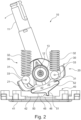
- the guiding surface 42 includes a recess 45 positioned such that the second contact part 51 engages recess 45 when the lever is in the initial position, as shown in Fig. 1 .
- additional torque has to be applied to move second contact part 51 out of the recess, the play of lever 11 in the initial position is reduced and the operating element holds lever 11 more stably in the initial position.
- Guiding surface 42 further includes a protrusion 46 that requires additional torque to be applied to lever 11 to cause the contact part 51 to overcome the protrusion 46. Once the protrusion 46 is overcome, the torque required to move the lever is again lower. A user pivoting the lever will accordingly feel the required torque that needs to by applied (i.e. a pressure point) and will thus obtain haptic feedback when moving the lever.
- Fig. 2 shows the lever in a position in which the second contact part 51 has overcome the protrusion 46. If the user now releases the lever, and the modifying torque generated by protrusion 46 is lower than the restoring torque generated by restoring assembly 20, the lever will return to its initial position. By increasing the size of protrusion 46, the torque required to overcome protrusion 46 may be larger than the restoring torque, so that the lever 11 will retain its pivoted position if released. This accordingly corresponds to a locked position at which lever 11 is locked or latched. By adapting the shape of the second guiding surface 42, it thus becomes possible to implement different functionalities for the operating element 10. In the example of Figs. 1 and 2 , a single pressure point 46 is provided on one side of the initial position (at recess 45).
- second guiding surface 42 does not comprise any recesses or protrusions, so that the torque is not modified.
- the second guiding surface 42 may have the same shape on either side of the initial position 45.
- One, two or more pressure points and/or one, two or more locked positions may be provided on one or on either side of the initial position. Recess 45 at the initial position is optional. Instead of using a protrusion, a pressure point may also be provided with a recess. Likewise, a locked position may be provided with a (deeper) recess.
- the second guiding element 41 may be a component that is mounted to the housing 15, e.g. to a side thereof, in particular to a lower side thereof opposite to the side from which lever 11 extends. It may thus easily be exchanged, so that the torque profile of lever 11 can be adapted to the required functionality.
- the guiding element 42 may be screwed by one, more or two screws 19 to the housing 15 or may otherwise be fastened thereto ( Fig. 5 ).
- Figs. 1 and 2 illustrate the pivoting of lever 11 about one rotational axis 12; operating element 10 may be implemented as a single axis operating element, e.g. joystick. It may further be implemented as a multi-axes operating element having for example a first rotational axis 12-1 and a second rotational axis 12-2 about which the lever 11 can be rotated, as illustrated in Fig. 3 .
- Lever 11 may be mounted by a gimbal mount suspended by two respective rotational shafts 13-1 and 13-2, so that lever 11 may rather freely be pivoted about the two rotational axes. Such gimbal mounts are commonly known, and will thus not be explained in greater detail here.
- Shafts 13-1 and 13-2 are suspended in the housing 15, and a respective restoring assembly 20 and/or a respective torque-modifying assembly 40 may be provided on either shaft. If higher torques are needed, two respective assemblies may likewise be provided on either side of the same rotational axis.
- the configuration of such further restoring assemblies and/or torque-modifying assemblies may be similar to the configurations described herein above.
- the torque-modifying assemblies 30 for both axes 12-1 and 12-2 may share the same second guiding element 41, which may provide two distinct second guiding surfaces 42-1 and 42-2, as shown in Fig. 3 .
- Fig. 4 shows a perspective view of the configuration of Fig. 3 , wherein the housing and further components have been removed to simplify the representation.
- the second guiding element 41 with its two guiding surfaces 42-1 and 42-2 is visible, and respective flat springs 52 in engagement with recess 45 are shown.
- Housing 15 and second guiding element 41 are configured such that the second guiding element 41 can be mounted in different orientations, it may in particular be rotated by 90°. It may have plural different guiding surfaces 41-1 to 41-4 and by rotating the guiding element 41, a particular guiding surface may be brought into engagement with a respective flat spring 52.
- FIG. 5 shows a perspective view of an underside of the operating element 10, wherein only the housing 15 and the second guiding element 41 are shown.
- Second guiding element 41 may be provided in form of a rectangular or square plate or frame that may optionally have an opening in the middle and that provides the respective guiding surfaces.
- a simple mounting and unmounting of the second guiding element 42 by means of bolts 19 is possible.
- the disclosed configuration also has a reduced installation depth, since the separation of the two guiding surfaces 22, 42 allows a simplification of both configurations.
- a flat spring 52 a particularly low profile configuration of the torque-modifying assembly 40 can be achieved.
- Fig. 6 shows a flow diagram of an exemplary method of operating a respective operating element 10.
- the lever 11 is pivoted out of the initial position by an operator or user, i.e. the position at which the second contact part 51 engages the recess 45 and in which both springs 32 apply equal restoring torques to lever 11.
- the restoring assembly 20 provides in step S2 a restoring torque to the lever 11.
- a modifying torque is applied to the lever to the torque-modifying assembly 40 in step S3, thereby changing the torque which the operator has to apply to the lever.
- the method may be performed with the operating element 10 in any of the above described configurations.
- the first guiding element 21 and the modifying force application element 50 are coupled to the lever 11, it should be clear that the configuration may also be changed.
Landscapes
- Physics & Mathematics (AREA)
- General Physics & Mathematics (AREA)
- Engineering & Computer Science (AREA)
- Automation & Control Theory (AREA)
- Mechanical Control Devices (AREA)
Priority Applications (2)
| Application Number | Priority Date | Filing Date | Title |
|---|---|---|---|
| EP23208550.6A EP4553607A1 (de) | 2023-11-08 | 2023-11-08 | Bedienelement für eine maschine |
| PCT/EP2024/081626 WO2025099218A1 (en) | 2023-11-08 | 2024-11-08 | Operating element for a machine |
Applications Claiming Priority (1)
| Application Number | Priority Date | Filing Date | Title |
|---|---|---|---|
| EP23208550.6A EP4553607A1 (de) | 2023-11-08 | 2023-11-08 | Bedienelement für eine maschine |
Publications (1)
| Publication Number | Publication Date |
|---|---|
| EP4553607A1 true EP4553607A1 (de) | 2025-05-14 |
Family
ID=88745790
Family Applications (1)
| Application Number | Title | Priority Date | Filing Date |
|---|---|---|---|
| EP23208550.6A Withdrawn EP4553607A1 (de) | 2023-11-08 | 2023-11-08 | Bedienelement für eine maschine |
Country Status (2)
| Country | Link |
|---|---|
| EP (1) | EP4553607A1 (de) |
| WO (1) | WO2025099218A1 (de) |
Citations (3)
| Publication number | Priority date | Publication date | Assignee | Title |
|---|---|---|---|---|
| US5176041A (en) * | 1990-06-01 | 1993-01-05 | Robert Bosch Gmbh | Control transmitter |
| US6403898B2 (en) * | 2000-06-02 | 2002-06-11 | Itt Manufacturing Enterprises, Inc. | Multiple switch assembly |
| DE102012104098A1 (de) | 2012-05-10 | 2013-11-14 | Elobau Gmbh & Co. Kg | Arretierbarer Joystick |
Family Cites Families (1)
| Publication number | Priority date | Publication date | Assignee | Title |
|---|---|---|---|---|
| DE102006037727A1 (de) * | 2006-08-11 | 2008-02-21 | Rheinmetall Defence Electronics Gmbh | Joystick für ein Frachtladesystem |
-
2023
- 2023-11-08 EP EP23208550.6A patent/EP4553607A1/de not_active Withdrawn
-
2024
- 2024-11-08 WO PCT/EP2024/081626 patent/WO2025099218A1/en active Pending
Patent Citations (4)
| Publication number | Priority date | Publication date | Assignee | Title |
|---|---|---|---|---|
| US5176041A (en) * | 1990-06-01 | 1993-01-05 | Robert Bosch Gmbh | Control transmitter |
| US6403898B2 (en) * | 2000-06-02 | 2002-06-11 | Itt Manufacturing Enterprises, Inc. | Multiple switch assembly |
| DE102012104098A1 (de) | 2012-05-10 | 2013-11-14 | Elobau Gmbh & Co. Kg | Arretierbarer Joystick |
| DE102012104098B4 (de) * | 2012-05-10 | 2015-08-27 | Elobau Gmbh & Co. Kg | Arretierbarer Joystick |
Also Published As
| Publication number | Publication date |
|---|---|
| WO2025099218A1 (en) | 2025-05-15 |
Similar Documents
| Publication | Publication Date | Title |
|---|---|---|
| CN113380570B (zh) | 扳机按键装置、电子设备以及电子系统 | |
| US6571660B2 (en) | Adjustable pedal assembly | |
| CN105873804B (zh) | 用于可调节踏板的保持恒定比例的可变比例机构 | |
| KR20040021585A (ko) | 디스플레이의 승강조정장치 | |
| EP4553607A1 (de) | Bedienelement für eine maschine | |
| EP1865525A1 (de) | Schaltvorrichtung | |
| CN112905028B (zh) | 可快速切换飞轮模式的滚轮装置 | |
| EP2078998A2 (de) | Mensch-Maschine-Schnittstelle mit passiven Soft Stops | |
| EP4328405A1 (de) | Vorrichtung zum öffnen und schliessen eines handschuhkastens und handschuhkastenanordnung damit | |
| CN101452790A (zh) | 操纵杆开关 | |
| JP7023580B2 (ja) | 案内駆動装置 | |
| JP7624544B1 (ja) | 操作機構及び操作入力デバイス | |
| US8129637B2 (en) | Switch mechanism | |
| EP1801685B1 (de) | Steuerknüppel mit Mitteln zur Arretierung in einer beliebigen Position | |
| JPH06333461A (ja) | レバー組立体 | |
| EP4173946A1 (de) | Flugsimulator | |
| CN109910693B (zh) | 带调节装置的车辆座椅 | |
| US11211211B2 (en) | Control device for an electronic unit, methods for adjustment of the control device and motor vehicle rear view mirror with an integral device of that kind | |
| JP5566043B2 (ja) | ディスプレイ装置の接合構造 | |
| US11327519B2 (en) | Control lever with sliding guide | |
| EP0722064A1 (de) | Halterung | |
| EP4575704A1 (de) | Bedienelement mit drehmoment-applikationsanordnung | |
| JP2008232176A (ja) | アクチュエータ、及びこのアクチュエータを用いる画像投影装置 | |
| JP2022097307A (ja) | 固定機構 | |
| EP4553608A1 (de) | Bedienelement für eine maschine |
Legal Events
| Date | Code | Title | Description |
|---|---|---|---|
| PUAI | Public reference made under article 153(3) epc to a published international application that has entered the european phase |
Free format text: ORIGINAL CODE: 0009012 |
|
| STAA | Information on the status of an ep patent application or granted ep patent |
Free format text: STATUS: THE APPLICATION HAS BEEN PUBLISHED |
|
| AK | Designated contracting states |
Kind code of ref document: A1 Designated state(s): AL AT BE BG CH CY CZ DE DK EE ES FI FR GB GR HR HU IE IS IT LI LT LU LV MC ME MK MT NL NO PL PT RO RS SE SI SK SM TR |
|
| STAA | Information on the status of an ep patent application or granted ep patent |
Free format text: STATUS: THE APPLICATION IS DEEMED TO BE WITHDRAWN |
|
| 18D | Application deemed to be withdrawn |
Effective date: 20251115 |