EP4575704A1 - Bedienelement mit drehmoment-applikationsanordnung - Google Patents
Bedienelement mit drehmoment-applikationsanordnung Download PDFInfo
- Publication number
- EP4575704A1 EP4575704A1 EP23217681.8A EP23217681A EP4575704A1 EP 4575704 A1 EP4575704 A1 EP 4575704A1 EP 23217681 A EP23217681 A EP 23217681A EP 4575704 A1 EP4575704 A1 EP 4575704A1
- Authority
- EP
- European Patent Office
- Prior art keywords
- lever
- guiding surface
- torque
- rotational axis
- pivotable
- Prior art date
- Legal status (The legal status is an assumption and is not a legal conclusion. Google has not performed a legal analysis and makes no representation as to the accuracy of the status listed.)
- Pending
Links
Images



Classifications
-
- G—PHYSICS
- G05—CONTROLLING; REGULATING
- G05G—CONTROL DEVICES OR SYSTEMS INSOFAR AS CHARACTERISED BY MECHANICAL FEATURES ONLY
- G05G5/00—Means for preventing, limiting or returning the movements of parts of a control mechanism, e.g. locking controlling member
- G05G5/03—Means for enhancing the operator's awareness of arrival of the controlling member at a command or datum position; Providing feel, e.g. means for creating a counterforce
-
- G—PHYSICS
- G05—CONTROLLING; REGULATING
- G05G—CONTROL DEVICES OR SYSTEMS INSOFAR AS CHARACTERISED BY MECHANICAL FEATURES ONLY
- G05G1/00—Controlling members, e.g. knobs or handles; Assemblies or arrangements thereof; Indicating position of controlling members
- G05G1/04—Controlling members for hand actuation by pivoting movement, e.g. levers
-
- G—PHYSICS
- G05—CONTROLLING; REGULATING
- G05G—CONTROL DEVICES OR SYSTEMS INSOFAR AS CHARACTERISED BY MECHANICAL FEATURES ONLY
- G05G9/00—Manually-actuated control mechanisms provided with one single controlling member co-operating with two or more controlled members, e.g. selectively, simultaneously
- G05G9/02—Manually-actuated control mechanisms provided with one single controlling member co-operating with two or more controlled members, e.g. selectively, simultaneously the controlling member being movable in different independent ways, movement in each individual way actuating one controlled member only
- G05G9/04—Manually-actuated control mechanisms provided with one single controlling member co-operating with two or more controlled members, e.g. selectively, simultaneously the controlling member being movable in different independent ways, movement in each individual way actuating one controlled member only in which movement in two or more ways can occur simultaneously
- G05G9/047—Manually-actuated control mechanisms provided with one single controlling member co-operating with two or more controlled members, e.g. selectively, simultaneously the controlling member being movable in different independent ways, movement in each individual way actuating one controlled member only in which movement in two or more ways can occur simultaneously the controlling member being movable by hand about orthogonal axes, e.g. joysticks
- G05G2009/04766—Manually-actuated control mechanisms provided with one single controlling member co-operating with two or more controlled members, e.g. selectively, simultaneously the controlling member being movable in different independent ways, movement in each individual way actuating one controlled member only in which movement in two or more ways can occur simultaneously the controlling member being movable by hand about orthogonal axes, e.g. joysticks providing feel, e.g. indexing means, means to create counterforce
- G05G2009/0477—Manually-actuated control mechanisms provided with one single controlling member co-operating with two or more controlled members, e.g. selectively, simultaneously the controlling member being movable in different independent ways, movement in each individual way actuating one controlled member only in which movement in two or more ways can occur simultaneously the controlling member being movable by hand about orthogonal axes, e.g. joysticks providing feel, e.g. indexing means, means to create counterforce holding the member in a number of definite positions
-
- G—PHYSICS
- G05—CONTROLLING; REGULATING
- G05G—CONTROL DEVICES OR SYSTEMS INSOFAR AS CHARACTERISED BY MECHANICAL FEATURES ONLY
- G05G5/00—Means for preventing, limiting or returning the movements of parts of a control mechanism, e.g. locking controlling member
- G05G5/06—Means for preventing, limiting or returning the movements of parts of a control mechanism, e.g. locking controlling member for holding members in one or a limited number of definite positions only
-
- G—PHYSICS
- G05—CONTROLLING; REGULATING
- G05G—CONTROL DEVICES OR SYSTEMS INSOFAR AS CHARACTERISED BY MECHANICAL FEATURES ONLY
- G05G9/00—Manually-actuated control mechanisms provided with one single controlling member co-operating with two or more controlled members, e.g. selectively, simultaneously
- G05G9/02—Manually-actuated control mechanisms provided with one single controlling member co-operating with two or more controlled members, e.g. selectively, simultaneously the controlling member being movable in different independent ways, movement in each individual way actuating one controlled member only
- G05G9/04—Manually-actuated control mechanisms provided with one single controlling member co-operating with two or more controlled members, e.g. selectively, simultaneously the controlling member being movable in different independent ways, movement in each individual way actuating one controlled member only in which movement in two or more ways can occur simultaneously
- G05G9/047—Manually-actuated control mechanisms provided with one single controlling member co-operating with two or more controlled members, e.g. selectively, simultaneously the controlling member being movable in different independent ways, movement in each individual way actuating one controlled member only in which movement in two or more ways can occur simultaneously the controlling member being movable by hand about orthogonal axes, e.g. joysticks
Definitions
- the present invention relates to an operating element with a torque application assembly. It further relates to a corresponding method of operating an operating element.
- Mobile machines such as agricultural or construction vehicles, often comprise a plurality of different functionalities that need to be controlled. This may comprise controlling the movement of the vehicle itself and controlling different functions of the vehicle, such as an excavator arm or an agricultural tool.
- a respective mobile machine may accordingly comprise a plurality of different operating elements, such as levers (e.g. in the form of joysticks), switches, buttons, and the like. The space requirement of such large number of operating elements is excessive.
- the installation space available for respective operating elements thus becomes smaller, resulting in the need for more compact operating elements.
- the operating elements are often provided with a simple configuration and reduced functionality. This may however make the operating elements less user-friendly and may result in a reduced strength or reduced lifetime.
- the lever of a conventional joystick may for example simply be coupled to a spring to provide a restoring force that restores the lever to a central position.
- Such simplified configuration may suffer from excessive play, e.g. when the joystick is in the central position, and may further have a quite limited functionality. Also, it will be difficult for a user to determine if a certain function has been activated or not.
- Document PCT/EP2021/074407 discloses an operating lever with an associated sliding system.
- the sliding system includes a sliding part and restoring means which act on the sliding part to transfer it to a zero position.
- the operating lever is guided on the sliding system.
- an operating element comprising a lever having a lever component pivotable about a first rotational axis and a torque application assembly coupled to the lever component.
- the torque application assembly comprises a pivotable element that is pivotable about a second rotational axis different from and spatially offset from the first rotational axis, and a coupling assembly that mechanically couples the lever component to the pivotable element such that pivoting of the lever component about the first rotational axis results in a larger pivoting of the pivoting element about the second rotational axis.
- the operating element further comprises a guiding surface, wherein the pivotable element is configured to interact with the guiding surface to generate a torque acting on the pivotable element.
- the torque application assembly is configured to transfer the torque generated by the interaction via the coupling assembly to the lever component.
- the contact member comprises a force applying unit and a contact element, wherein the force applying unit applies a force to the contact element to bring the contact element in contact with the guiding surface.
- the contact element may comprise a sliding element or a roller. It may also comprise a pin.
- a needle roller is used as a contact element.
- the interaction between the pivoting element and the guiding surface is configured to generate a restoring torque that acts on the lever, in particular on the lever component.
- a restoring torque may be a torque that drives the lever towards a default (or initial) position, in particular an equilibrium position of the lever.
- the guiding surface is shaped such that the restoring torque is generated over the whole pivoting range of the lever. In other embodiments, the guiding surface is shaped such that the restoring torque is generated only over portions of the pivoting range of the lever.
- the guiding surface may for example be configured to generate one or more locked positions of the lever at which the lever is locked in place, which are different from the default position.
- the guiding surface may be shaped such that at the respective one or more locked positions, no restoring torque is generated. Thereby, the torque that has to be overcome by a user to bring the lever out of a locked position is not reduced by the restoring torque. Similarly, the torque that the user needs to apply to the lever for bringing the lever into the locked position is not increased by the restoring torque.
- the guiding surface may be shaped such that by moving the lever from the default position, the pivotable member experiences a restoring torque by interaction with the guiding surface, wherein the rate of increasing restoring torque is determined by a rate at which the shape of the sliding surface causes an increase in force applied by the force applying unit to the contact element.
- the guiding surface may for example have a linear section with a slope such that a deflection of the lever leads to a monotonous torque increase.
- the guiding surface may have at least over a section a cycloidic, circular, or parabolical shape, so that the torque increases steeper when the lever is moved to more extreme positions.
- the shape of the guiding surface may be chosen such that the demands of torque increase may be fulfilled. It may in particular be possible to create a high-resolution restoring torque characteristic by using a particular shape of the guiding surface.
- a default position of the lever may correspond to a default position of the lever component, and that a torque transfer to the lever may occur via the lever component.
- a restoring torque generation assembly may be provided that applies a restoring torque to the lever, the restoring torque generation assembly being separate and distinct from the torque application assembly.
- the restoring torque may not be applied via the lever component, but may be applied to a different part of the lever. In other implementations, the restoring torque may be applied to the lever component, but not by the torque application assembly.
- the guiding surface is shaped to define at least one of: a default position at which no torque is transferred via the pivotable element to the lever component; a pressure point at which the interaction between the pivotable element and the guiding surface generates a local or global maximum of the torque transferred to the lever component that has to be overcome when pivoting the lever; and a locked position different from a default position of the lever, wherein the torque generated by the interaction has a local or global maximum larger than a restoring torque applied to the lever, which has to be overcome for moving the lever out of the locked position.
- an initial position of the lever may be defined.
- the guiding surface may have a recess at the default position which the contact member engages.
- a well-defined default position can be generated and a predefined torque has to be overcome to move the lever out of such default position.
- the guiding surface may for example have a shape that increases a force applied by the contact member to the guiding surface.
- the guiding surface may have a protrusion that protrudes towards the contact member to generate such local or global maximum of torque. The user will have to overcome this torque when moving the lever, thus obtaining haptic feedback when crossing the pressure point. The user may thus reliably determine when a particular operating state of the operating element is reached.
- the one or more locked positions may be configured to correspond to a predefined operation condition of the machine, which is controlled by the operating element.
- the guiding surface e.g. a section thereof
- the guiding surface may be shaped so as to generate a (local or global) maximum torque at an intermediate position that has to be overcome for reaching the locked position and for moving out of the locked position.
- the guiding surface may have a protrusion to generate such maximum torque.
- the guiding surface may comprise a recess that corresponds to a locked position of the lever, which may allow easy incorporation into the guiding shape.
- the guiding surface may in particular be shaped such that a torque required to move the lever out of the locked position generated by the interaction is larger than a restoring torque acting on the lever at the locked position.
- the force acting on the pivotable element and thus the resistance against the movement of the lever may increase until a maximum of the torque transferred to the lever is reached.
- a maximum may be a local maximum, e.g. if the torque characteristic comprises plural pressure points, plural locked positions, or a combination of these. Such maximum may be overcome by the user applying more force to the lever. Also, a maximum may be reached at an end of the pivoting range of the lever where a restoring torque may be at a maximum.
- the lever is preferably pivotable from a default position in two directions about the first rotational axis, it may only be pivotable in one direction (i.e. the default position may be at an end stop of the lever).
- the torque profile defined by the shape of the guiding surface may be similar or may be different for different directions of actuation of the lever (e.g., a locked position in forward direction and a pressure point in backward direction). For each direction, one or more pressure points and/or one or more locked positions can be provided on the guiding surface.
- the guiding surface may at least in some portions be shaped to provide a restoring torque.
- a distance from the first rotational axis to the coupling assembly is larger than a distance from the second rotational axis to the coupling assembly so that a pivoting of the lever component about an angle results in the pivoting about a larger angle of the pivotable element.
- the distance to the coupling assembly may, e.g., correspond to the distance to a rotational axis of coupling assembly about which the coupling assembly is allowed to pivot (e.g. about which the pivotable element pivots with respect to the lever component).
- the distance may for example be measured to a central (cylinder) axis of a pin by which the coupling assembly provides coupling to the pivotable element. If the distance of the pin to the first or second rotational axes is variable, the condition may apply for any positions of the pin relative to the first or second rotational axes.
- the pivotable element being configured to pivot at a larger angle than the lever component results in an increased way that the pivotable element has to travel to correspond to the movement of the lever. This may lead to an increase in applied torque when the lever is displaced. It may further lead to an increased resolution, as the distance by which the contact member travels on the guiding surface may be increased. Manufacturing of the guiding surface may thereby be facilitated while the resolution with which features for haptic feedback can be provided may be increased.
- the torque application assembly is configured to transmit a pivoting about the first rotational axis into a pivoting about the second rotational axis with a transmission ratio of at least 1:1.5.
- a transmission ratio of at least 1:1.5.
- the angle by which the pivoting element pivots about the second rotational axis is at least 1.5 times larger than the angle by which the lever component pivots about the first rotational axis.
- the transmission ratio is at least 1:1.8, or at least 1:2.
- the torque applied by the pivoting element to the lever component is increased by the inverse ratio (i.e., at least 1.5:1), and the distance that over which the pivoting element interacts with the guiding surface is increased correspondingly. As mentioned above, this may allow a higher resolution of haptic features experienced during movement of the lever.
- the coupling assembly is a rotational coupling assembly allowing a relative movement between the lever component and the pivotable element at the coupling assembly.
- the coupling assembly preferably comprises a slit or recess at one of the lever component and the pivotable element, and a pin in engagement with the slit or recess at the other of the lever component and the pivotable element.
- the pivotable element comprises two arms extending in opposite directions, wherein each arm comprises a contact member having a contact element configured to contact a portion of the guiding surface.
- the arms may for example extend in a direction perpendicular to a connecting line between the second rotational axis and the coupling (e.g. pin central axis), wherein the connecting line is perpendicular to the second rotational axis.
- the guiding surface may be configured to be in contact with the contact element of each arm at the same time (each contact element may contact a different portion or section of the guiding surface).
- the guiding surface is shaped such that the movement of the contact element of one arm on the guiding surface corresponds to the movement of the contact element of the other arm on the guiding surface.
- both contact members may generate a corresponding (in particular the same) force profile when interacting with the guiding surface during pivoting. This may lead to a higher torque, especially when the contact elements reach a pressure point or a locked position of the lever. Also, the force that needs to be applied to the lever to put the contact elements into the locked position may be enhanced, so that operating error may be prevented and the locked position may be better defined.
- the line connecting the contact elements may not intersect the second rotational axis, i.e., it may be offset. This may allow a generation of torque even when the lever is not moved, e.g., a restoring torque.
- a distance between a contact point at which the pivotable element is in contact with the guiding surface and the second rotational axis is larger than a distance between the coupling assembly and the second rotational axis.
- the distance to the coupling assembly may e.g., comprise a distance to the rotational axis of the coupling assembly about which the coupling assembly is allowed to pivot, for example a distance to the center axis to the pin. It may in particular correspond to a position at which the pin has largest distance to the second rotational axis.
- a further lever effect may be generated, as a movement of the coupling point about the second rotational axis by a certain circumferential distance will result in a movement by a larger circumferential distance of the contact point(s) on the guiding surface.
- This may allow increasing the torque applied to the pivotable element even more, and may further increase the distance that the contact point moves on the guiding surface, thereby further improving the resolution of the torque profile, e.g. of the haptic features.
- the operating element comprises a shaft supported in a housing of the operating element, wherein the second rotational axis is provided by the shaft and wherein the pivotable element is supported on the shaft.
- the shaft may be configured to rotate.
- the pivotable element supported on the shaft is configured to rotate on the shaft.
- the shaft may be fixedly or stationarily supported in the housing. Forces acting due to the lever effect on the second rotational axis, in particular on the shaft, may thus efficiently be transferred to the housing.
- a compact implementation of the operating element may be achieved.
- the operating element comprises a further (second) guiding surface.
- the operating element may comprise a contact member mounted to or coupled to the lever component to pivot with the lever component about the first rotational axis.
- the (second) contact member may be configured to interact with the (second) guiding surface to apply a torque to the lever component.
- the second contact member pivots by the same angle as the lever component about the first rotational axis (i.e. does not benefit from a transmission), a torque is generated that adds to the torque provided by the pivotable element so that the overall torque applied to the lever can be increased.
- the (second) contact member may directly be mounted to or incorporated in the lever component that rotates about the first rotational axis.
- the movement of the lever may thus be directly translated into a torque acting on the lever component without transferring the generated torque via any intermediate coupling.
- the torque applied to the lever can further be increased.
- the initially mentioned first guiding surface and the second guiding surface may be shaped differently, thus allowing an independent implementation of different haptic features.
- one guiding surface defines a pressure point while the other guiding surface defines a locked position.
- one guiding surface may implement a restoring torque applied to the lever while the other guiding surface may implement one or more haptic features (pressure point, locked position, or the like).
- both guiding surfaces may be shaped to cooperate for increasing a haptic effect, such as increasing the torque required to overcome a pressure point or increasing a torque required to leave a locked position.
- the (second) contact member comprises a (second) force applying unit and a (second) contact element, wherein the (second) force applying unit applies a force to the (second) contact element to bring the (second) contact element in contact with the further (second) guiding surface.
- the (second) contact member may have a configuration corresponding to the configuration of the above-mentioned (first) contact member provided on the pivoting element; any features disclosed in relation to the first contact member may likewise be employed with the second contact member.
- the features provided on the further (second) guiding surface may correspond to the features provided on the first mentioned guiding surface, such that when displacing the lever, a smooth movement with increased torque may be experienced.
- the default position on the first guiding surface (if provided) may correspond to a default position on the further (second) guiding surface, at which a minimum or no torque acts on the lever. The default position may thus better be defined.
- one or more pressure points at which a local or global maximum of the torque is transferred to the lever may be defined on the first guiding surface and may coincide with one or more pressure points defined on the further (second) guiding surface, such that they are experienced by the contact elements at the same time.
- on or more locked positions defined on the first guiding surface may coincide with one or more locked positions defined on the further (second) guiding surface.
- the operating element may be configured to allow the control of a function of an off-highway vehicle.
- a mobile machine in particular an off-highway vehicle, comprising an operating element having any of the configurations described herein is provided.
- the off-highway vehicle may comprise a vehicle for agricultural, earth/soil mining or construction site usage. It may also be an industrial vehicle, e.g. employed for logistics.
- a method of operating an operating element comprising a lever having a lever component pivotable about a rotational axis and a torque application assembly coupled to the lever component.
- the torque application assembly comprises a pivotable element that is pivotable about a second rotational axis different from and spatially offset from the first rotational axis, and a coupling assembly that mechanically couples the lever component to the pivotable element such that pivoting the lever component about the first rotational axis results in a larger pivoting of the pivoting element about the second rotational axis.
- the operating element further comprises a guiding surface, wherein the pivotable element is configured to interact with the guiding surface, wherein the torque application assembly is configured to transfer a torque generated by the interaction and acting on the pivotable element via the coupling to the lever component.
- the method comprises applying a force on the lever to pivot the lever component about the first rotational axis, whereby the pivotable element is pivoted by a larger angle about the second rotational axis; and generating a torque by the interaction between the pivotable element and the guiding surface and transferring the generated torque via the coupling assembly to the lever component.
- the method may comprise any of the operation steps described herein with respect to the operating element.
- the operating element may be configured to perform any of the methods described herein.
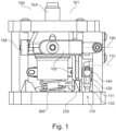
- Fig. 1 illustrates an embodiment of the operating element 100.
- the operating element 100 comprises a lever 101, which includes lever component 102 and further lever components 103 and 104.
- Lever component 102 is pivoted about a first rotational axis 105 when lever 101 is pivoted correspondingly.
- lever 101 may comprise a handle mounted to lever component 103, and the user may pivot the handle and component 103 together with the lever component 102 about rotational axis 105.
- the lever component 102 is shaped as a bracket and forms part of a cardan mount; it rotatably supports the lever against a housing of operating element 100.
- the further component 104 provides a similar rotational support about a orthogonal rotational axis (not indicated) so that the lever may be pivoted in two orthogonal directions.
- a corresponding configuration can be provided for the lever component 104 and thus for the other pivoting direction of the lever 101. It should be clear that a respective cardan suspension can be implemented in many different ways, and that the present solution is applicably to any of these.
- the lever may only be pivotable about a single rotational axis.
- the lever component may in such case be the component 103 (i.e. no bracket 102 may thus be provided).
- the lever may thus only comprise the lever component pivotable about the first rotational axis, and a handle mounted to the lever component.
- the lever component that rotates about the first rotational axis 105 can thus be implemented in many different ways.
- the operating element further comprises a torque application assembly 110 that includes a pivotable element 111 that is pivotable about the second rotational axis 115. As shown, rotational axes 105, 115 are parallel but spatially offset.
- the pivotable element 111 is coupled by means of a coupling assembly 120 to the lever element 102.
- the configuration is such that when lever component 102 rotates by a first angle about first rotational axis 105, the pivotable element 111 rotates by a larger second angle about the second rotational axis 115.
- the torque application assembly 110 thus implements a transmission mechanism that preferably provides a transmission ratio (i.e. ratio between the first and second rotation angles) of at least 1:1.5.
- a first guiding element 133 that provides a guiding surface 130 is provided.
- Pivotable element 111 interacts with guiding surface 130 to generate a torque when lever component 102 is pivoted.
- Pivoting element may for this purpose comprise a contact member 140 that contacts the guiding surface.
- the generated torque is applied via coupling 120 to lever 101, i.e. to component 102 and component 103. The user thus has to overcome the generated torque when moving the lever, or the torque may drive the lever towards a particular position (e.g. default position).
- operating element 100 may comprise a second guiding element 233 providing a second guiding surface 230, which is explained in more detail further below.
- a restoring assembly 300 may be provided that applies a restoring torque to the lever 101. The restoring torque acts on the lever to drive the lever back into a default position, in particular an equilibrium position, which is illustrated in Fig. 1 .
- Fig. 3 which is a perspective view of the operating element 100 of Fig. 1 , the lever 101 is shown in a pivoted position in which the pivotable element 111, in particular its contact member 140, interacts with the guiding surface 130.
- guiding surface 130 (and thus guiding element 133) is split into three sections, wherein a first section 131 of the guiding surface 130 spans a larger range and two shorter further sections 132 are provided. As can be seen, there is a gap between the first section 131 and each of the further sections 132. A different number of sections or a continuous guiding surface may be provided alternatively.
- the coupling assembly 120 comprises a pin 121 provided on the lever component 102 and a slit 122 in the pivotable element in which the pin 121 is engaged.
- a coupling is thus provided that allows relative rotation between pivotable element 111 and lever component 102 about the rotational axis 123 of the pin. Further, by the slit 122 (or elongated hole or recess), a relative movement is allowed.
- Such coupling allows the pivotable element 111 and the lever component 102 to rotate about the different rotational axes 105, 115 while transferring torque between them.
- the pivotable element is supported by a shaft 116 that supports the pivotable element in a housing of the operating element 100 so as to be rotatable about axis 115.
- the distance between the axis 123 of pin 121 of the coupling 120 and the first rotational axis 105 is larger than the distance between the pin axis 123 and the second rotational axis 115 (for all positions of the pin relative to the pivotable component 111), so that a transmission and lever effect is achieved.
- the coupling assembly 120 may of course be implemented in many different ways, the configuration may for example be reversed.
- the pivotable element 111 has two arms 118 extending in opposite directions and perpendicular to a line that connects the second rotational axis 115 and the central axis 123 of the pin.
- Each arm is provided with a contact member 140.
- the contact member 140 may comprise a contact element 142 and a force applying unit 141.
- Force applying unit 141 may be a spring, such as a coil spring, which pushes the contact element 142 into contact with the guiding surface 130. It may be possible to install springs with different spring stiffness on the contact member 140 so that the desired torque acting on the lever 101 may be set.
- the contact element 142 may be a needle roller, a ball or any other suitable element.
- the contact element is supported in an elongated hole in the pivotable element 111, thus allowing movement in a direction parallel to a direction of force application by the force applying unit 141. Accordingly, if the guiding surface 130 is structured to generated different torques, the contact element 142 can move over respective structures while being displaced and increasing (or decreasing) the force that it applies to the guiding surface via the force application unit 141. Consequently, by changing the shape of the guiding surface 130, the applied force and thus the torque acting on pivotable element 111 can be modulated.
- a locked position in particular refers to a position at which the restoring torque is smaller than the torque required to leave the locked position, so that the lever remains in the locked position.
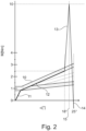
- the lever If the lever is now released by the user, the torque generated by the locking position by means of the first and second guiding surfaces is larger than the restoring torque, so that the lever will stay at the locked position and not move back to the default position. For moving back to the default position, the maximum torque at the intermediate position 15 has to be again overcome by user actuation. If the lever is released by the user thereafter, it will return to the default position by means of the restoring torque applied by restoring assembly 300.
- the torque characteristic looks different when the lever moves away from the default position, wherein the restoring torque is added to the torque generated by assembly 110, and when the lever moves towards the default position, wherein the restoring torque is subtracted from the torque generated by assembly 110.
- the torque that needs to be applied by the user to enter the locked position is thus higher than the torque required to leave the locked position.
- no restoring assembly 300 is provided.
- the guiding surface 130 may be shaped to generate one or more pressure points in the torque characteristic, which correspond to a local or global maximum of the torque, which has to be overcome by the user, but which is smaller than the restoring torque. The user thus obtains haptic feedback when passing such pressure point, but the lever will nevertheless return to its default position when released.
- the guiding surface may have a protrusion that protrudes towards the second rotational axis for generating a pressure point.
- the contact elements 142, 242 may be configured to either slide and/or roll on the guiding surface.
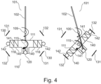
- Fig. 4 schematically illustrates the operation of the torque application assembly 110 of the embodiment of Fig. 1 .
- the pivotable element 111 with its two arms 118 and the respective contact members 140 is shown.
- Each contact member comprises the force applying unit 141 and the contact element 142.
- the left hand side of Fig. 4 shows the default position of the lever 101.
- the guiding surface is sectioned into sections 131, 132 separated by a gap. In the illustrated default position and when the lever is moved (slightly) out of the default position, the contact elements 142 are located within the gap so that no torque is applied to lever component 102 by pivotable element 111.
- FIG. 4 illustrates a situation in which the lever has been moved out of the default position and far enough so that the contact elements 142 engage the sections 132 of the guiding surface 130. Accordingly, the springs 141 are compressed and the pivotable element 111 will apply a torque to lever component 102.
- the guiding surface sections 131, 132 may in the example of Fig. 4 generate a pressure point that needs to be overcome when moving the lever further.
- the pivoting angle of lever component 102 about rotation axis 105 translates into a significantly larger pivoting angle of pivotable element 111 about rotation axis 115.
- the transmission ratio is preferably larger than 1:1.5, preferably larger than 1:1.8 or even larger than 1:2.
- a corresponding torque increase my accordingly be achieved.
- the user needs to apply a significantly higher torque to lever 101 in order to overcome the torque generated by assembly 110 than it would be the case without such transmission.
- the same compressive force of the springs 141 can thus generate a higher torque.
- a larger angular displacement is available for generating the torque characteristic, thus resulting in an increased resolution.
- the sections 131, 132 of the guiding surface 130 may be shaped to create a pressure point, a locked position or any other desirable torque characteristic.
- Fig. 5 shows an embodiment that is a modification of the above-described embodiments. All above explanations are thus equally applicable.
- the guiding surface 130 is continuous over the pivoting range of the lever 101.
- the contact elements 142 are always in contact with the guiding surface 130 over the whole pivoting range. This does naturally not exclude that a separate guiding surface 130 is provided for each contact member 140 of pivotable element 111.
- the shape of the guiding surface 130 of Fig. 5 is such that a restoring torque is generated that acts on the lever when the lever is moved out of the default position shown in the left part of Fig. 5 .
- the default position may be an equilibrium position in which no torque is applied to lever 101, or the applied torques compensate each other (e.g. of the two arms 118).
- the guiding surface is shaped such that the compression of spring 141 is increased if the lever is pivoted in one or the other direction. Accordingly, a torque is applied to pivotable element 111 about the rotation axis 115 which is transferred via the coupling 120 to a torque acting on the lever component about rotational axis 105, with the respective transmission ratio. A relatively high restoring torque may thus be generated in a compact assembly.
- the guiding surface 113 may be shaped cycloidic, or may have another shape, such as circular (with a higher radius of curvature) or parabolic, or it may have linear slopes.
- a cycloidic shape may result in a constant force increase generated by the force applying unit 311 and thus a constant torque increase transferred to the lever 101.
- the guiding surface 130 may be shaped to include further features that may generate a pressure point, a locked position, and/or the like in the torque characteristic.
- the lever is pivoted to a respective position in which the guiding surface 130 transitions into a pressure point feature at which the springs 141 are compressed at a higher rate. An increased torque thus has to be overcome by the user when moving the lever past such pressure point.
- Fig. 6 illustrates in more detail the shape of a guiding surface 130 that may implement a pressure point 135 in any of the embodiments disclosed herein.
- the guiding surface 130 has a flat section at pressure point 135. If the contact element 142 passes the flat section, the force applying unit 141 is further compressed, thus generating a higher force and accordingly a higher torque applied via pivotable element 111 to the lever 101. Consequently, the user obtains haptic feedback that the pressure point is being passed. This may indicate to the user an activation of a particular function or the like.
- Fig. 7 illustrates in more detail the shape of a guiding surface 130 that may implement a locked position 136 in any of the embodiments disclosed herein.
- the surface 130 curves towards the rotation axis 115, resulting in an increasing compression of the force applying unit 141, until the maximum compression (and thus maximum torque) is reached at the intermediate position 15.
- the guiding surface 130 comprises a recess or indent that allows the force applying unit 141 to expand again, thereby reducing the torque applied to the lever. Accordingly, the pivotable element 111 and thus the lever 101 becomes locked in the respective position, since an increase in torque is required to move the lever out of the locked position 136.
- the recess may be shaped such that no restoring torque is applied at the locked position. The restoring torque does therefore not lower the torque required to move the lever out of such locked position 136.
- the guiding surface 130 can be sectioned, thus allowing a great versatility and variety of shapes.
- the torque acting on the lever can be increased in several ways, foremost by the transmission mechanism of the torque application assembly. Further torque increases becomes possible by using one or a combination of providing two contact members on the pivotable element that are in contact with the guiding surface, by the spacing of the contact element(s) from the second rotational axis, and the additional torque provided by the interaction with the second guiding surface. Even in a small and compact operating element, a high torque and useful tactile feedback can thereby be generated.
- the precision of the tactile features in the torque characteristic is further improved by the increase in resolution achieved by the torque application assembly, in particular its transmission mechanism.
Landscapes
- Physics & Mathematics (AREA)
- General Physics & Mathematics (AREA)
- Engineering & Computer Science (AREA)
- Automation & Control Theory (AREA)
- Mechanical Control Devices (AREA)
Priority Applications (2)
| Application Number | Priority Date | Filing Date | Title |
|---|---|---|---|
| EP23217681.8A EP4575704A1 (de) | 2023-12-18 | 2023-12-18 | Bedienelement mit drehmoment-applikationsanordnung |
| PCT/EP2024/085699 WO2025131928A1 (en) | 2023-12-18 | 2024-12-11 | Operating element with torque application assembly |
Applications Claiming Priority (1)
| Application Number | Priority Date | Filing Date | Title |
|---|---|---|---|
| EP23217681.8A EP4575704A1 (de) | 2023-12-18 | 2023-12-18 | Bedienelement mit drehmoment-applikationsanordnung |
Publications (1)
| Publication Number | Publication Date |
|---|---|
| EP4575704A1 true EP4575704A1 (de) | 2025-06-25 |
Family
ID=89223953
Family Applications (1)
| Application Number | Title | Priority Date | Filing Date |
|---|---|---|---|
| EP23217681.8A Pending EP4575704A1 (de) | 2023-12-18 | 2023-12-18 | Bedienelement mit drehmoment-applikationsanordnung |
Country Status (2)
| Country | Link |
|---|---|
| EP (1) | EP4575704A1 (de) |
| WO (1) | WO2025131928A1 (de) |
Citations (4)
| Publication number | Priority date | Publication date | Assignee | Title |
|---|---|---|---|---|
| GB1350073A (en) * | 1970-07-11 | 1974-04-18 | British Leyland Truck & Bus | Gear selector |
| US20110303039A1 (en) * | 2007-08-08 | 2011-12-15 | Kopp John D | Control stick adapted for use in a fly-by-wire flight control system, and linkage for use therein |
| CN104965561A (zh) * | 2014-03-24 | 2015-10-07 | 爱乐宝两合公司 | 具有固有的安全力反馈的操纵杆 |
| EP2883117B1 (de) * | 2012-08-10 | 2019-08-28 | Preh GmbH | Bedienelement mit magnethaptik |
-
2023
- 2023-12-18 EP EP23217681.8A patent/EP4575704A1/de active Pending
-
2024
- 2024-12-11 WO PCT/EP2024/085699 patent/WO2025131928A1/en active Pending
Patent Citations (4)
| Publication number | Priority date | Publication date | Assignee | Title |
|---|---|---|---|---|
| GB1350073A (en) * | 1970-07-11 | 1974-04-18 | British Leyland Truck & Bus | Gear selector |
| US20110303039A1 (en) * | 2007-08-08 | 2011-12-15 | Kopp John D | Control stick adapted for use in a fly-by-wire flight control system, and linkage for use therein |
| EP2883117B1 (de) * | 2012-08-10 | 2019-08-28 | Preh GmbH | Bedienelement mit magnethaptik |
| CN104965561A (zh) * | 2014-03-24 | 2015-10-07 | 爱乐宝两合公司 | 具有固有的安全力反馈的操纵杆 |
Also Published As
| Publication number | Publication date |
|---|---|
| WO2025131928A1 (en) | 2025-06-26 |
Similar Documents
| Publication | Publication Date | Title |
|---|---|---|
| KR101110525B1 (ko) | 스위칭 명령을 기계적 커플링 없이 자동식 자동차 기어박스에 전달하기 위한 스위칭 장치 | |
| US8359945B2 (en) | Adjustable steering column assembly | |
| EP3380385B1 (de) | Einschienenbahnschalter mit schwerkraftgestütztem betätigungsmechanismus | |
| CN104520183A (zh) | 用于控制飞机的操纵杆 | |
| CN111002880A (zh) | 具有俯仰弹簧单元的汽车座椅 | |
| EP4575704A1 (de) | Bedienelement mit drehmoment-applikationsanordnung | |
| US11327519B2 (en) | Control lever with sliding guide | |
| US12210370B2 (en) | Operating lever comprising link system | |
| EP3406483B1 (de) | Ausklappbare fussstütze | |
| EP2225623A1 (de) | Steuerknüppel | |
| EP3635183B1 (de) | Mechanismus zur positionseinstellung einer in baumaschinen integrierten mechanischen steuerkonsole | |
| KR101893243B1 (ko) | 로터 블레이드 제어 장치 | |
| EP2633208B1 (de) | Steuerungsvorrichtung für ein raupenfahrzeug | |
| EP4553608A1 (de) | Bedienelement für eine maschine | |
| EP4553607A1 (de) | Bedienelement für eine maschine | |
| AU4293200A (en) | Adjusting device | |
| EP4579377A1 (de) | Verbindungssystem, betätigungshebel mit verbindungssystem und verfahren zum betrieb | |
| US8225632B2 (en) | Key interlock device for vehicle | |
| EP4579376A1 (de) | Bedieneinheit | |
| JP4711327B2 (ja) | トランスミッションの遠隔操作装置 | |
| JPH08722Y2 (ja) | 電気式ジョイスティック装置 | |
| WO2025140934A1 (en) | Link system, operating lever with link system and method of operating | |
| JP4603651B2 (ja) | 操作レバー装置 | |
| JP4424025B2 (ja) | 操縦装置 | |
| CN119512313A (zh) | 一种双自由度运动机构及操纵装置 |
Legal Events
| Date | Code | Title | Description |
|---|---|---|---|
| PUAI | Public reference made under article 153(3) epc to a published international application that has entered the european phase |
Free format text: ORIGINAL CODE: 0009012 |
|
| STAA | Information on the status of an ep patent application or granted ep patent |
Free format text: STATUS: THE APPLICATION HAS BEEN PUBLISHED |
|
| AK | Designated contracting states |
Kind code of ref document: A1 Designated state(s): AL AT BE BG CH CY CZ DE DK EE ES FI FR GB GR HR HU IE IS IT LI LT LU LV MC ME MK MT NL NO PL PT RO RS SE SI SK SM TR |
|
| STAA | Information on the status of an ep patent application or granted ep patent |
Free format text: STATUS: THE APPLICATION IS DEEMED TO BE WITHDRAWN |