EP4553930A2 - Elektroden-/separatorstapel für eine batteriezelle sowie verfahren zur herstellung eines solchen elektroden-/separatorstapels - Google Patents
Elektroden-/separatorstapel für eine batteriezelle sowie verfahren zur herstellung eines solchen elektroden-/separatorstapels Download PDFInfo
- Publication number
- EP4553930A2 EP4553930A2 EP24201507.1A EP24201507A EP4553930A2 EP 4553930 A2 EP4553930 A2 EP 4553930A2 EP 24201507 A EP24201507 A EP 24201507A EP 4553930 A2 EP4553930 A2 EP 4553930A2
- Authority
- EP
- European Patent Office
- Prior art keywords
- electrode
- separator
- laminated composite
- edge
- protection film
- Prior art date
- Legal status (The legal status is an assumption and is not a legal conclusion. Google has not performed a legal analysis and makes no representation as to the accuracy of the status listed.)
- Pending
Links
Images


Classifications
-
- H—ELECTRICITY
- H01—ELECTRIC ELEMENTS
- H01M—PROCESSES OR MEANS, e.g. BATTERIES, FOR THE DIRECT CONVERSION OF CHEMICAL ENERGY INTO ELECTRICAL ENERGY
- H01M50/00—Constructional details or processes of manufacture of the non-active parts of electrochemical cells other than fuel cells, e.g. hybrid cells
- H01M50/40—Separators; Membranes; Diaphragms; Spacing elements inside cells
- H01M50/471—Spacing elements inside cells other than separators, membranes or diaphragms; Manufacturing processes thereof
- H01M50/474—Spacing elements inside cells other than separators, membranes or diaphragms; Manufacturing processes thereof characterised by their position inside the cells
-
- H—ELECTRICITY
- H01—ELECTRIC ELEMENTS
- H01M—PROCESSES OR MEANS, e.g. BATTERIES, FOR THE DIRECT CONVERSION OF CHEMICAL ENERGY INTO ELECTRICAL ENERGY
- H01M10/00—Secondary cells; Manufacture thereof
- H01M10/42—Methods or arrangements for servicing or maintenance of secondary cells or secondary half-cells
- H01M10/4235—Safety or regulating additives or arrangements in electrodes, separators or electrolyte
-
- H—ELECTRICITY
- H01—ELECTRIC ELEMENTS
- H01M—PROCESSES OR MEANS, e.g. BATTERIES, FOR THE DIRECT CONVERSION OF CHEMICAL ENERGY INTO ELECTRICAL ENERGY
- H01M10/00—Secondary cells; Manufacture thereof
- H01M10/04—Construction or manufacture in general
-
- H—ELECTRICITY
- H01—ELECTRIC ELEMENTS
- H01M—PROCESSES OR MEANS, e.g. BATTERIES, FOR THE DIRECT CONVERSION OF CHEMICAL ENERGY INTO ELECTRICAL ENERGY
- H01M10/00—Secondary cells; Manufacture thereof
- H01M10/04—Construction or manufacture in general
- H01M10/0413—Large-sized flat cells or batteries for motive or stationary systems with plate-like electrodes
-
- H—ELECTRICITY
- H01—ELECTRIC ELEMENTS
- H01M—PROCESSES OR MEANS, e.g. BATTERIES, FOR THE DIRECT CONVERSION OF CHEMICAL ENERGY INTO ELECTRICAL ENERGY
- H01M10/00—Secondary cells; Manufacture thereof
- H01M10/04—Construction or manufacture in general
- H01M10/0436—Small-sized flat cells or batteries for portable equipment
-
- H—ELECTRICITY
- H01—ELECTRIC ELEMENTS
- H01M—PROCESSES OR MEANS, e.g. BATTERIES, FOR THE DIRECT CONVERSION OF CHEMICAL ENERGY INTO ELECTRICAL ENERGY
- H01M10/00—Secondary cells; Manufacture thereof
- H01M10/05—Accumulators with non-aqueous electrolyte
- H01M10/052—Li-accumulators
-
- H—ELECTRICITY
- H01—ELECTRIC ELEMENTS
- H01M—PROCESSES OR MEANS, e.g. BATTERIES, FOR THE DIRECT CONVERSION OF CHEMICAL ENERGY INTO ELECTRICAL ENERGY
- H01M10/00—Secondary cells; Manufacture thereof
- H01M10/05—Accumulators with non-aqueous electrolyte
- H01M10/058—Construction or manufacture
- H01M10/0585—Construction or manufacture of accumulators having only flat construction elements, i.e. flat positive electrodes, flat negative electrodes and flat separators
-
- H—ELECTRICITY
- H01—ELECTRIC ELEMENTS
- H01M—PROCESSES OR MEANS, e.g. BATTERIES, FOR THE DIRECT CONVERSION OF CHEMICAL ENERGY INTO ELECTRICAL ENERGY
- H01M4/00—Electrodes
- H01M4/02—Electrodes composed of, or comprising, active material
- H01M4/62—Selection of inactive substances as ingredients for active masses, e.g. binders, fillers
- H01M4/621—Binders
- H01M4/622—Binders being polymers
- H01M4/623—Binders being polymers fluorinated polymers
-
- H—ELECTRICITY
- H01—ELECTRIC ELEMENTS
- H01M—PROCESSES OR MEANS, e.g. BATTERIES, FOR THE DIRECT CONVERSION OF CHEMICAL ENERGY INTO ELECTRICAL ENERGY
- H01M4/00—Electrodes
- H01M4/02—Electrodes composed of, or comprising, active material
- H01M4/64—Carriers or collectors
- H01M4/66—Selection of materials
- H01M4/665—Composites
- H01M4/667—Composites in the form of layers, e.g. coatings
-
- H—ELECTRICITY
- H01—ELECTRIC ELEMENTS
- H01M—PROCESSES OR MEANS, e.g. BATTERIES, FOR THE DIRECT CONVERSION OF CHEMICAL ENERGY INTO ELECTRICAL ENERGY
- H01M4/00—Electrodes
- H01M4/02—Electrodes composed of, or comprising, active material
- H01M4/64—Carriers or collectors
- H01M4/70—Carriers or collectors characterised by shape or form
-
- H—ELECTRICITY
- H01—ELECTRIC ELEMENTS
- H01M—PROCESSES OR MEANS, e.g. BATTERIES, FOR THE DIRECT CONVERSION OF CHEMICAL ENERGY INTO ELECTRICAL ENERGY
- H01M50/00—Constructional details or processes of manufacture of the non-active parts of electrochemical cells other than fuel cells, e.g. hybrid cells
- H01M50/40—Separators; Membranes; Diaphragms; Spacing elements inside cells
- H01M50/46—Separators, membranes or diaphragms characterised by their combination with electrodes
-
- H—ELECTRICITY
- H01—ELECTRIC ELEMENTS
- H01M—PROCESSES OR MEANS, e.g. BATTERIES, FOR THE DIRECT CONVERSION OF CHEMICAL ENERGY INTO ELECTRICAL ENERGY
- H01M50/00—Constructional details or processes of manufacture of the non-active parts of electrochemical cells other than fuel cells, e.g. hybrid cells
- H01M50/40—Separators; Membranes; Diaphragms; Spacing elements inside cells
- H01M50/46—Separators, membranes or diaphragms characterised by their combination with electrodes
- H01M50/461—Separators, membranes or diaphragms characterised by their combination with electrodes with adhesive layers between electrodes and separators
-
- H—ELECTRICITY
- H01—ELECTRIC ELEMENTS
- H01M—PROCESSES OR MEANS, e.g. BATTERIES, FOR THE DIRECT CONVERSION OF CHEMICAL ENERGY INTO ELECTRICAL ENERGY
- H01M50/00—Constructional details or processes of manufacture of the non-active parts of electrochemical cells other than fuel cells, e.g. hybrid cells
- H01M50/40—Separators; Membranes; Diaphragms; Spacing elements inside cells
- H01M50/471—Spacing elements inside cells other than separators, membranes or diaphragms; Manufacturing processes thereof
- H01M50/477—Spacing elements inside cells other than separators, membranes or diaphragms; Manufacturing processes thereof characterised by their shape
-
- H—ELECTRICITY
- H01—ELECTRIC ELEMENTS
- H01M—PROCESSES OR MEANS, e.g. BATTERIES, FOR THE DIRECT CONVERSION OF CHEMICAL ENERGY INTO ELECTRICAL ENERGY
- H01M50/00—Constructional details or processes of manufacture of the non-active parts of electrochemical cells other than fuel cells, e.g. hybrid cells
- H01M50/40—Separators; Membranes; Diaphragms; Spacing elements inside cells
- H01M50/471—Spacing elements inside cells other than separators, membranes or diaphragms; Manufacturing processes thereof
- H01M50/48—Spacing elements inside cells other than separators, membranes or diaphragms; Manufacturing processes thereof characterised by the material
- H01M50/486—Organic material
-
- H—ELECTRICITY
- H01—ELECTRIC ELEMENTS
- H01M—PROCESSES OR MEANS, e.g. BATTERIES, FOR THE DIRECT CONVERSION OF CHEMICAL ENERGY INTO ELECTRICAL ENERGY
- H01M10/00—Secondary cells; Manufacture thereof
- H01M10/04—Construction or manufacture in general
- H01M10/0404—Machines for assembling batteries
-
- Y—GENERAL TAGGING OF NEW TECHNOLOGICAL DEVELOPMENTS; GENERAL TAGGING OF CROSS-SECTIONAL TECHNOLOGIES SPANNING OVER SEVERAL SECTIONS OF THE IPC; TECHNICAL SUBJECTS COVERED BY FORMER USPC CROSS-REFERENCE ART COLLECTIONS [XRACs] AND DIGESTS
- Y02—TECHNOLOGIES OR APPLICATIONS FOR MITIGATION OR ADAPTATION AGAINST CLIMATE CHANGE
- Y02E—REDUCTION OF GREENHOUSE GAS [GHG] EMISSIONS, RELATED TO ENERGY GENERATION, TRANSMISSION OR DISTRIBUTION
- Y02E60/00—Enabling technologies; Technologies with a potential or indirect contribution to GHG emissions mitigation
- Y02E60/10—Energy storage using batteries
-
- Y—GENERAL TAGGING OF NEW TECHNOLOGICAL DEVELOPMENTS; GENERAL TAGGING OF CROSS-SECTIONAL TECHNOLOGIES SPANNING OVER SEVERAL SECTIONS OF THE IPC; TECHNICAL SUBJECTS COVERED BY FORMER USPC CROSS-REFERENCE ART COLLECTIONS [XRACs] AND DIGESTS
- Y02—TECHNOLOGIES OR APPLICATIONS FOR MITIGATION OR ADAPTATION AGAINST CLIMATE CHANGE
- Y02P—CLIMATE CHANGE MITIGATION TECHNOLOGIES IN THE PRODUCTION OR PROCESSING OF GOODS
- Y02P70/00—Climate change mitigation technologies in the production process for final industrial or consumer products
- Y02P70/50—Manufacturing or production processes characterised by the final manufactured product
Definitions
- the invention relates to an electrode/separator stack for a battery cell according to the preamble of claim 1 and to a method for producing such an electrode/separator stack according to the preamble of claim 10.
- Such an electrode/separator stack can be manufactured by single-sheet stacking.
- single-sheet stacking the placement accuracy of the electrode and separator sheets in the electrode/separator stack is of great importance for the safety and performance of the battery cell.
- the electrochemical performance of the battery cell decreases more quickly with less electrode coverage during operation.
- incorrect sheet placement can lead to direct contact between the anode and cathode, which can trigger a short circuit and battery cell failure.
- the anode in the electrode/separator stack can, for example, be larger all around (e.g., 1.5 mm) than the cathode, and the separator can be larger than the anode by an allowance (e.g., 1.5 mm).
- the aforementioned single-sheet stacking is carried out using complex handling equipment. These receive their coordinates based on image processing, in which the position of each deposited electrode/separator sheet is optically recorded and evaluated after each sheet deposit to determine the depositing accuracy.
- a battery cell which has an inner element having a first main surface, a second main surface, a first side surface, a second side surface, a first end surface, and a second end surface. Furthermore, a first inner electrode extending to the first end surface, a second electrode extending to the second end surface, a separator layer arranged between the first and second electrodes, and an electrolytic solution are provided. Furthermore, the first electrode is arranged on the first end surface and the second electrode is arranged on the second end surface. The first electrode, the second electrode, and the separator layer are joined together to form a one-piece composite.
- An electrode stack is known that is provided with an electrically insulating coating on at least one sheet edge. This coating is applied from the liquid phase and extends over the entire height of the electrode stack.
- JP 5375263 B2 A manufacturing method and apparatus for a high-performance battery is known in which a plurality of laminates consisting of an electrode and a separator are formed.
- the object of the invention is to provide an electrode/separator stack and a method for producing such an electrode/separator stack, in which the stacking process can be carried out in a simpler manufacturing process and with greater deposition accuracy compared to the prior art.
- the invention is based on an electrode/separator stack for a battery cell, which is composed of at least one electrode, in particular a cathode, and a counter electrode, in particular anode.
- the electrode is a component of a laminated composite in which a separator is laminated to each side of the electrode.
- the two separators project beyond the electrode at the edge with a projection.
- an edge gap between the two separator projections is preferably completely filled with an edge protection film.
- the edge protection film can have the same material thickness as the electrode, viewed in the thickness direction of the laminated composite. In this way, the corners and edges of the electrode are protected from external mechanical stresses by means of the edge protection film.
- the edge protection film can be is carried out, provide a dimensionally stable contact surface that enables damage-free transverse displacement of the electrode in the electrode/separator stack. Furthermore, the edge protection film acts as electrical insulation, which helps increase the electrical safety of the battery cell.
- the electrode/separator stack according to the invention can be manufactured in the manner of a single-sheet stacking, in which the laminated composite and the counter electrode are stacked on top of each other as individual sheets.
- each of the separators can have an adhesion layer, which allows the separators to be laminated to the electrode in a lamination process, forming the laminated composite.
- the two separators and the intermediate electrode are already joined together to form a single unit before the stacking process, thereby increasing the stacking accuracy in the electrode/separator stack compared to an electrode/separator stack in which the electrodes are stacked as individual sheets.
- the electrode and/or the counter electrode are constructed from a substrate film. This is coated on one or both sides with an electrode active material.
- the active material comprises a binder, in particular a polymer binder, preferably PVDF.
- a binder in particular a polymer binder, preferably PVDF.
- both the active material binder and the edge protection film, and, if applicable, also the adhesion layer are made of the same material. This means that both the adhesion layer and the edge protection film have the same material structure as the active material binder. This ensures the resistance of the edge protection film to the electrolyte. Furthermore, it is guaranteed that the material pairing between the edge protection film and the active material binder is electrochemically stable or resistant.
- the laminated composite consisting of the two separators and the intermediate electrode, can be provided as a rectangular, flat blank.
- the substrate film of the electrode can be extended laterally outwards beyond the separator edges with a conductor tab.
- the edge-side gap filled with the edge protection film can run continuously at least along the blank side facing away from the conductor tab side and along the two blank sides of the laminated composite that are perpendicular to the conductor tab side.
- No edge protection film is provided on the conductor tab side itself so that the conductor tab from This prevents thickening (caused by the edge protection film) at the level of the conductor lug, which would then become noticeable later. It is therefore advantageous if the edge protection film is only present on three of the four sides of the cut to prevent any thickening.
- the counterelectrode can preferably be dimensioned larger than the electrode by a certain amount, for example, 1 to 3 mm.
- the counterelectrode and the separators can preferably be manufactured as congruent sheet blanks. This means that the counterelectrode—with the exception of its conductor lug—has the same area and contour as the separator, so that the corners and edges of the counterelectrode can be aligned in the stacking direction with the corners and edges of the separators.
- a method for manufacturing the electrode/separator stack can be divided into a stacking process and a subsequent alignment process.
- the laminated composite consisting of separators and electrode, as well as the counterelectrode, are stacked one on top of the other in the manner of a single-sheet stack.
- the laminated composite and the counterelectrode can be aligned in the stacking direction. Due to the provision of the edge protection film according to the invention, the laminated composite is dimensionally stable, whereby a damage-free position correction of the laminated composite transverse to the stacking direction can be carried out.
- Such a dimensionally stable laminated composite also offers the adjacent counterelectrode a stable counterhold or support base, whereby a position correction of the counterelectrode can be carried out without damage.
- at least one transverse stop in particular a slide, can be used in the alignment process.
- the cross stop can be used to correct the position of a stack component that is offset transversely to the stacking direction, i.e. the laminated composite or the counter electrode, i.e. to align it in alignment with the other stack components.
- the edge protection film can be applied to the laminated composite in any suitable manner.
- the edge protection film can be applied to the laminated composite in a coating process in which a viscous starting component of the edge protection film is applied directly into the edge gap of the laminated composite.
- the edge protection film can also be applied as separate component, i.e. as a solid phase material (e.g. foil, adhesive film).
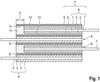
- FIG. 1 A finished electrode/separator stack for a battery cell is shown. This comprises, in the stacking direction, an anode A, a cathode K, and another anode A and a cathode K, each with separators S arranged between them.
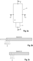
- the anode A is in the Figures 2a to 2c Each is indicated individually. Accordingly, the anode A is a rectangular sheet consisting of a substrate foil 1. This is coated on both sides with active material 3. The substrate foil 1 is extended outward on one rectangular side by an anode conductor lug 5.
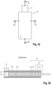
- the cathode K is according to the Figures 3a to 3c also a rectangular sheet blank, which is constructed from a substrate foil 1 coated on both sides with active material 3.
- the substrate foil 1 of the cathode K is extended on one rectangular side with a cathode conductor lug 7.
- the cathode K is according to the Figures 3a to 3c Before performing a stacking process, the cathode K is not provided as a single sheet. Rather, the cathode K, together with the separators S, is part of a laminated composite V, in which the separators S are laminated to the cathode K on both sides under pressure and heat.
- the anode A is dimensioned larger than the cathode K by a circumferential allowance a of, for example, 1 to 3 mm. This allows an overlap of the anode A and the cathode K despite deposition inaccuracies.
- the separators S and the anode A are realized as congruent sheet blanks; this means that the separators S and the anode A have the same area and the same contour with the exception of the anode conductor lug 5, so that in the electrode/separator stack ( Figure 1 ) the corners and edges of the anodes A are aligned in the stacking direction with the corners and edges of the separators S.
- the two separators S project beyond the cathode K by a projection identical to the allowance a. This creates an edge gap 9 that is delimited by the separator projections a and the cathode K.
- the edge gap 9 is completely filled with an edge protection film 11. This has the same material thickness as the cathode K, viewed in the thickness direction of the laminated composite V.
- the two separators S are each formed with an adhesion layer 13, with the aid of which the separators S are laminated to the cathode K in a lamination process under pressure and heat, resulting in the laminated composite V.
- the edge protection film 11 provides mechanical protection for the corners and edges of the laminated composite V. Furthermore, the edge protection film 11 acts as an electrical insulator, preventing direct contact between the anode A and the cathode K. Furthermore, the edge protection film 11 increases the dimensional stability of the laminated composite V at its corners and edges.
- the edge protection film 11 is made of a polymer material. To avoid an unfavorable material pairing between the active material binder, i.e., PVDF, and the edge protection film 11, the edge protection film 11 is also made of PVDF. This also ensures chemical resistance to the electrolyte in the battery cell. It should be emphasized that the invention is not limited to an edge protection film 11 made of PVDF; rather, the edge protection film 11 can also be made of other suitable materials instead of PVDF.
- the electrode/separator stack ( Figure 1 ) is carried out in a stacking process and a subsequent alignment process ( Figures 4 and 5 ).
- the stacking process the laminated composite V and the anode A are stacked alternately on top of each other.
- the alignment process ( Figures 4 and 5 ) a position correction, in which the stack components, i.e. the laminated composite V and the anode A, can be aligned with the other stack components using a slider 15.
- the alignment can also be achieved via gravity and thus be self-centering.
- the alignment function can also be accomplished using a vibrating plate with fixed stops.
- the alignment force F acting on the electrode/separator stack transversely to the stacking direction by means of the slider 15 can, if necessary, also be applied under the effect of gravity.
- stacking accuracy can be achieved independently of image processing and handling devices.
- Stacking accuracy is raised to a high level using cost-effective technology (i.e., slider 15).
- stacking accuracy can be adjusted after the stacking process, i.e., during the alignment process.
Landscapes
- Chemical & Material Sciences (AREA)
- Chemical Kinetics & Catalysis (AREA)
- Electrochemistry (AREA)
- General Chemical & Material Sciences (AREA)
- Engineering & Computer Science (AREA)
- Manufacturing & Machinery (AREA)
- Composite Materials (AREA)
- Materials Engineering (AREA)
- Secondary Cells (AREA)
- Cell Separators (AREA)
- Connection Of Batteries Or Terminals (AREA)
- Battery Electrode And Active Subsutance (AREA)
Abstract
Description
- Die Erfindung betrifft einen Elektroden-/Separatorstapel für eine Batteriezelle nach dem Oberbegriff des Anspruches 1 sowie ein Verfahren zur Fertigung eines solchen Elektroden-/Separatorstapels gemäß dem Oberbegriff des Anspruches 10.
- Die Herstellung eines solchen Elektroden-/Separatorstapels kann durch Einzelblattstapeln erfolgen. Beim Einzelblattstapeln ist die Ablagegenauigkeit der Elektroden- und Separatorblätter im Elektroden-/Separatorstapel von großer Bedeutung für die Sicherheit und Leistungsfähigkeit der Batteriezelle. So nimmt die elektrochemische Leistungsfähigkeit der Batteriezelle mit geringerer Elektroden-Überdeckung im Betrieb schneller ab. Zudem kann eine fehlerhafte Blatt-Ablage zu einem direkten Kontakt der Anode und Kathode führen, wodurch ein Kurzschluss sowie ein Batteriezellen-Ausfall auslösbar ist. Um eine vollständige Überdeckung der Anode und Kathode trotz Ablageungenauigkeiten zu verbessern, kann beispielhaft die Anode im Elektroden-/Separatorstapel umlaufend um ein Aufmaß (zum Beispiel 1,5 mm) größer sein als die Kathode sowie der Separator ein Aufmaß größer sein als die Anode.
- Das oben erwähnte Einzelblattstapeln wird fertigungstechnisch aufwendig mittels Handhabungseinrichtungen durchgeführt. Diese erhalten ihre Koordinaten auf Basis einer Bildverarbeitung, bei der nach jeder Blatt-Ablage die Position jedes abgelegten Elektroden-/Separator-Blattes optisch erfasst und ausgewertet wird, um die Ablagegenauigkeit zu bestimmen.
- Bei einer solchen optischen Erfassung der Ablagegenauigkeit ist eine nach dem Stapelprozess erfolgende Positionskorrektur der bereits abgelegten Elektroden-/Separatorblätter nicht vorgesehen, so dass der Ablagefehler zwar erkannt wird, jedoch nachträglich nicht mehr beseitigt werden kann. Zudem ist die mithilfe von Bildverarbeitung durchgeführte Stapelfertigung messtechnisch aufwändig und kann systembedingt zu Positionsabweichungen der im Elektroden-/Separatorstapel gestapelten Einzelblätter führen.
- Aus der
US 2022/0148821 A1 ist eine Batteriezelle bekannt, die ein inneres Element aufweist, das eine erste Hauptoberfläche, eine zweite Hauptoberfläche, eine erste Seitenfläche, eine zweite Seitenfläche, eine erste Endfläche und eine zweite Endfläche aufweist. Ferner ist eine erste innere Elektrode, die sich bis zur ersten Endfläche erstreckt, eine zweite Elektrode, die sich bis zur zweiten Endfläche erstreckt, eine Separatorschicht, die zwischen der ersten und der zweiten Elektrode angeordnet ist, und eine elektrolytische Lösung bereitgestellt. Außerdem ist die erste Elektrode an der ersten Endfläche und die zweite Elektrode an der zweiten Endfläche angeordnet. Die erste Elektrode, die zweite Elektrode und die Separatorschicht sind zu einem einstückigen Verbund zusammengefügt. - Aus
DE 10 2016 217 397 A1 ist ein Elektrodenstapel bekannt, der an wenigstens einer Blattkantenseite mit einer elektrisch isolierenden Beschichtung versehen ist. Diese wird aus der flüssigen Phase beschichtet und erstreckt sich über die gesamte Höhe des Elektrodenstapels. - Aus der
JP 5375263 B2 - Die Aufgabe der Erfindung besteht darin, einen Elektroden-/Separatorstapel sowie ein Verfahren zur Herstellung eines solchen Elektroden-/Separatorstapels bereitzustellen, bei dem der Stapelvorgang im Vergleich zum Stand der Technik fertigungstechnisch einfacher sowie mit größerer Ablagegenauigkeit durchführbar ist.
- Die Aufgabe ist durch die Merkmale des Anspruches 1 oder 10 gelöst. Bevorzugte Weiterbildungen der Erfindung sind in den Unteransprüchen offenbart.
- Die Erfindung geht von einem Elektroden-/Separatorstapel für eine Batteriezelle aus, der zumindest aus einer Elektrode, insbesondere Kathode, und einer Gegenelektrode, insbesondere Anode, aufgebaut ist. Die Elektrode ist Bestandteil eines laminierten Verbunds, bei dem beidseitig auf die Elektrode jeweils ein Separator laminiert ist. Die beiden Separatoren überragen die Elektrode randseitig mit einem Überstand. Gemäß dem kennzeichnenden Teil des Anspruches 1 ist ein randseitiger Spalt zwischen den beiden Separator-Überständen mit einem Kantenschutzfilm bevorzugt vollständig gefüllt. Der Kantenschutzfilm kann in der Dickenrichtung des laminierten Verbunds betrachtet dieselbe Materialstärke aufweisen wie die Elektrode. Auf diese Weise sind die Ecken und Kanten der Elektrode mithilfe des Kantenschutzfilms vor äußeren mechanischen Belastungen geschützt. Der Kantenschutzfilm kann während eines Ausrichtprozesses, der am fertiggestellten Elektroden-/Separatorstapel durchgeführt wird, eine formstabile Anschlagfläche bereitstellen, mittels der eine beschädigungsfreie Querverlagerung der Elektrode im Elektroden-/Separatorstapel ermöglicht ist. Zudem wirkt der Kantenschutzfilm als eine elektrische Isolierung, mit deren Hilfe die elektrische Sicherheit der Batteriezelle erhöht ist.
- Der erfindungsgemäße Elektroden-/Separatorstapel kann nach Art eines Einzelblattstapelns hergestellt werden, bei dem der laminierte Verbund sowie die Gegenelektrode als Einzelblätter übereinander gestapelt werden.
- In einer technischen Umsetzungen kann jeder der Separatoren eine Adhäsionsschicht aufweisen, mittels der die Separatoren in einem Laminierprozess auf die Elektrode laminierbar sind, und zwar unter Bildung des laminierten Verbunds. Auf diese Weise sind die beiden Separatoren sowie die zwischengeordnete Elektrode bereits vor Durchführung des Stapelprozesses zu einer einstückigen Baueinheit zusammengefügt, wodurch die Stapelgenauigkeit im Elektroden-/Separatorstapel erhöht ist, und zwar im Vergleich zu einem Elektroden-/Separatorstapel, bei dem die Elektroden als Einzelblätter gestapelt werden.
- Die Elektrode und/oder die Gegenelektrode sind aus einer Substratfolie aufgebaut. Diese ist ein- oder beidseitig mit einem Elektroden-Aktivmaterial beschichtet. Das Aktivmaterial weist einen Binder, insbesondere einen Polymer-Binder, nämlich bevorzugt PVDF, auf. Um eine ungünstige Materialpaarung zwischen dem Aktivmaterial und dem Kantenschutzfilm sowie gegebenenfalls der Adhäsionsschicht zu vermeiden, ist sowohl der Aktivmaterial-Binder als auch der Kantenschutzfilm und gegebenenfalls auch die Adhäsionsschicht materialgleich ausgebildet. Das heißt, dass sowohl die Adhäsionsschicht als auch der Kantenschutzfilm den gleichen Materialaufbau aufweisen wie der Aktivmaterial-Binder. Dadurch ist eine Beständigkeit des Kantenschutzfilms gegenüber dem Elektrolyt gewährleistet. Zudem ist gewährleistet, dass die Materialpaarung zwischen Kantenschutzfilm und Aktivmaterial-Binder elektrochemisch stabil beziehungsweise beständig ist.
- Der laminierte Verbund, bestehend aus den beiden Separatoren sowie der zwischengeordneten Elektrode, kann als ein rechteckförmiger flächiger Zuschnitt bereitgestellt sein. An dessen einer Zuschnitt-Seite (nachfolgend "Ableiterfahnen-Seite") kann die Substratfolie der Elektrode mit einer Ableiterfahne seitlich nach außen über die Separator-Ränder hinaus verlängert sein. Der mit dem Kantenschutzfilm gefüllte randseitige Spalt kann zumindest entlang der von der Ableiterfahnen-Seite abgewandten Zuschnitt-Seite sowie entlang der beiden zur Ableiterfahnen-Seite rechtwinkligen Zuschnitt-Seiten des laminierten Verbunds durchgängig verlaufen. An der Ableiterfahnen-Seite selbst ist kein Kantenschutzfilm bereitgestellt, damit die Ableiterfahne aus dem Verbund herausführbar ist. Auf diese Weise wird eine Aufdickung (bedingt durch den Kantenschutzfilm) in Höhe der Ableiterfahne vermieden, die sich dann später bemerkt machen würde. Es ist daher vorteilhaft, wenn der Kantenschutzfilm nur an drei der insgesamt vier Zuschnitt-Seiten vorhanden ist, damit keine Verdickung auftreten kann.
- Um eine vollständige Überdeckung der Elektrode (das heißt Kathode) und der Gegenelektrode (das heißt Anode) trotz Ablageungenauigkeiten zu ermöglichen, kann bevorzugt die Gegenelektrode umlaufend um ein Aufmaß, zum Beispiel um 1 bis 3 mm größer dimensioniert sein als die Elektrode. Bevorzugt können die Gegenelektrode und die Separatoren als deckungsgleiche Blatt-Zuschnitte gefertigt sein. Das heißt, dass die Gegenelektrode - mit Ausnahme ihrer Ableiterfahne - flächengleich sowie konturgleich wie der Separator dimensioniert ist, so dass die Ecken und Kanten der Gegenelektrode in Stapelrichtung in Flucht mit den Ecken und Kanten der Separatoren ausrichtbar sind.
- Ein Verfahren zur Fertigung des Elektroden-/Separatorstapels ist in einen Stapelprozess und in einen nachfolgenden Ausrichtprozess unterteilbar. Im Stapelprozess wird der laminierte Verbund, bestehend aus Separatoren und Elektrode, sowie die Gegenelektrode nach Art einer Einzelblattstapelung übereinander gestapelt. Im nachfolgenden Ausrichtprozess sind der laminierte Verbund sowie die Gegenelektrode in Stapelrichtung in Flucht zueinander ausrichtbar. Aufgrund der Bereitstellung des erfindungsgemäßen Kantenschutzfilms ist der laminierte Verbund formstabil gestaltet, wodurch eine beschädigungsfreie Positionskorrektur des laminierten Verbunds quer zur Stapelrichtung durchführbar ist. Ein derart formstabiler laminierter Verbund bietet auch der benachbarten Gegenelektrode einen stabilen Gegenhalt beziehungswiese eine stabile Abstützbasis, wodurch eine Positionskorrektur der Gegenelektrode beschädigungsfrei durchführbar ist. Bevorzugt kann im Ausrichtprozess zumindest ein Queranschlag, insbesondere Schieber, zum Einsatz kommen. Mit dem Queranschlag kann eine Positionskorrektur eines quer zur Stapelrichtung lageversetzten Stapelbestandteils, das heißt der laminierte Verbund oder die Gegenelektrode durchgeführt werden, das heißt eine Ausrichtung in Flucht mit den anderen Stapelbestandteilen.
- Der Kantenschutzfilm kann in beliebig geeigneter Weise auf den laminierten Verbund aufgebracht werden. Beispielhaft kann der Kantenschutzfilm in einem Beschichtungsprozess auf den laminierten Verbund aufgebracht werden, bei dem eine viskose Ausgangskomponente des Kantenschutzfilms direkt in den randseitigen Spalt des laminierten Verbunds appliziert wird. In einer demgegenüber vorteilhaften alternativen Variante kann der Kantenschutzfilm auch als separate Komponente eingebracht werden, das heißt als ein Material fester Phase (zum Beispiel Folie, Klebefilm...).
- Nachfolgend ist ein Ausführungsbeispiel der Erfindung anhand der beigefügten Figuren beschrieben.
- Es zeigen:
- Figuren 1 bis 5
- jeweils unterschiedliche Ansichten, anhand derer der Aufbau sowie die Herstellung eines erfindungsgemäßen Elektroden-/Separatorstapels veranschaulicht sind.
- In der
Figur 1 ist ein fertiggestellter Elektroden-/Separatorstapel für eine Batteriezelle gezeigt. Dieser weist in Stapelrichtung in einer Reihenfolge von unten nach oben eine Anode A, eine Kathode K sowie eine weitere Anode A und eine Kathode K mit jeweils zwischengeordneten Separatoren S auf. Die Anode A ist in denFiguren 2a bis 2c jeweils in Alleinstellung angedeutet. Demnach ist die Anode A ein rechteckförmiger Blattzuschnitt, der aus einer Substratfolie 1 aufgebaut ist. Diese ist beidseitig mit Aktivmaterial 3 beschichtet. Die Substratfolie 1 ist an einer Rechteck-Seite nach außen mit einer Anoden-Ableiterfahne 5 verlängert. - Die Kathode K ist gemäß den
Figuren 3a bis 3c ebenfalls ein rechteckförmiger Blattzuschnitt, der aus einer Substratfolie 1 aufgebaut ist, die beidseitig mit Aktivmaterial 3 beschichtet ist. Die Substratfolie 1 der Kathode K ist an einer Rechteck-Seite mit einer Kathoden-Ableiterfahne 7 verlängert. Im Unterschied zur Anode A ist die Kathode K gemäß denFiguren 3a bis 3c vor Durchführung eines Stapelprozesses nicht als ein Einzelblatt bereitgestellt. Vielmehr ist die Kathode K zusammen mit den Separatoren S Bestandteil eines laminierten Verbunds V, bei dem Separatoren S jeweils beidseitig unter Druck und Wärme auf die Kathode K laminiert worden sind. - Im fertiggestellten Elektroden-/Separatorstapel (
Figur 1 ) ragen sämtliche Anoden-Albeiterfahnen 5 von der linken Stapelseite ab, während sämtliche Kathoden-Ableiterfahnen 7 von der rechten Stapelseite abragen. - Wie aus der
Figur 1 weiter hervorgeht, ist die Anode A um ein umlaufenden Aufmaß a von zum Beispiel 1 bis 3 mm größer dimensioniert als die Kathode K. Dadurch kann eine Überdeckung der Anode A und der Kathode K trotz Ablageungenauigkeiten gewährleistet werden. Zudem sind die Separatoren S und die Anode A als deckungsgleiche Blatt-Zuschnitte realisiert; das heißt die Separatoren S und die Anode A sind flächengleich sowie konturgleich mit Ausnahme der Anoden-Ableiterfahne 5, so dass im Elektroden-/Separatorstapel (Figur 1 ) die Ecken und die Kanten der Anoden A in Stapelrichtung in Flucht mit den Ecken und Kanten der Separatoren S ausgerichtet sind. - Im laminierten Verbund V überragen die beiden Separatoren S die Kathode K mit einem Überstand, der identisch mit dem Aufmaß a ist. Auf diese Weise bildet sich ein randseitiger Spalt 9, der von den Separator-Überständen a und der Kathode K begrenzt ist. Der randseitige Spalt 9 ist vollständig mit einem Kantenschutzfilm 11 gefüllt. Dieser weist, in der Dickenrichtung des laminierten Verbunds V betrachtet, dieselbe Materialstärke auf wie die Kathode K. Die beiden Separatoren S sind jeweils mit einer Adhäsionsschicht 13 ausgebildet, mit deren Hilfe die Separatoren S in einem Laminierprozess unter Druck und Wärme auf die Kathode K laminiert werden, wodurch sich der laminierte Verbund V ergibt.
- Der Kantenschutzfilm 11 bildet einen mechanischen Schutz der Ecken und Kanten des laminierten Verbunds V. Zudem wirkt der Kantenschutz 11 als eine elektrische Isolierung, die einen direkten Kontakt zwischen Anode A und Kathode K verhindert. Ferner steigert der Kantenschutzfilm 11 die Formstabilität des laminierten Verbunds V an dessen Ecken und Kanten.
- Der Kantenschutzfilm 11 ist aus einem Polymermaterial gefertigt. Um eine ungünstige Materialpaarung zwischen dem Aktivmaterial-Binder, das heißt PVDF, und dem Kantenschutzfilm 11 zu vermeiden, ist auch der Kantenschutzfilm 11 aus PVDF gefertigt. Dies gewährleistet zudem eine chemische Beständigkeit gegenüber dem Elektrolyt in der Batteriezelle. Es ist hervorzuheben, dass die Erfindung nicht auf einen Kantenschutzfilm 11 aus PVDF beschränkt ist; vielmehr ist der Kantenschutzfilm 11 anstelle von PVDF auch aus anderen geeigneten Materialen herstellbar.
- Der Elektroden-/Separatorstapel (
Figur 1 ) wird in einem Stapelprozess sowie einem nachfolgenden Ausrichtprozess (Figuren 4 und5 ) hergestellt. Im Stapelprozess wird der laminierte Verbund V und die Anode A wechselseitig übereinander gestapelt. Anschließend erfolgt im Ausrichtprozess (Figuren 4 und5 ) eine Positionskorrektur, bei der die Stapelbestandteile, das heißt der laminierte Verbund V und die Anode A, mithilfe eines Schiebers 15 in Flucht mit den anderen Stapelbestandteilen ausrichtbar sind. Es ist hervorzuheben, dass die Erfindung nicht auf die Verwendung des in den Figuren gezeigten Schiebers 15 beschränkt ist. Vielmehr kann die Ausrichtung auch über die Schwerkraft erfolgen und damit selbstzentrierend ausgeführt werden. Alternativ dazu kann die Ausrichtfunktion auch mittels einer Vibrationsplatte mit festen Anschlägen bewerkstelligt werden. - Die mithilfe des Schiebers 15 quer zur Stapelrichtung auf den Elektroden-/Separatorstapel wirkende Ausricht-Kraft F kann gegebenenfalls auch unter Schwerkraftwirkung beaufschlagt werden.
- Mit der Erfindung kann unabhängig von einer Bildverarbeitung sowie einer Handhabungsvorrichtung eine einwandfreie Stapelgenauigkeit erzielt werden. Die Stapelgenauigkeit wird mithilfe kostengünstiger Technologie (das heißt Schieber 15) auf ein hohes Niveau gehoben. Zudem ist die Stapelgenauigkeit nach dem Stapelprozess, das heißt im Ausrichtprozess einstellbar.
-
- 1
- Substratfolie
- 3
- Aktivmaterial
- 5
- Anoden-Ableiterfahne
- 7
- Kathoden-Ableiterfahne
- 9
- randseitiger Spalt
- 11
- Kantenschutzfilm
- 13
- Adhäsionsschicht
- 15
- Queranschlag
- A
- Anode
- K
- Kathode
- V
- laminierter Verbund
- F
- Ausricht-Kraft
- a
- Aufmaß, Separatorüberstand
Claims (10)
- Elektroden-/Separatorstapel für eine Batteriezelle, mit zumindest einer Elektrode, insbesondere Kathode (K), und einer Gegenelektrode, insbesondere Anode (A), wobei die Elektrode (K) Bestandteil eines laminierten Verbunds (V) ist, bei dem beidseitig auf die Elektrode (K) jeweils ein Separator (S) laminiert ist, und wobei die beiden Separatoren (S) die Elektrode (K) mit einem Überstand (a) randseitig überragen, dadurch gekennzeichnet, dass ein randseitiger Spalt (9) zwischen den beiden Separator-Überständen (a) mit einem Kantenschutzfilm (11) insbesondere vollständig gefüllt ist, und dass insbesondere in der Dickenrichtung des laminierten Verbunds (V) betrachtet der Kantenschutzfilm (11) und die Elektrode (K) dieselbe Materialstärke aufweisen.
- Elektroden-/Separatorstapel nach Anspruch 1, dadurch gekennzeichnet, dass jeder der Separatoren (S) eine Adhäsionsschicht (13) aufweist, mittels der die Separatoren (S) in einem Laminierprozess auf die Elektrode (K) laminierbar sind, und zwar unter Bildung des laminierten Verbunds (V).
- Elektroden-/Separatorstapel nach Anspruch 1 oder 2, dadurch gekennzeichnet, dass die Elektrode (K) und/oder die Gegenelektrode (A) aus einer Substratfolie (1) aufgebaut sind, die ein- oder beidseitig mit Aktivmaterial (3) beschichtet ist, und dass insbesondere das Aktivmaterial (3) einen Binder, insbesondere einen Polymer-Binder, bevorzugt PVDF, aufweist, und dass insbesondere der Aktivmaterial-Binder, der Kantenschutzfilm (11) und/oder die Adhäsionsschicht (13) materialgleich ausgebildet sind.
- Elektroden-/Separatorstapel nach einem der vorhergehenden Ansprüche, dadurch gekennzeichnet, dass der laminierte Verbund (V) ein rechteckförmiger flächiger Zuschnitt ist, an dessen einer Zuschnitt-Seite, das heißt die Ableiterfahnen-Seite, die Substratfolie (1) der Elektrode (K) mit einer Ableiterfahne (5, 7) seitlich nach außen über die Separator-Ränder hinaus verlängert ist, und dass insbesondere der mit dem Kantenschutzfilm (11) gefüllte randseitige Spalt (9) zumindest entlang der von der Ableiterfahne (7) abgewandten Zuschnitt-Seite sowie insbesondere entlang der beiden zur Ableiterfahnen-Seite rechtwinkligen Seiten des laminierten Verbunds (V) durchgängig verläuft.
- Elektroden-/Separatorstapel nach Anspruch 4, dadurch gekennzeichnet, dass der mit dem Kantenschutzfilm (11) gefüllte randseitige Spalt (9) sich - mit Ausnahme der Ableiterfahnen-Seite - umlaufend entlang sämtlicher Zuschnitt-Seiten des laminierten Verbunds (V) erstreckt.
- Elektroden-/Separatorstapel nach einem der vorhergehenden Ansprüche, dadurch gekennzeichnet, dass die Separatoren (S) und die Gegenelektrode (A) deckungsgleiche Blatt-Zuschnitte sind, das heißt flächengleich sowie konturgleich, mit Ausnahme der Ableiterfahne (5) der Gegenelektrode (A), so dass die Ecken und Kanten der Gegenelektrode (A) in Stapelrichtung in Flucht mit den Ecken und Kanten der Separatoren (S) ausrichtbar sind.
- Elektroden-/Separatorstapel nach einem der vorhergehenden Ansprüche, dadurch gekennzeichnet, dass ein Verfahren zur Fertigung des Elektroden-/Separatorstapels einen Stapelprozess aufweist, in dem der laminierte Verbund (V) und die Gegenelektrode (A) in Stapelrichtung lose übereinander stapelbar sind, und einen Ausrichtprozess aufweist, in dem der laminierte Verbund (V) und die Gegenelektrode (A) in Stapelrichtung in Flucht zueinander ausrichtbar sind.
- Elektroden-/Separatorstapel nach Anspruch 7, dadurch gekennzeichnet, dass im Ausrichtprozess zumindest ein Queranschlag (15), insbesondere Schieber, zum Einsatz kommt, mit dem ein quer zur Stapelrichtung lageversetzter Stapelbestandteil, das heißt der laminierte Verbund (V) oder die Gegenelektrode (A), in Flucht mit den anderen Stapelbestandteilen ausrichtbar ist.
- Elektroden-/Separatorstapel nach einem der vorhergehenden Ansprüche, dadurch gekennzeichnet, dass der Kantenschutzfilm (11) in einem Beschichtungsprozess auf den laminierten Verbund (V) aufbringbar ist, bei dem eine viskose Ausgangskomponente des Kantenschutzfilms (11) direkt in den randseitigen Spalt (9) des laminierten Verbunds (V) applizierbar ist.
- Verfahren zur Fertigung eines Elektroden-/Separatorstapels, insbesondere nach einem der vorhergehenden Ansprüchen, für eine Batteriezelle, mit zumindest einer Elektrode, insbesondere Kathode (K), und einer Gegenelektrode, insbesondere Anode (A), wobei die Elektrode (K) Bestandteil eines laminierten Verbunds (V) ist, bei dem beidseitig auf die Elektrode (K) jeweils ein Separator (S) laminiert ist, und wobei die beiden Separatoren (S) die Elektrode (K) mit einem Überstand (a) randseitig überragen, dadurch gekennzeichnet, dass ein randseitiger Spalt (9) zwischen den beiden Separator-Überständen (a) mit einem Kantenschutzfilm (11) insbesondere vollständig gefüllt wird, und dass insbesondere in der Dickenrichtung des laminierten Verbunds (V) betrachtet der Kantenschutzfilm (11) und die Elektrode (K) dieselbe Materialstärke aufweisen.
Applications Claiming Priority (1)
| Application Number | Priority Date | Filing Date | Title |
|---|---|---|---|
| DE102023211038.5A DE102023211038A1 (de) | 2023-11-08 | 2023-11-08 | Elektroden-/Separatorstapel für eine Batteriezelle sowie Verfahren zur Herstellung eines solchen Elektroden-/Separatorstapels |
Publications (2)
| Publication Number | Publication Date |
|---|---|
| EP4553930A2 true EP4553930A2 (de) | 2025-05-14 |
| EP4553930A3 EP4553930A3 (de) | 2025-06-25 |
Family
ID=92894693
Family Applications (1)
| Application Number | Title | Priority Date | Filing Date |
|---|---|---|---|
| EP24201507.1A Pending EP4553930A3 (de) | 2023-11-08 | 2024-09-20 | Elektroden-/separatorstapel für eine batteriezelle sowie verfahren zur herstellung eines solchen elektroden-/separatorstapels |
Country Status (7)
| Country | Link |
|---|---|
| US (1) | US20250149611A1 (de) |
| EP (1) | EP4553930A3 (de) |
| JP (1) | JP2025078617A (de) |
| KR (1) | KR20250067705A (de) |
| CN (1) | CN120016094A (de) |
| CA (1) | CA3251993A1 (de) |
| DE (1) | DE102023211038A1 (de) |
Citations (3)
| Publication number | Priority date | Publication date | Assignee | Title |
|---|---|---|---|---|
| JP5375263B2 (ja) | 2009-03-30 | 2013-12-25 | 日産自動車株式会社 | 電池の製造方法および製造装置 |
| DE102016217397A1 (de) | 2016-09-13 | 2018-03-15 | Robert Bosch Gmbh | Elektrodenstapel mit Randbeschichtung |
| US20220148821A1 (en) | 2019-08-06 | 2022-05-12 | Murata Manufacturing Co., Ltd. | Electricity storage device |
Family Cites Families (4)
| Publication number | Priority date | Publication date | Assignee | Title |
|---|---|---|---|---|
| JPS5762371U (de) * | 1980-09-30 | 1982-04-13 | ||
| KR101168651B1 (ko) * | 2010-06-21 | 2012-07-26 | 주식회사 루트제이드 | 포케팅 전극체, 이를 포함하는 전극 조립체 및 이를 이용한 리튬 이차전지 |
| EP2988356A1 (de) * | 2014-08-18 | 2016-02-24 | Manz AG | Verfahren und Vorrichtung zur Herstellung eines galvanischen Elements sowie galvanisches Element |
| JP2018152236A (ja) * | 2017-03-13 | 2018-09-27 | リチウム エナジー アンド パワー ゲゼルシャフト ミット ベシュレンクテル ハフッング ウント コンパニー コマンディトゲゼルシャフトLithium Energy and Power GmbH & Co. KG | 袋詰正極板、積層電極体及び蓄電素子 |
-
2023
- 2023-11-08 DE DE102023211038.5A patent/DE102023211038A1/de active Pending
-
2024
- 2024-09-20 EP EP24201507.1A patent/EP4553930A3/de active Pending
- 2024-10-17 KR KR1020240142286A patent/KR20250067705A/ko active Pending
- 2024-11-04 CA CA3251993A patent/CA3251993A1/en active Pending
- 2024-11-05 CN CN202411565878.XA patent/CN120016094A/zh active Pending
- 2024-11-07 JP JP2024195195A patent/JP2025078617A/ja active Pending
- 2024-11-08 US US18/940,892 patent/US20250149611A1/en active Pending
Patent Citations (3)
| Publication number | Priority date | Publication date | Assignee | Title |
|---|---|---|---|---|
| JP5375263B2 (ja) | 2009-03-30 | 2013-12-25 | 日産自動車株式会社 | 電池の製造方法および製造装置 |
| DE102016217397A1 (de) | 2016-09-13 | 2018-03-15 | Robert Bosch Gmbh | Elektrodenstapel mit Randbeschichtung |
| US20220148821A1 (en) | 2019-08-06 | 2022-05-12 | Murata Manufacturing Co., Ltd. | Electricity storage device |
Also Published As
| Publication number | Publication date |
|---|---|
| KR20250067705A (ko) | 2025-05-15 |
| EP4553930A3 (de) | 2025-06-25 |
| US20250149611A1 (en) | 2025-05-08 |
| JP2025078617A (ja) | 2025-05-20 |
| DE102023211038A1 (de) | 2025-05-08 |
| CN120016094A (zh) | 2025-05-16 |
| CA3251993A1 (en) | 2025-10-30 |
Similar Documents
| Publication | Publication Date | Title |
|---|---|---|
| EP3069404B1 (de) | Elektrodenanordnung, verfahren zu ihrer herstellung und elektrochemische zelle | |
| EP2705556B1 (de) | Verfahren und vorrichtung zur herstellung von elektrodenwickeln | |
| DE112015000370T5 (de) | Elektrochemischer Mehrzellenspeicher und Verfahren dafür | |
| EP3878030B1 (de) | Verfahren zur herstellung einer kathodenvorrichtung, verfahren zur herstellung eines elektrodenverbundes und batterie | |
| DE112020001115T5 (de) | Festkörperbatterie | |
| WO2022106235A1 (de) | Verfahren zur herstellung einer membran-elektroden-anordnung sowie eine membran-elektroden-anordnung für eine brennstoffzelle | |
| EP3300141B1 (de) | Verfahren zur herstellung eines elektrodenstapels für eine batteriezelle und batteriezelle | |
| DE112019005977B4 (de) | Festkörperbatterie | |
| DE102012005229B4 (de) | Verfahren zum Herstellen einer Batteriezelle und Batteriezelle | |
| EP4553930A2 (de) | Elektroden-/separatorstapel für eine batteriezelle sowie verfahren zur herstellung eines solchen elektroden-/separatorstapels | |
| DE102018106953A1 (de) | Stapelbatterie | |
| DE102016215666A1 (de) | Elektrodenanordnung für Lithium-basierte galvanische Zellen und Verfahren zu deren Herstellung | |
| WO2024046830A1 (de) | Monozellstapel für eine batteriezelle | |
| EP3930037B1 (de) | Energiespeicher und verfahren zur herstellung eines energiespeichers | |
| DE102019206124A1 (de) | Verfahren und Vorrichtung zur Herstellung von Elektroden für eine Lithium-Ionen-Batterie | |
| EP3573154A1 (de) | Verfahren zur herstellung eines elektrodenstapels für eine elektrische energiespeichereinheit sowie entsprechende transportvorrichtung | |
| EP1240653A1 (de) | Verfahren zur herstellung eines regelmässigen mehrschichtaufbaus für insbesondere elektrische doppelschichtkondensatoren und vorrichtung dafür | |
| WO2012079705A1 (de) | Verfahren und system zur herstellung von blatt- oder plattenförmigen objekten | |
| EP4423834A1 (de) | Verfahren und maschine zur erzeugung eines zellstapels der energiezellen produzierenden industrie | |
| EP4393021A1 (de) | Verfahren zum herstellen eines stapels von elektrodenblättern sowie schneidvorrichtung und abstandselement, ablängeinrichtung dafür | |
| WO2021136622A1 (de) | Folie für ein foliensystem, folien-mea system mit foliensystem, brennstoffzellenstapel mit folien-mea system sowie verfahren zum herstellen eines folien-mea systems | |
| DE102020116945B4 (de) | Energiespeicher und Verfahren zur Herstellung eines Energiespeichers | |
| DE102020116946A1 (de) | Energiespeicher und Verfahren zur Herstellung eines Energiespeichers | |
| DE102016213135A1 (de) | Verfahren und Montagesystem zur Herstellung von Elektrodenstapeln | |
| DE102020114893A1 (de) | Elektrochemische Zelle und elektrochemisches System |
Legal Events
| Date | Code | Title | Description |
|---|---|---|---|
| PUAI | Public reference made under article 153(3) epc to a published international application that has entered the european phase |
Free format text: ORIGINAL CODE: 0009012 |
|
| STAA | Information on the status of an ep patent application or granted ep patent |
Free format text: STATUS: THE APPLICATION HAS BEEN PUBLISHED |
|
| AK | Designated contracting states |
Kind code of ref document: A2 Designated state(s): AL AT BE BG CH CY CZ DE DK EE ES FI FR GB GR HR HU IE IS IT LI LT LU LV MC ME MK MT NL NO PL PT RO RS SE SI SK SM TR |
|
| PUAL | Search report despatched |
Free format text: ORIGINAL CODE: 0009013 |
|
| AK | Designated contracting states |
Kind code of ref document: A3 Designated state(s): AL AT BE BG CH CY CZ DE DK EE ES FI FR GB GR HR HU IE IS IT LI LT LU LV MC ME MK MT NL NO PL PT RO RS SE SI SK SM TR |
|
| RIC1 | Information provided on ipc code assigned before grant |
Ipc: H01M 10/0585 20100101ALN20250522BHEP Ipc: H01M 50/486 20210101ALI20250522BHEP Ipc: H01M 50/477 20210101ALI20250522BHEP Ipc: H01M 50/474 20210101ALI20250522BHEP Ipc: H01M 50/46 20210101ALI20250522BHEP Ipc: H01M 10/04 20060101ALI20250522BHEP Ipc: H01M 4/62 20060101AFI20250522BHEP |
|
| STAA | Information on the status of an ep patent application or granted ep patent |
Free format text: STATUS: REQUEST FOR EXAMINATION WAS MADE |
|
| 17P | Request for examination filed |
Effective date: 20251104 |