EP4553932A1 - Alkalibatterie und verfahren zur herstellung einer alkalibatterie - Google Patents
Alkalibatterie und verfahren zur herstellung einer alkalibatterie Download PDFInfo
- Publication number
- EP4553932A1 EP4553932A1 EP23891096.2A EP23891096A EP4553932A1 EP 4553932 A1 EP4553932 A1 EP 4553932A1 EP 23891096 A EP23891096 A EP 23891096A EP 4553932 A1 EP4553932 A1 EP 4553932A1
- Authority
- EP
- European Patent Office
- Prior art keywords
- positive electrode
- negative electrode
- alkaline battery
- aqueous solution
- potassium hydroxide
- Prior art date
- Legal status (The legal status is an assumption and is not a legal conclusion. Google has not performed a legal analysis and makes no representation as to the accuracy of the status listed.)
- Pending
Links
Images
Classifications
-
- H—ELECTRICITY
- H01—ELECTRIC ELEMENTS
- H01M—PROCESSES OR MEANS, e.g. BATTERIES, FOR THE DIRECT CONVERSION OF CHEMICAL ENERGY INTO ELECTRICAL ENERGY
- H01M10/00—Secondary cells; Manufacture thereof
- H01M10/24—Alkaline accumulators
- H01M10/26—Selection of materials as electrolytes
-
- H—ELECTRICITY
- H01—ELECTRIC ELEMENTS
- H01M—PROCESSES OR MEANS, e.g. BATTERIES, FOR THE DIRECT CONVERSION OF CHEMICAL ENERGY INTO ELECTRICAL ENERGY
- H01M10/00—Secondary cells; Manufacture thereof
- H01M10/36—Accumulators not provided for in groups H01M10/05-H01M10/34
- H01M10/38—Construction or manufacture
-
- H—ELECTRICITY
- H01—ELECTRIC ELEMENTS
- H01M—PROCESSES OR MEANS, e.g. BATTERIES, FOR THE DIRECT CONVERSION OF CHEMICAL ENERGY INTO ELECTRICAL ENERGY
- H01M10/00—Secondary cells; Manufacture thereof
- H01M10/24—Alkaline accumulators
- H01M10/28—Construction or manufacture
- H01M10/283—Cells or batteries with two cup-shaped or cylindrical collectors
- H01M10/285—Button cells
-
- H—ELECTRICITY
- H01—ELECTRIC ELEMENTS
- H01M—PROCESSES OR MEANS, e.g. BATTERIES, FOR THE DIRECT CONVERSION OF CHEMICAL ENERGY INTO ELECTRICAL ENERGY
- H01M4/00—Electrodes
- H01M4/02—Electrodes composed of, or comprising, active material
- H01M4/06—Electrodes for primary cells
-
- H—ELECTRICITY
- H01—ELECTRIC ELEMENTS
- H01M—PROCESSES OR MEANS, e.g. BATTERIES, FOR THE DIRECT CONVERSION OF CHEMICAL ENERGY INTO ELECTRICAL ENERGY
- H01M4/00—Electrodes
- H01M4/02—Electrodes composed of, or comprising, active material
- H01M4/24—Electrodes for alkaline accumulators
- H01M4/26—Processes of manufacture
-
- H—ELECTRICITY
- H01—ELECTRIC ELEMENTS
- H01M—PROCESSES OR MEANS, e.g. BATTERIES, FOR THE DIRECT CONVERSION OF CHEMICAL ENERGY INTO ELECTRICAL ENERGY
- H01M4/00—Electrodes
- H01M4/02—Electrodes composed of, or comprising, active material
- H01M4/24—Electrodes for alkaline accumulators
- H01M4/34—Silver oxide or hydroxide electrodes
-
- H—ELECTRICITY
- H01—ELECTRIC ELEMENTS
- H01M—PROCESSES OR MEANS, e.g. BATTERIES, FOR THE DIRECT CONVERSION OF CHEMICAL ENERGY INTO ELECTRICAL ENERGY
- H01M4/00—Electrodes
- H01M4/02—Electrodes composed of, or comprising, active material
- H01M4/36—Selection of substances as active materials, active masses, active liquids
- H01M4/362—Composites
- H01M4/364—Composites as mixtures
-
- H—ELECTRICITY
- H01—ELECTRIC ELEMENTS
- H01M—PROCESSES OR MEANS, e.g. BATTERIES, FOR THE DIRECT CONVERSION OF CHEMICAL ENERGY INTO ELECTRICAL ENERGY
- H01M4/00—Electrodes
- H01M4/02—Electrodes composed of, or comprising, active material
- H01M4/36—Selection of substances as active materials, active masses, active liquids
- H01M4/48—Selection of substances as active materials, active masses, active liquids of inorganic oxides or hydroxides
- H01M4/50—Selection of substances as active materials, active masses, active liquids of inorganic oxides or hydroxides of manganese
-
- H—ELECTRICITY
- H01—ELECTRIC ELEMENTS
- H01M—PROCESSES OR MEANS, e.g. BATTERIES, FOR THE DIRECT CONVERSION OF CHEMICAL ENERGY INTO ELECTRICAL ENERGY
- H01M4/00—Electrodes
- H01M4/02—Electrodes composed of, or comprising, active material
- H01M4/36—Selection of substances as active materials, active masses, active liquids
- H01M4/48—Selection of substances as active materials, active masses, active liquids of inorganic oxides or hydroxides
- H01M4/54—Selection of substances as active materials, active masses, active liquids of inorganic oxides or hydroxides of silver
-
- H—ELECTRICITY
- H01—ELECTRIC ELEMENTS
- H01M—PROCESSES OR MEANS, e.g. BATTERIES, FOR THE DIRECT CONVERSION OF CHEMICAL ENERGY INTO ELECTRICAL ENERGY
- H01M50/00—Constructional details or processes of manufacture of the non-active parts of electrochemical cells other than fuel cells, e.g. hybrid cells
- H01M50/40—Separators; Membranes; Diaphragms; Spacing elements inside cells
- H01M50/489—Separators, membranes, diaphragms or spacing elements inside the cells, characterised by their physical properties, e.g. swelling degree, hydrophilicity or shut down properties
-
- H—ELECTRICITY
- H01—ELECTRIC ELEMENTS
- H01M—PROCESSES OR MEANS, e.g. BATTERIES, FOR THE DIRECT CONVERSION OF CHEMICAL ENERGY INTO ELECTRICAL ENERGY
- H01M6/00—Primary cells; Manufacture thereof
- H01M6/02—Details
-
- H—ELECTRICITY
- H01—ELECTRIC ELEMENTS
- H01M—PROCESSES OR MEANS, e.g. BATTERIES, FOR THE DIRECT CONVERSION OF CHEMICAL ENERGY INTO ELECTRICAL ENERGY
- H01M6/00—Primary cells; Manufacture thereof
- H01M6/04—Cells with aqueous electrolyte
- H01M6/045—Cells with aqueous electrolyte characterised by aqueous electrolyte
-
- H—ELECTRICITY
- H01—ELECTRIC ELEMENTS
- H01M—PROCESSES OR MEANS, e.g. BATTERIES, FOR THE DIRECT CONVERSION OF CHEMICAL ENERGY INTO ELECTRICAL ENERGY
- H01M6/00—Primary cells; Manufacture thereof
- H01M6/04—Cells with aqueous electrolyte
- H01M6/06—Dry cells, i.e. cells wherein the electrolyte is rendered non-fluid
-
- H—ELECTRICITY
- H01—ELECTRIC ELEMENTS
- H01M—PROCESSES OR MEANS, e.g. BATTERIES, FOR THE DIRECT CONVERSION OF CHEMICAL ENERGY INTO ELECTRICAL ENERGY
- H01M4/00—Electrodes
- H01M4/02—Electrodes composed of, or comprising, active material
- H01M2004/023—Gel electrode
-
- H—ELECTRICITY
- H01—ELECTRIC ELEMENTS
- H01M—PROCESSES OR MEANS, e.g. BATTERIES, FOR THE DIRECT CONVERSION OF CHEMICAL ENERGY INTO ELECTRICAL ENERGY
- H01M4/00—Electrodes
- H01M4/02—Electrodes composed of, or comprising, active material
- H01M2004/026—Electrodes composed of, or comprising, active material characterised by the polarity
- H01M2004/027—Negative electrodes
-
- H—ELECTRICITY
- H01—ELECTRIC ELEMENTS
- H01M—PROCESSES OR MEANS, e.g. BATTERIES, FOR THE DIRECT CONVERSION OF CHEMICAL ENERGY INTO ELECTRICAL ENERGY
- H01M4/00—Electrodes
- H01M4/02—Electrodes composed of, or comprising, active material
- H01M2004/026—Electrodes composed of, or comprising, active material characterised by the polarity
- H01M2004/028—Positive electrodes
-
- H—ELECTRICITY
- H01—ELECTRIC ELEMENTS
- H01M—PROCESSES OR MEANS, e.g. BATTERIES, FOR THE DIRECT CONVERSION OF CHEMICAL ENERGY INTO ELECTRICAL ENERGY
- H01M2300/00—Electrolytes
- H01M2300/0002—Aqueous electrolytes
- H01M2300/0014—Alkaline electrolytes
-
- H—ELECTRICITY
- H01—ELECTRIC ELEMENTS
- H01M—PROCESSES OR MEANS, e.g. BATTERIES, FOR THE DIRECT CONVERSION OF CHEMICAL ENERGY INTO ELECTRICAL ENERGY
- H01M2300/00—Electrolytes
- H01M2300/0085—Immobilising or gelification of electrolyte
-
- H—ELECTRICITY
- H01—ELECTRIC ELEMENTS
- H01M—PROCESSES OR MEANS, e.g. BATTERIES, FOR THE DIRECT CONVERSION OF CHEMICAL ENERGY INTO ELECTRICAL ENERGY
- H01M6/00—Primary cells; Manufacture thereof
- H01M6/22—Immobilising of electrolyte
-
- Y—GENERAL TAGGING OF NEW TECHNOLOGICAL DEVELOPMENTS; GENERAL TAGGING OF CROSS-SECTIONAL TECHNOLOGIES SPANNING OVER SEVERAL SECTIONS OF THE IPC; TECHNICAL SUBJECTS COVERED BY FORMER USPC CROSS-REFERENCE ART COLLECTIONS [XRACs] AND DIGESTS
- Y02—TECHNOLOGIES OR APPLICATIONS FOR MITIGATION OR ADAPTATION AGAINST CLIMATE CHANGE
- Y02E—REDUCTION OF GREENHOUSE GAS [GHG] EMISSIONS, RELATED TO ENERGY GENERATION, TRANSMISSION OR DISTRIBUTION
- Y02E60/00—Enabling technologies; Technologies with a potential or indirect contribution to GHG emissions mitigation
- Y02E60/10—Energy storage using batteries
-
- Y—GENERAL TAGGING OF NEW TECHNOLOGICAL DEVELOPMENTS; GENERAL TAGGING OF CROSS-SECTIONAL TECHNOLOGIES SPANNING OVER SEVERAL SECTIONS OF THE IPC; TECHNICAL SUBJECTS COVERED BY FORMER USPC CROSS-REFERENCE ART COLLECTIONS [XRACs] AND DIGESTS
- Y02—TECHNOLOGIES OR APPLICATIONS FOR MITIGATION OR ADAPTATION AGAINST CLIMATE CHANGE
- Y02P—CLIMATE CHANGE MITIGATION TECHNOLOGIES IN THE PRODUCTION OR PROCESSING OF GOODS
- Y02P70/00—Climate change mitigation technologies in the production process for final industrial or consumer products
- Y02P70/50—Manufacturing or production processes characterised by the final manufactured product
Definitions
- the present invention relates to an alkaline battery and a method for manufacturing an alkaline battery.
- a silver oxide battery which uses silver oxide as a positive electrode active material, is small in size and has a high capacity.
- Patent Document 1 discloses a silver oxide battery for medical equipment that is used for a short period of time in a heavy load use environment.
- a technology for specifying a particle size (a proportion of particles passing through a 330 mesh) of zinc of a negative electrode has been disclosed.
- closed circuit voltage characteristics after 1 minute and 10 minutes under predetermined conditions are obtained by specifying a electrical resistance of a separator (5 to 30 m ⁇ (2.54 cm) 2 ).
- the negative electrode by forming the negative electrode into a non-gel form to maintain a high ion migration ratio, the improvement in heavy load characteristics is achieved, and increasing the proportion of zinc-based particles in the negative electrode, a battery capacity is increased.
- Patent Document 1 Japanese Unexamined Patent Application, First Publication No. 2006-252899
- An object of the present invention is to provide an alkaline battery having excellent discharge characteristics and capable of reducing costs.
- manganese dioxide is blended in the positive electrode mixture at a suitable ratio of 50% by mass or less, and the potassium hydroxide aqueous solution having a concentration of 40% to 50% is included as the electrolytic solution while reducing the cost. Furthermore, since the molar ratio between potassium hydroxide and sodium hydroxide as the electrolytic solution contained in the gel-like negative electrode is set to a suitable ratio of 89:11 to 96:4, it is possible to provide an alkaline battery having excellent discharge characteristics even under a heavy load condition.
- the electrolytic solution may be a potassium hydroxide aqueous solution having a concentration of 44% to 50%.
- the potassium hydroxide aqueous solution having a concentration of 44% to 50% is included as the electrolytic solution, it is possible to reliably provide an alkaline battery having excellent discharge characteristics even under a heavy load condition.
- the blending ratio of manganese dioxide in the positive electrode mixture may be 25% to 44% by mass.
- an electrical resistance of the separator may be 250 m ⁇ cm 2 or less.
- the electrical resistance of the separator By setting the electrical resistance of the separator to 250 m ⁇ cm 2 or less, it is possible to reliably obtain an alkaline battery having excellent discharge characteristics even under a heavy load condition.
- the container may include a positive electrode can, a negative electrode can, and a gasket that seals the positive electrode can and the negative electrode can.
- a method for manufacturing an alkaline battery according to the present invention is a method for manufacturing an alkaline battery, the alkaline battery including a positive electrode, a negative electrode, a separator, and an electrolytic solution accommodated in a container, the method including: preparing the negative electrode consisting of a gel-like negative electrode mixture containing a mixed aqueous solution in which a potassium hydroxide aqueous solution having a concentration of 45% and a sodium hydroxide aqueous solution having a concentration of 27% are mixed at a mass ratio of 88:12 to 95:5, and a negative electrode active material, preparing the positive electrode consisting of a positive electrode mixture including a positive electrode active material including containing silver oxide and manganese dioxide, in which a blending ratio of manganese dioxide in the positive electrode mixture is set to 50% by mass or less, and preparing the electrolytic solution consisting of a potassium hydroxide aqueous solution having a concentration of 40% to 50%; and accommodating the positive electrode, the negative electrode, the separator,
- manganese dioxide is blended in the positive electrode mixture at a suitable ratio of 50% by mass or less, and the potassium hydroxide aqueous solution having a concentration of 40% to 50% is used as the electrolytic solution while reducing the cost.
- the electrolytic solution contained in the negative electrode a potassium hydroxide aqueous solution and a sodium hydroxide aqueous solution are mixed at a mass ratio of 88:12 to 95:5 to be used.
- the molar ratio between potassium hydroxide and sodium hydroxide in the negative electrode mixture can be set to a suitable ratio of 89:11 to 96:4, and it is possible to manufacture an alkaline battery having excellent discharge characteristics even under a heavy load condition.
- a potassium hydroxide aqueous solution having a concentration of 44% to 50% may be used as the electrolytic solution.
- the potassium hydroxide aqueous solution having a concentration of 44% to 50% is used as the electrolytic solution, it is possible to reliably manufacture an alkaline battery having excellent discharge characteristics even under a heavy load condition.
- a positive electrode in which the blending ratio of manganese dioxide is set to 25% to 44% by mass may be used as the positive electrode.
- a separator having an electrical resistance of 250 m ⁇ cm 2 or less may be used as the separator.
- the separator having an electrical resistance of 250 m ⁇ cm 2 or less, it is possible to reliably manufacture an alkaline battery having excellent discharge characteristics even under a heavy load condition.
- manganese dioxide is blended with silver oxide at a suitable ratio, and the electrolytic solution can be a potassium hydroxide aqueous solution having a suitable concentration while reducing the cost. Furthermore, by adjusting the molar ratio between potassium hydroxide and sodium hydroxide contained in the negative electrode to a suitable ratio, it is possible to provide an alkaline battery having excellent discharge characteristics.
- the negative electrode is produced together with the negative electrode active material by mixing the potassium hydroxide aqueous solution and the sodium hydroxide aqueous solution having specific concentrations at a specific mass ratio, the positive electrode containing the positive electrode active material in which silver oxide and manganese dioxide are blended at a specific ratio is produced, and the electrolytic solution having a specific concentration is used. Therefore, it is possible to provide an alkaline battery having favorable discharge characteristics while achieving a reduction in cost.
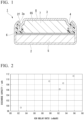
- FIG. 1 is a cross-sectional view showing a button-shaped alkaline battery according to a first embodiment of the present invention.
- a battery 1 of the present embodiment is a battery in which a positive electrode mixture, a negative electrode mixture, an electrolytic solution, and the like, which will be described later, are accommodated in a flat metal container.
- a metal can includes a positive electrode can 2 and an negative electrode can 3.
- the positive electrode can 2 is formed of, for example, stainless steel (SUS) or a material obtained by plating stainless steel with nickel.
- the positive electrode can 2 is molded, for example, in a flat cylindrical shape (a shallow cup shape).
- the positive electrode can 2 accommodates a positive electrode mixture 5 and functions as a positive electrode current collector.
- the negative electrode can 3 is formed of a clad material having a three-layer structure including, for example, a nickel outer surface layer, a metal layer made of stainless steel (SUS), and a current collector layer made of copper.
- the negative electrode can 3 is molded, for example, in a flat cylindrical shape (a shallow cup shape).
- the negative electrode can 3 has a circular opening portion 3a formed to be folded back.
- a ring-shaped gasket 4 made of nylon is mounted on the opening portion 3a.
- the negative electrode can 3 is fitted to a circular opening portion 2f of the positive electrode can 2 from an opening portion 3a side on which the gasket 4 is mounted.
- the opening portion 2f of the positive electrode can 2 is sealed by being crimped toward the gasket 4.
- a disk-shaped (button-shaped or coin-shaped) container (case) 8 is formed.
- a sealed space 8S is formed inside the container 8.
- the gasket 4 insulates and seals the positive electrode can 2 and the negative electrode can 3.
- the positive electrode mixture 5, a separator 6, a negative electrode mixture 7, and an electrolytic solution (not shown) are accommodated in the sealed space 8S.
- the positive electrode mixture 5 is disposed on a positive electrode can 2 side with the separator 6 interposed therebetween, and the negative electrode mixture 7 is disposed on a negative electrode can 3 side.
- the positive electrode mixture 5 includes a positive electrode active material, a conductive agent, an electrolytic solution, a binder, an additive, and the like.
- the positive electrode active material is preferably a material that can be used as a positive electrode active material in a case where zinc or a zinc alloy is used as a negative electrode active material.
- a mixture of silver oxide powder (Ag 2 O powder) and manganese dioxide powder (MnO 2 powder) can be used as the positive electrode active material.
- Silver nickel oxide (AgNiO 2 ) may be further added to the positive electrode active material.
- conductive auxiliary agent for example, graphite or the like can be used.
- additive for example, a hydrogen storage alloy (LaNi 5 ) can be used.
- the positive electrode active material is the mixture of silver oxide powder and manganese dioxide powder
- manganese dioxide is preferably contained in the positive electrode mixture in an amount of 50% by mass or less.
- a manganese dioxide content in the positive electrode mixture is preferably 25% to 50% by mass and more preferably 25% to 44% by mass.
- the manganese dioxide content By setting the manganese dioxide content to be in the above-described range, the amount of silver oxide used can be reduced, and the cost can be reduced. Furthermore, an effect of improving discharge characteristics can be obtained, and particularly, it is possible to prevent a decrease in capacity at the end of discharging in a case of discharging with a large current.
- manganese dioxide having physical properties of a MnO 2 content of 91.0% or more, an amount of particles having a particle size of 75 ⁇ m or less of 80.0% or more, and an alkaline potential of 220 mV or more can be used.
- the negative electrode mixture 7 preferably contains, for example, a negative electrode active material, a thickener, an electrolytic solution (alkaline aqueous solution), and other additives such as zinc oxide.
- Zinc oxide (ZnO) functions as a conductivity stabilizer.
- the additives may include a viscoelasticity adjuster, a resin powder, and the like.
- the negative electrode active material for example, zinc (Zn) powder or zinc alloy powder can be used.
- the thickener for example, polyacrylic acid, carboxymethyl cellulose, or a mixture of polyacrylic acid and carboxymethyl cellulose is preferable. By using carboxymethyl cellulose or polyacrylic acid, lyophilicity and liquid retention of the negative electrode mixture 7 with respect to the electrolytic solution can be improved.
- an alkaline aqueous solution particularly, a mixed aqueous solution of a potassium hydroxide (KOH) aqueous solution and a sodium hydroxide (NaOH) aqueous solution is preferably used.
- the negative electrode mixture 7 preferably contains potassium hydroxide and sodium hydroxide at a ratio of 89:11 to 96:4 in terms of molar ratio, and more preferably at a ratio of 89.70:10.30 to 95.76:4.24 in terms of molar ratio.
- the negative electrode mixture 7 In combination with the electrolytic solution (KOH aqueous solution having a concentration of 30% to 50%) having the composition described later, the negative electrode mixture 7 not only exhibits excellent conductivity but also holds the electrolytic solution around the negative electrode active material (Zn) until the end of discharging. As a result, it is possible to improve a utilization efficiency of the active material, and it is possible to provide an alkaline battery having excellent discharge characteristics.
- a potassium hydroxide aqueous solution having a concentration of 45% and a sodium hydroxide aqueous solution having a concentration of 27% are used as the alkaline aqueous solution used in the negative electrode mixture 7.
- An input ratio between the potassium hydroxide aqueous solution and the sodium hydroxide aqueous solution is set to a range of 88:12 to 95:5 in terms of mass ratio, and can be set to, for example, 91:9 in terms of mass ratio.
- the potassium hydroxide and the sodium hydroxide in the negative electrode mixture 7 are included in the negative electrode mixture 7 at a molar ratio of 89:11 to 96:4, and more specifically, at a ratio of 89.70:10.30 to 95.76:4.24.
- the concentration and the input ratio of the alkaline aqueous solution to be input can be appropriately adjusted to achieve the molar ratio between potassium hydroxide and sodium hydroxide in the negative electrode mixture 7 described above.
- concentration of the alkaline aqueous solution in the present specification is expressed in terms of mass fraction (mass percent concentration) unless otherwise specified.
- the viscoelasticity adjusting material is blended as necessary to adjust viscoelasticity of the negative electrode mixture 7 to a viscoelasticity such that good handling properties are obtained and productivity is improved.
- a resin powder that does not react with a strongly alkaline electrolytic solution is used as the viscoelasticity adjusting material.
- polytetrafluoroethylene, polypropylene, polyamide, polyethylene powder, an acrylic resin, and the like are used as the viscoelasticity adjusting material.
- a state that does not react with the electrolytic solution means a state that does not chemically react with the electrolytic solution and does not absorb the electrolytic solution.
- the separator 6 is interposed between the positive electrode mixture 5 and the negative electrode mixture 7.
- a separator used for a separator of a battery can be applied, and particularly a separator having an electrical resistance of 250 m ⁇ cm 2 or less is preferable.
- the separator 6 consists of cellophane, a grafted membrane, and the like. These materials may be used in combination, or a required number of films or sheets consisting of the same type of material may be stacked to be used.
- an alkaline battery having excellent conductivity in combination with an electrolytic solution described later can be configured.
- a potassium hydroxide aqueous solution having a concentration of 40% to 50% can be used as the electrolytic solution with which the container 8 is filled.
- the concentration of the potassium hydroxide aqueous solution is preferably 44% to 50% and more preferably 45% to 50%.
- the concentration of the electrolytic solution is within the above-described range, sufficient conductivity can be obtained.
- the higher the concentration of potassium hydroxide the better the conductivity.
- the concentration of potassium hydroxide exceeds 50%, there is a concern that the conductivity may deteriorate, and thus there is a concern that a sufficient discharge capacity may not be obtained.
- the positive electrode mixture 5 and the negative electrode mixture 7 are first produced.
- the electrolytic solution is injected into the positive electrode can 2, and then the positive electrode mixture 5 is placed in the positive electrode can 2.
- the separator 6 and the gasket 4 are incorporated into the positive electrode can 2, and then the electrolytic solution is injected.
- the negative electrode mixture 7 is disposed, and then the negative electrode can 3 is incorporated.
- the opening portion 2f of the positive electrode can 2 is crimped to seal the case 8. In this manner, the alkaline battery 1 shown in FIG. 1 can be obtained.
- the positive electrode can 2 is filled with the positive electrode mixture 5 molded into a pellet shape.
- the separator 6 is laid on the positive electrode mixture 5 and the gasket 4 is press-fitted into the positive electrode can 2.
- the gel-like negative electrode mixture 7 is placed on the separator 6, and after filling with the electrolytic solution, the negative electrode can 3 is placed thereon.
- the opening portion 2f of the positive electrode can 2 is crimped to seal the case 8. In this manner, the alkaline battery 1 shown in FIG. 1 can be obtained.
- a negative electrode mixture 7 having good handleability in which potassium hydroxide and sodium hydroxide are blended as an electrolytic solution at a molar ratio of 89:11 to 96:4, is used. Therefore, a required amount of the negative electrode mixture 7 can be placed without any problem.
- manganese dioxide is blended in the positive electrode mixture at a suitable ratio of 50% by mass or less, so that the amount of expensive silver oxide used is reduced. Therefore, the cost can be reduced.
- a potassium hydroxide aqueous solution having a concentration of 40% to 50% is contained in the electrolytic solution, and the molar ratio between potassium hydroxide and sodium hydroxide as the electrolytic solution contained in the gel-like negative electrode is set to a suitable ratio of 89:11 to 96:4. Therefore, even under a heavy load condition, it is possible to prevent a decrease in capacity until the end of discharging, and it is possible to provide the alkaline battery 1 having excellent discharge characteristics.
- the alkaline battery 1 including the container 8 consisting of the positive electrode can 2 and the negative electrode can 3 made of metal has been described, but the present invention is not limited to this case.
- the container is not limited to a metal container, and for example, the container may be configured as a positive electrode container and a negative electrode container, which are formed of a laminated film of a metal foil and a resin layer.
- the configuration of the container is not particularly limited, and any form of container applied to a general battery may be used.
- a prototype of a button-shaped battery having the internal structure shown in FIG. 1 was produced and subjected to a test described below.
- a size of the button-shaped battery was set to a diameter of 11.6 mm and a height of 5.4 mm.
- a positive electrode can of the button-shaped battery was made of stainless steel, and a negative electrode can was formed of a clad material having a three-layer structure consisting of nickel, stainless steel, and copper.
- a positive electrode mixture, a separator, a negative electrode mixture, and an electrolytic solution are accommodated in a container consisting of the positive electrode can and the negative electrode can as shown in FIG. 1 . Furthermore, after a gasket was mounted, the positive electrode can was crimped and sealed to produce a prototype of an alkaline battery.
- the positive electrode mixture formed by mixing 65.0% by mass of silver oxide (Ag 2 O) as an active material, 31.0% by mass of manganese dioxide (MnO 2 ) containing an acrylic polymer as a binder, 3.0% by mass of graphite as a conductive auxiliary agent, and 1.0% by mass of a hydrogen storage alloy (LaNi 5 ) was press-molded to produce a pellet-shaped positive electrode.
- silver oxide Ag 2 O
- MnO 2 manganese dioxide
- a hydrogen storage alloy LaNi 5
- Five kinds of electrolytic solutions for a negative electrode mixture were produced using a potassium hydroxide aqueous solution having a concentration of 45% and a sodium hydroxide aqueous solution having a concentration of 27%, at mixing ratios described below such that a molar ratio between potassium hydroxide and sodium hydroxide in the negative electrode mixture was in a range of 83:17 to 96:4.
- Each prototype alkaline battery was produced by using each of the electrolytic solutions having the mixing ratios.
- the five kinds of mixing ratios are 83%, 90%, 92%, 93%, and 96% in terms of the molar ratio of potassium hydroxide.
- each prototype alkaline battery was produced by using, as the electrolytic solution, each of potassium hydroxide aqueous solutions having four compositions described below.
- the negative electrode can was incorporated, and the positive electrode can was crimped and sealed.
- a button-shaped prototype alkaline battery (so-called 44 size) having a diameter of 11.6 mm and a height of 5.4 mm was produced.
- a plurality of prototype alkaline batteries were prepared by using each of separators having electrical resistances of 176, 250, and 525 m ⁇ cm 2 .
- the electrical resistance of such a separator can be obtained by adjusting various conditions such as thicknesses of the cellophane and the grafted membrane, and a grafting ratio of the grafted membrane (a ratio obtained by dividing a weight of graft chains in graft polymerization by a weight of a base material).
- a constant current (10 mA) discharge test was conducted using each of the prototype alkaline batteries to obtain a discharge capacity value at a COV of 1.0 V.
- the constant current (10 mA) discharge test corresponds to a heavy load test in the button-shaped alkaline battery.
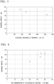
- Table 1 and FIG. 2 show a relationship between a molar ratio of potassium hydroxide and discharge capacity measurement results of the plurality of prototype alkaline batteries.
- a plurality of alkaline batteries are produced by changing the mixing molar ratio between potassium hydroxide and sodium hydroxide in the above-described electrolytic solution for a negative electrode mixture.
- the molar ratio between potassium hydroxide and sodium hydroxide is set to 100 in total. Therefore, a value obtained by dividing 100 by the molar ratio of potassium hydroxide shown in Table 1 corresponds to the molar ratio of sodium hydroxide.
- two of each of the prototype alkaline batteries having different molar ratios are produced and subjected to the test. Therefore, the obtained discharge capacity value indicates an average value of the two prototype alkaline batteries.
- Table 2 below and FIG. 3 show the discharge capacity measurement results of the plurality of prototype alkaline batteries obtained by using various separators having different electrical resistances.
- the molar ratio between potassium hydroxide and sodium hydroxide contained in the negative electrode mixture the molar ratio of potassium hydroxide is fixed to 93.
- the molar ratio between potassium hydroxide and sodium hydroxide is set to 100 in total. Therefore, the molar ratio of sodium hydroxide is 7.
- two alkaline batteries using separators having different electrical resistances are prepared and subjected to the test.
- the obtained discharge capacity value is an average value of the two prototype alkaline batteries.
- Table 2 Electrical resistance of separator/m ⁇ cm 2 Discharge capacity value/mAh 176 109 250 97 525 85
- the alkaline battery in which the electrical resistance of the separator exceeds 500 m ⁇ cm 2 has a low discharge capacity value. Therefore, the electrical resistance of the separator is desirably 500 m ⁇ cm 2 or less. Regarding the electrical resistance of the separator, it can be seen that in a case where the electrical resistance is 250 m ⁇ cm 2 or less, a discharge capacity can be sufficiently increased.
- Table 3 below and FIG. 4 show results of measuring a relationship between a concentration of potassium hydroxide and the discharge capacity in each of the prototype alkaline batteries.
- a plurality of prototype alkaline batteries are produced by changing the potassium hydroxide concentration in the electrolytic solution to be accommodated in the container together with the positive electrode or the negative electrode.
- [Table 3] KOH concentration in electrolytic solution/% by mass Discharge capacity value/mAh 30 70 44 91 45 106 50 106
- the discharge capacity value is significantly reduced in the prototype alkaline battery in which the concentration of potassium hydroxide in the electrolytic solution is 30%.
- the concentration of potassium hydroxide in the electrolytic solution is desirably adopted in a range of 40% to 50%, and it is considered that a range of 44% to 50% is desirable in order to reliably obtain an excellent discharge capacity.
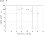
- Table 4 below and FIG. 5 show results of measuring a relationship between a blending ratio of manganese dioxide and the discharge capacity in each of the prototype alkaline batteries.
- a plurality of prototype alkaline batteries are produced by changing the blending ratio of manganese dioxide in the positive electrode mixture.
- Ratio of MnO 2 in positive electrode (% by mass) Discharge capacity value/mAh 0 104 25 102 31 106 39 100 42 102 49 90 59 79
- An alkaline battery shown in Table 4 and FIG. 5 in which a blending amount of manganese dioxide is set to 0% by mass is an alkaline battery to which a positive electrode active material consisting of only silver oxide is applied. By replacing 50% by mass or less of silver oxide with manganese dioxide, an alkaline battery having a small discharge capacity reduction ratio could be obtained.
- the blending amount of manganese dioxide is set to 44% by mass or less, more specifically, in a range of 25% to 44% by mass, it is possible to provide an alkaline battery in which a decrease in discharge capacity hardly occurs compared to a prototype alkaline battery using a positive electrode active material consisting of only silver oxide.
- the alkaline battery of the present disclosure has excellent discharge characteristics and can be reduced in cost, and thus has high industrial availability.
Landscapes
- Chemical & Material Sciences (AREA)
- Chemical Kinetics & Catalysis (AREA)
- Electrochemistry (AREA)
- General Chemical & Material Sciences (AREA)
- Engineering & Computer Science (AREA)
- Manufacturing & Machinery (AREA)
- Composite Materials (AREA)
- Inorganic Chemistry (AREA)
- Primary Cells (AREA)
- Battery Electrode And Active Subsutance (AREA)
- Cell Separators (AREA)
Applications Claiming Priority (2)
| Application Number | Priority Date | Filing Date | Title |
|---|---|---|---|
| JP2022182350A JP2024071871A (ja) | 2022-11-15 | 2022-11-15 | アルカリ電池及びアルカリ電池の製造方法 |
| PCT/JP2023/026831 WO2024105934A1 (ja) | 2022-11-15 | 2023-07-21 | アルカリ電池及びアルカリ電池の製造方法 |
Publications (2)
| Publication Number | Publication Date |
|---|---|
| EP4553932A1 true EP4553932A1 (de) | 2025-05-14 |
| EP4553932A4 EP4553932A4 (de) | 2026-03-25 |
Family
ID=91084423
Family Applications (1)
| Application Number | Title | Priority Date | Filing Date |
|---|---|---|---|
| EP23891096.2A Pending EP4553932A4 (de) | 2022-11-15 | 2023-07-21 | Alkalibatterie und verfahren zur herstellung einer alkalibatterie |
Country Status (6)
| Country | Link |
|---|---|
| US (1) | US20260100422A1 (de) |
| EP (1) | EP4553932A4 (de) |
| JP (1) | JP2024071871A (de) |
| KR (1) | KR20250108582A (de) |
| CN (1) | CN119895595A (de) |
| WO (1) | WO2024105934A1 (de) |
Family Cites Families (13)
| Publication number | Priority date | Publication date | Assignee | Title |
|---|---|---|---|---|
| US20040224229A1 (en) * | 2003-05-09 | 2004-11-11 | Mansuetto Michael F. | Alkaline cell with copper oxide cathode |
| JP5213002B2 (ja) | 2005-03-10 | 2013-06-19 | 日立マクセル株式会社 | 酸化銀電池 |
| JP2006302597A (ja) * | 2005-04-19 | 2006-11-02 | Sii Micro Parts Ltd | ボタン形アルカリ電池 |
| JP2010044906A (ja) * | 2008-08-11 | 2010-02-25 | Seiko Instruments Inc | 扁平形一次電池、扁平形一次電池の負極合剤及びその製造方法 |
| JP2010218711A (ja) * | 2009-03-13 | 2010-09-30 | Hitachi Maxell Ltd | 扁平形酸化銀電池 |
| CA2812180C (en) * | 2010-09-24 | 2019-03-05 | Zpower, Llc | Doped silver cathode |
| US9306223B2 (en) * | 2011-09-22 | 2016-04-05 | Eaglepicher Technologies, Llc | Electrolyte materials, thermal battery components, and thermal batteries for intermediate temperature applications |
| JP5999968B2 (ja) * | 2012-05-02 | 2016-09-28 | セイコーインスツル株式会社 | 扁平形一次電池、扁平形一次電池用負極合剤及びその製造方法 |
| JP6548417B2 (ja) * | 2015-03-18 | 2019-07-24 | セイコーインスツル株式会社 | 扁平形アルカリ一次電池 |
| JP6747793B2 (ja) * | 2015-09-16 | 2020-08-26 | マクセルホールディングス株式会社 | アルカリ二次電池 |
| JP6883441B2 (ja) * | 2016-03-07 | 2021-06-09 | セイコーインスツル株式会社 | 扁平形アルカリ一次電池 |
| JP6130012B2 (ja) * | 2016-03-22 | 2017-05-17 | セイコーインスツル株式会社 | 扁平形一次電池、扁平形一次電池用負極合剤及びその製造方法 |
| JP7564762B2 (ja) | 2021-05-28 | 2024-10-09 | 株式会社吉野工業所 | 化粧料容器 |
-
2022
- 2022-11-15 JP JP2022182350A patent/JP2024071871A/ja active Pending
-
2023
- 2023-07-21 US US19/113,614 patent/US20260100422A1/en active Pending
- 2023-07-21 CN CN202380067438.9A patent/CN119895595A/zh active Pending
- 2023-07-21 KR KR1020257008866A patent/KR20250108582A/ko active Pending
- 2023-07-21 EP EP23891096.2A patent/EP4553932A4/de active Pending
- 2023-07-21 WO PCT/JP2023/026831 patent/WO2024105934A1/ja not_active Ceased
Also Published As
| Publication number | Publication date |
|---|---|
| JP2024071871A (ja) | 2024-05-27 |
| US20260100422A1 (en) | 2026-04-09 |
| CN119895595A (zh) | 2025-04-25 |
| KR20250108582A (ko) | 2025-07-15 |
| EP4553932A4 (de) | 2026-03-25 |
| WO2024105934A1 (ja) | 2024-05-23 |
Similar Documents
| Publication | Publication Date | Title |
|---|---|---|
| US7169508B2 (en) | Method of manufacturing anode compositions for use in rechargeable electrochemical cells | |
| KR101769630B1 (ko) | 이차 아연 배터리용의 페이스트된 아연 전극 | |
| EP1790024A1 (de) | Alkalibatterie mit mno<sb>2</sb>/niooh-aktivmaterial | |
| KR20050016477A (ko) | 밀폐형 니켈 아연 일차전지 | |
| WO1997017737A1 (en) | Rechargeable alkaline cells containing zinc anodes without added mercury | |
| CA2389907A1 (en) | Small format, high current density flat plate rechargeable electrochemical cell | |
| EP1445812A1 (de) | Alkalibatterie | |
| EP2132810B1 (de) | Mehrschichtige positiv-elektrodenstrukturen mit einer silberhaltigen schicht für miniaturzellen | |
| EP3439080B1 (de) | Negativelektrode für alkalische sekundärbatterie, alkalische sekundärbatterie mit negativelektrode und verfahren zur herstellung einer negativelektrode | |
| JP5172181B2 (ja) | 亜鉛アルカリ電池 | |
| US9040196B2 (en) | Alkaline primary battery | |
| JP2005197230A (ja) | ボタン形アルカリ電池およびその製造方法 | |
| EP1990852A1 (de) | Alkaline-Trockenbatterie | |
| JP5545975B2 (ja) | 鉛蓄電池用正極活物質及びそれを充填して成る鉛蓄電池用正極板 | |
| EP4553932A1 (de) | Alkalibatterie und verfahren zur herstellung einer alkalibatterie | |
| US20200388838A1 (en) | Alkaline battery | |
| JP6434826B2 (ja) | 扁平形アルカリ一次電池及びその製造方法 | |
| JP6734155B2 (ja) | アルカリ電池 | |
| JP2022143474A (ja) | アルカリ乾電池 | |
| JP2002117859A (ja) | アルカリ電池 | |
| EP4401161A1 (de) | Alkalibatterie | |
| JP5135579B2 (ja) | 扁平形アルカリ電池 | |
| CN1314719A (zh) | 碱性蓄电池用非烧结式正电极及碱性蓄电池 | |
| US20070207382A1 (en) | Positive plate for alkaline secondary batteries and alkaline secondary battery | |
| WO2025005095A1 (ja) | アルカリ乾電池 |
Legal Events
| Date | Code | Title | Description |
|---|---|---|---|
| STAA | Information on the status of an ep patent application or granted ep patent |
Free format text: STATUS: THE INTERNATIONAL PUBLICATION HAS BEEN MADE |
|
| PUAI | Public reference made under article 153(3) epc to a published international application that has entered the european phase |
Free format text: ORIGINAL CODE: 0009012 |
|
| STAA | Information on the status of an ep patent application or granted ep patent |
Free format text: STATUS: REQUEST FOR EXAMINATION WAS MADE |
|
| 17P | Request for examination filed |
Effective date: 20250207 |
|
| AK | Designated contracting states |
Kind code of ref document: A1 Designated state(s): AL AT BE BG CH CY CZ DE DK EE ES FI FR GB GR HR HU IE IS IT LI LT LU LV MC ME MK MT NL NO PL PT RO RS SE SI SK SM TR |
|
| DAV | Request for validation of the european patent (deleted) | ||
| DAX | Request for extension of the european patent (deleted) | ||
| A4 | Supplementary search report drawn up and despatched |
Effective date: 20260223 |
|
| RIC1 | Information provided on ipc code assigned before grant |
Ipc: H01M 6/06 20060101AFI20260218BHEP Ipc: H01M 4/06 20060101ALI20260218BHEP Ipc: H01M 6/02 20060101ALI20260218BHEP Ipc: H01M 50/489 20210101ALI20260218BHEP Ipc: H01M 4/36 20060101ALI20260218BHEP Ipc: H01M 4/54 20060101ALI20260218BHEP Ipc: H01M 4/50 20100101ALI20260218BHEP Ipc: H01M 6/04 20060101ALI20260218BHEP Ipc: H01M 6/22 20060101ALI20260218BHEP |