EP4554052A1 - Procédé de fabrication d'un noyau statorique comprenant des canaux de refroidissement - Google Patents
Procédé de fabrication d'un noyau statorique comprenant des canaux de refroidissement Download PDFInfo
- Publication number
- EP4554052A1 EP4554052A1 EP24208106.5A EP24208106A EP4554052A1 EP 4554052 A1 EP4554052 A1 EP 4554052A1 EP 24208106 A EP24208106 A EP 24208106A EP 4554052 A1 EP4554052 A1 EP 4554052A1
- Authority
- EP
- European Patent Office
- Prior art keywords
- stator
- cooling
- hole
- holes
- rotor
- Prior art date
- Legal status (The legal status is an assumption and is not a legal conclusion. Google has not performed a legal analysis and makes no representation as to the accuracy of the status listed.)
- Pending
Links
Images


Classifications
-
- H—ELECTRICITY
- H02—GENERATION; CONVERSION OR DISTRIBUTION OF ELECTRIC POWER
- H02K—DYNAMO-ELECTRIC MACHINES
- H02K1/00—Details of the magnetic circuit
- H02K1/06—Details of the magnetic circuit characterised by the shape, form or construction
- H02K1/12—Stationary parts of the magnetic circuit
- H02K1/20—Stationary parts of the magnetic circuit with channels or ducts for flow of cooling medium
-
- H—ELECTRICITY
- H02—GENERATION; CONVERSION OR DISTRIBUTION OF ELECTRIC POWER
- H02K—DYNAMO-ELECTRIC MACHINES
- H02K15/00—Processes or apparatus specially adapted for manufacturing, assembling, maintaining or repairing of dynamo-electric machines
- H02K15/02—Processes or apparatus specially adapted for manufacturing, assembling, maintaining or repairing of dynamo-electric machines of stator or rotor bodies
- H02K15/021—Magnetic cores
- H02K15/0273—Laminating the cores
Definitions
- the invention relates to a method for producing a stator core for an electrical machine and to a corresponding stator core. Furthermore, the invention relates to an electrical machine and a motor vehicle having such a stator core, as well as to a stator lamination for use in producing the stator core.
- Rotating electrical machines that convert electrical energy into kinetic energy or vice versa are generally known in the art. Such electrical machines often comprise a rotating rotor surrounded by a stationary stator.
- the stator also called the stand, typically has a stator core made of layered, insulated individual laminations with slots into which a stator winding is housed.
- a stator core made of layered, insulated individual laminations with slots into which a stator winding is housed.
- the object of the invention is to provide an improved solution for cooling a stator, by means of which the disadvantages of previous solutions can preferably be avoided. It is preferably an object of the invention to provide a simple-to-manufacture solution by means of which effective stator cooling can be realized with preferably low pressure losses.
- a method for manufacturing a stator core for a (e.g., rotating) electric machine e.g., for a vehicle electric motor.
- the method comprises providing a plurality of identically constructed (e.g., annular) stator laminations (e.g., made of electrical steel). Preferably, all of the plurality of stator laminations are thus identical parts.
- the plurality of identically constructed stator laminations preferably comprise a (e.g., annular and/or circumferentially closed) base body.
- the plurality of identically constructed stator laminations and/or their respective base bodies each comprise a (e.g., central) rotor through-hole (e.g., in the center of the base body) and a plurality of cooling through-holes, preferably arranged concentrically and/or annularly around the rotor through-hole.
- the cooling through-holes are preferably each (e.g., significantly) smaller than the rotor through-hole.
- the method further comprises stacking (e.g., aligned) the plurality of identical stator laminations along a central axis to form a stator lamination stack, preferably such that the respective centers of the rotor through-holes all lie (e.g., aligned) on the central axis.
- the stacked rotor through-holes form a (e.g., cylindrical and/or circumferentially closed) receiving space for a (e.g., rotatably mounted) rotor of the electric machine in the stator lamination stack.
- the stacked cooling through-holes form a plurality of cooling channels (e.g., arranged concentrically and/or annularly around the receiving space for the rotor) in the stator lamination stack.
- the cooling channels are each fluid-tight (e.g., oil-tight) and/or can be flowed through by a (e.g., gaseous and/or liquid) coolant.
- the method further comprises securing the stacked stator laminated core to form the stator core. This can be done, for example, by means of at least one (e.g., rod-shaped) holding element (e.g., a clamping bolt). Additionally or alternatively, the securing can also include welding, screwing, gluing, pressing, and/or baking the stacked stator laminated core.
- at least one (e.g., rod-shaped) holding element e.g., a clamping bolt.
- the securing can also include welding, screwing, gluing, pressing, and/or baking the stacked stator laminated core.
- the method provides that at least two, preferably at least three, of the plurality of cooling through-holes of each of the plurality of identical stator laminations are designed differently, preferably each having (e.g. viewed from the same viewing direction, in particular along the central axis) different hole cross-sections (e.g. in a plane perpendicular to the central axis and/or perpendicular to a respective hole extension direction).
- each of the stator laminations may have at least one first cooling through-hole with a first hole cross-section and/or at least one second cooling through-hole with a second hole cross-section and/or at least one third cooling through-hole with a third hole cross-section, wherein the respective hole cross-sections are preferably each formed differently from one another (e.g. have a different shape and/or size).
- cooling channels with varying cooling channel cross-sections can be easily created. These are characterized by improved heat dissipation properties compared to cooling channels with a constant cross-section.
- the plurality of cooling through-holes of each of the plurality of identical stator laminations can have at least one symmetrical (e.g., mirror-symmetrical) cooling through-hole.
- this has an axially symmetrical hole cross-section.
- the at least one symmetrical cooling through-hole can have a hole cross-section that is substantially kidney-shaped and/or rectangular with a (e.g., centrally or symmetrically) indented longitudinal side.
- the plurality of cooling through-holes of each of the plurality of identical stator laminations can have at least one asymmetrical cooling through-hole.
- This preferably has a non-axisymmetrical hole cross-section.
- the at least one asymmetrical cooling through-hole can have a substantially boot-shaped hole cross-section, e.g., in the form of a boot turned to the right.
- the plurality of cooling through-holes of each of the plurality of identical stator laminations can have at least one further asymmetrical cooling through-hole.
- This preferably has a further non-axisymmetrical hole cross-section.
- the hole cross-section of the at least one further asymmetrical cooling through-hole is mirror-inverted and/or laterally reversed to the hole cross-section of the at least one asymmetrical cooling through-hole.
- the at least one further asymmetrical cooling through-hole can have a substantially boot-shaped hole cross-section, e.g., in the form of a boot turned to the left. The inventors have found that particularly advantageous cooling channel geometries can be created by the protruding hole cross-sections.
- the at least one symmetrical cooling through-hole (e.g., of each stator lamination) can have a plurality (e.g., twenty) symmetrical cooling through-holes. These are preferably arranged (e.g., exclusively or substantially) in a (e.g., first) 120° circular ring segment around a center point of the respective rotor through-hole (e.g., of the corresponding stator lamination) (e.g., evenly distributed).
- the plurality of symmetrical cooling through-holes (e.g., of each stator lamination) can all be equally spaced from the center point of the respective rotor through-hole and/or can be regularly distributed in the circumferential direction within a (e.g., first) third-circular ring segment (e.g., around the center point of the respective rotor through-hole).
- the at least one asymmetric cooling through-hole (e.g., of each stator lamination) can also have a plurality (e.g., twenty) asymmetric cooling through-holes. These are preferably arranged (e.g., exclusively or substantially) in a (e.g., second) 120° circular ring segment around the center of the respective rotor through-hole (e.g., of the corresponding stator lamination) (e.g., evenly distributed).
- the plurality of asymmetric cooling through-holes (e.g., of each stator lamination) can all be equidistant from the center of the respective rotor through-hole and/or can be regularly distributed in the circumferential direction within a (e.g., second) third-circular ring segment (e.g., around the center of the respective rotor through-hole).
- the at least one further asymmetrical cooling through-hole (e.g., of each stator lamination) can also have a plurality (e.g., twenty) further asymmetrical cooling through-holes. These are preferably arranged (e.g., exclusively or substantially) in a (e.g., third) 120° circular ring segment around the center of the respective rotor through-hole (e.g., of the corresponding stator lamination) (e.g., evenly distributed).
- the plurality of further asymmetrical cooling through-holes (e.g., of each stator lamination) can all be equally spaced from the center of the respective rotor through-hole and/or can be regularly distributed in the circumferential direction within a (e.g., third) third-circular ring segment (e.g., around the center of the respective rotor through-hole).
- a third-circular ring segment e.g., around the center of the respective rotor through-hole.
- the third-part division of the cooling through-holes advantageously enables, for example, corresponding 120° twisting of the stator laminations during stacking, joining different hole cross-sections and thus creating a varying cooling channel geometry along a respective extension direction of the cooling channels.
- the cooling through-holes of each of the plurality of identical stator laminations can all each have a concave-pentagonal hole cross-section (e.g., with rounded corners).
- the concave-pentagonal hole cross-sections of at least two, preferably at least three, of the cooling through-holes of each stator lamination preferably differ (e.g., in shape and/or size). The inventors have determined that this hole cross-sectional shape is particularly suitable for creating advantageous cooling channel geometries.
- the stacking step may comprise rotating at least two of the plurality of identical stator laminations relative to one another (e.g., by an angle of 120°) about the central axis. This is preferably done in such a way that (e.g., exclusively) differently configured cooling through-holes (e.g., cooling through-holes with different hole cross-sections) adjoin one another and/or the plurality of cooling channels (e.g., formed by the stacked cooling through-holes) each have a varying cooling channel cross-section (e.g., flow cross-section) along a respective extension direction parallel to the central axis.
- differently configured cooling through-holes e.g., cooling through-holes with different hole cross-sections
- the plurality of cooling channels e.g., formed by the stacked cooling through-holes
- a stator lamination to be attached to a stack end can be joined to the end stator lamination at an angle (e.g., by 120°), so that, for example, a symmetrical cooling through-hole of this attached stator lamination borders an asymmetrical cooling through-hole of the end stator lamination.
- This advantageously allows cooling channels to be created with cooling channel geometries that vary along their respective extension directions, enabling better heat dissipation compared to consistently constant channel geometries.
- the stacking step can also comprise joining at least two of the plurality of identical stator laminations together in such a way that (e.g. exclusively) differently designed cooling through-holes (e.g. with different hole cross-sections) adjoin one another.
- the plurality of cooling channels thus each have a varying cooling channel cross-section along a respective direction of extension parallel to the central axis.
- one or more stator laminations can be rotated about the central axis during joining.
- stator lamination it is also possible in principle for a stator lamination to be joined to be It is turned (e.g., flipped) in its main extension plane, for example, to create a contiguous interface between differently shaped cooling through-holes. Varying cooling channel geometries can also be advantageously created in this way.
- the stacking step may comprise grouping the plurality of identical stator laminations into a plurality of sub-stacks each comprising identically oriented stator laminations.
- the plurality of sub-stacks may each comprise an identical (e.g., predetermined) number of identically oriented stator laminations. Due to the identical orientation of the stator laminations in a sub-stack, the respective cooling channels within a sub-stack may preferably each have a constant cross-section along their respective extension direction parallel to the central axis.
- the stacking step can involve rotating (e.g., adjacent) partial stacks relative to one another (e.g., by an angle of 120°) around the central axis and/or joining the partial stacks such that (e.g., exclusively) differently shaped cooling through-holes (e.g., with different hole cross-sections) adjoin one another.
- cooling channels with varying cooling channel geometries along their extension direction can again be advantageously created in this way, whereby the periodicity or the specific shape of the cooling channel paths can be varied by grouping or using partial stacks.
- the plurality of identical stator laminations can each have a plurality of stator teeth (e.g., evenly distributed and/or evenly spaced from one another).
- each of the stator teeth can have a tooth root, via which the respective stator tooth can be connected (e.g., integrally) to the (e.g., annular) base body of the respective stator lamination, and a tooth tip (e.g., opposite and/or oppositely oriented to the tooth root).
- the respective stator teeth e.g., their respective tooth tips
- the plurality of identical stator laminations can each have a plurality of stator slots (e.g., evenly distributed and/or evenly spaced apart) for accommodating a stator winding.
- the respective stator slots are each formed between two adjacent stator teeth.
- each of the stator slots can be bounded by a stator tooth both to the left and right when viewed in the circumferential direction.
- a number of cooling through-holes can be equal to a number of stator slots.
- each of the plurality of identical stator laminations can have the same number of cooling through-holes as stator slots.
- one of the respective cooling through-holes is assigned to one of the respective stator slots.
- each of the cooling through-holes can be arranged radially outwardly and/or radially aligned with one of the respective stator slots.
- the cooling through-holes can thus each have a greater distance from the center of the rotor through-hole than the respective stator slots.
- each of the cooling through-holes can be arranged adjacent to a respective slot base of one of the respective stator slots and/or in the region of a respective slot base of one of the respective stator slots. Overall, this advantageously allows for reliable heat dissipation from a stator winding accommodated in the stator slots.
- the plurality of identical stator laminations can each be substantially annular.
- the base body can be formed as a ring base body.
- the plurality of identical stator laminations can each have at least one (e.g., radially outwardly directed) tab for receiving at least one (e.g., pin-shaped) retaining element.
- the respective tabs are slotted and/or open at least in sections.
- the stacked tabs can form a preferably straight through-opening into which the at least one retaining element (e.g., in the form of a clamping bolt) can be received. This advantageously allows for secure fixation of the stator lamination stack.
- stator lamination stack and/or the stator core can comprise exclusively identical stator laminations.
- stator laminations of the stator lamination stack and/or the stator core can be exclusively identical parts. This advantageously simplifies manufacturing and reduces manufacturing costs.
- the receiving space for the rotor of the electric machine can have a substantially cylindrical shape.
- the receiving space for the rotor of the electric machine is formed symmetrically around the central axis.
- each of the plurality of cooling channels can have a varying cooling channel cross-section (e.g., in a plane perpendicular to the central axis) along a respective direction of extension parallel to the central axis.
- the shape and/or size of the cooling channel cross-section of each of the plurality of cooling channels can change along the respective direction of extension parallel to the central axis (e.g., as a result of stacking differently configured cooling through-holes).
- the plurality of cooling channels preferably do not have a constant cooling channel cross-section along their respective direction of extension. This can advantageously have a positive influence on the flow behavior and heat dissipation.
- each of the plurality of cooling channels can each have a plurality of (e.g. regular) changes of direction (e.g. changes of direction), preferably in the radial direction and the circumferential direction, along a respective direction of extension parallel to the central axis.
- each of the plurality of cooling channels can have a plurality of changes of direction in the radial direction and/or a plurality of changes of direction in the circumferential direction along its respective direction of extension.
- the terms radial direction and circumferential direction can, for example, refer to the central axis of the stator laminated core or the stator laminated core itself.
- the radial direction can be defined perpendicular to the central axis and the circumferential direction around the central axis. This can also advantageously have a positive influence on the flow behavior and heat dissipation.
- each of the plurality of cooling channels can completely penetrate the stator core.
- each of the plurality of cooling channels can extend continuously (e.g., without interruption) through the stator core from a first end surface of the stator core (e.g., oriented perpendicular to the central axis) to a second end surface of the stator core (e.g., oriented perpendicular to the central axis).
- a further independent aspect of the present disclosure relates to a (e.g., hollow-cylindrical) stator core for a (e.g., rotating) electric machine (e.g., a vehicle electric motor).
- a (e.g., rotating) electric machine e.g., a vehicle electric motor.
- the stator core is formed according to a method as described herein. manufactured. Consequently, the aspects described herein in connection with the method, e.g., the possible designs of the stator laminations, are also intended to be disclosed and claimable in connection with the stator core. The same applies vice versa.
- the stator core has a (e.g., fixed) stator lamination stack made up of a plurality of identical stator laminations stacked along a central axis.
- the (e.g., stacked) stator laminations of the stator lamination stack are preferably at least partially rotated relative to one another (e.g., around the central axis).
- some of the stator laminations may be rotated by ⁇ 120° relative to a reference stator lamination of the stator lamination stack.
- the stator laminations may be stacked such that the second, fifth, seventh, etc. stator lamination is rotated by +120°, and the third, sixth, ninth, etc. stator lamination is rotated by -120° relative to the first stator lamination.
- the aforementioned stator core has a (e.g., cylindrical and/or circumferentially closed) receiving space for a (e.g., rotatably mounted) rotor of the electric machine.
- the receiving space is arranged symmetrically around the central axis.
- the stator core has a plurality of cooling channels (e.g., through which a coolant flows) (e.g., arranged concentrically around the receiving space for the rotor).
- each of the plurality of cooling channels has a varying (e.g., changing in shape and/or size) cooling channel cross-section (e.g., in a plane perpendicular to the central axis) and/or multiple changes of direction (e.g., in the radial direction and circumferential direction) along a respective extension direction parallel to the central axis.
- a varying (e.g., changing in shape and/or size) cooling channel cross-section e.g., in a plane perpendicular to the central axis
- multiple changes of direction e.g., in the radial direction and circumferential direction
- each of the plurality of cooling channels can have at least one change of direction in the radial direction and/or at least one change of direction in the circumferential direction along the respective direction of extension parallel to the central axis.
- each of the plurality of cooling channels can be displaced radially outward and/or radially inward in sections (e.g., with respect to the radial direction) along its respective direction of extension parallel to the central axis.
- each of the plurality of cooling channels can be displaced laterally to the left and/or laterally to the right in sections (e.g., with respect to the circumferential direction) along the respective direction of extension parallel to the central axis.
- each of the plurality of cooling channels has a periodic sequence of changes in direction in the radial direction and/or circumferential direction along the respective extension direction parallel to the central axis.
- each of the plurality of cooling channels can be designed in the form of an angular spiral helix and/or angular helix.
- each of the plurality of cooling channels can thus have a turbine geometry and/or be designed like a turbine.
- each of the plurality of cooling channels can be configured to guide a respective coolant flow (e.g., within the respective cooling channel) along a substantially helical and/or corkscrew-shaped flow path (e.g., along the respective cooling channel).
- a flow path can be configured in the form of a (e.g., angular) helical line.
- each of the plurality of cooling channels may be configured to guide a respective coolant flow on a flow path circulating along the respective extension direction parallel to the central axis.
- each of the plurality of cooling channels can have an axially symmetric cooling channel cross-section and/or a non-axisymmetric cooling channel cross-section in sections along the respective extension direction parallel to the central axis.
- sections with an axially symmetric cooling channel cross-section and sections with a non-axisymmetric cooling channel cross-section alternate periodically in the plurality of cooling channels.
- a further independent aspect of the present disclosure relates to a (e.g., rotating) electric machine (e.g., an electric motor) for a motor vehicle (e.g., a commercial vehicle).
- the electric machine has a stator.
- This in turn, has a stator core, as described herein, and a stator winding attached to the stator core. Consequently, the aspects described herein in connection with the stator core or its method of production are also intended to be disclosed and claimable in connection with the electric machine. The same applies vice versa.
- the electric machine has a rotor, which is preferably rotatably received in the receiving space of the stator core.
- the electric machine preferably further has a coolant supply. by means of which coolant can be supplied to the respective cooling channels of the stator core.
- the coolant supply can comprise a coolant pump and/or corresponding connecting lines.
- a further independent aspect of the present disclosure relates to a motor vehicle (e.g., a hybrid or electric vehicle) having an electric machine, as described herein, and/or a stator core, as described herein. Consequently, the aspects described in connection with the electric machine, the stator core, and the method for producing the same are also intended to be disclosed and claimable in connection with the motor vehicle. The same applies vice versa.
- the motor vehicle is a commercial vehicle (e.g., a hybrid commercial vehicle or electric commercial vehicle).
- a commercial vehicle can generally be understood to mean, for example, a vehicle whose design and equipment are specifically designed to transport people, transport goods, or tow trailers.
- the commercial vehicle can be a truck, a semi-trailer truck, a construction vehicle, a bus, and/or an agricultural machine (e.g., a tractor).
- a further independent aspect of the present disclosure relates to a stator lamination (e.g., made of electrical steel sheet), preferably having the features as disclosed herein and/or as described in any one of claims 1-14.
- the stator lamination is particularly preferably used in a method as described herein and/or as a component of a stator core as described herein. Consequently, the aspects described in connection with the method, the stator core, the electrical machine, and the motor vehicle, in particular stator lamination features, are also intended to be disclosed and claimable in connection with the stator lamination itself. The same applies vice versa.
- the stator lamination has a (e.g., annular) base body that has a (e.g., central and/or centrally located) rotor through-hole.
- the rotor through-hole can be formed symmetrically around a center point M.
- stator lamination has a plurality of stator teeth, each of which preferably has a tooth root connected to the base body (e.g., integrally formed in one piece) and a tooth tip opposite the tooth root.
- the respective tooth tips can each be aligned with the center point M of the rotor through-hole.
- stator lamination has a plurality of stator slots (e.g. for receiving a stator winding), wherein the stator slots are preferably each formed between two adjacent stator teeth.
- the stator lamination has a plurality of cooling through-holes (e.g., arranged concentrically and/or annularly around the rotor through-hole).
- the cooling through-holes are each assigned to one of the stator slots and/or arranged radially outwardly offset from the respective stator slot(s).
- the cooling through-holes have a plurality of first cooling through-holes with a (e.g., axially symmetric) first hole cross-section, wherein the plurality of first cooling through-holes are preferably arranged in a first 120° circular ring segment around the center of the rotor through-hole.
- the cooling through-holes have a plurality of second cooling through-holes with a (e.g., non-axially symmetric) second hole cross-section, wherein the plurality of second cooling through-holes are preferably arranged in a second 120° circular ring segment around the center of the rotor through-hole.
- cooling through-holes have a plurality of third cooling through-holes with a (e.g., further non-axisymmetric) third hole cross-section, wherein the plurality of third cooling through-holes are preferably arranged in a third 120° circular ring segment around the center of the rotor through-hole.
- extension direction of a cooling channel should preferably refer to its direction of longest extension and/or the direction pointing from its beginning to its end.
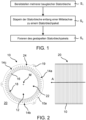
- FIG. 1 shows a schematic flow diagram of a method for producing a stator core 30 for an electrical machine (e.g., for a vehicle electric motor).
- the stator core 30, together with a stator winding (not shown) attached to the stator core 30, can be part of a stator of the electrical machine (not shown).
- a stator winding By applying a three-phase electric field to the stator winding, the stator winding and the An electromagnetic rotating field is generated in the stator core 30, which imparts a torque to a (not shown) magnetic rotor of the electrical machine and thereby sets it in motion.
- step S 1 several identical stator laminations 10 are provided, one of which is Figure 3 is shown by way of example.
- the stator laminations 10 are identical parts, each with the same dimensions and made of the same material. Consequently, the following explanations always preferably refer to each of the provided stator laminations 10.
- the stator laminations 10 can be made of electrical steel and/or an iron-silicon alloy.
- the stator laminations 10 can have a thickness between 0.1 and 1 mm.
- the stator laminations 10 can be punched and/or cut (e.g., laser-cut).
- the stator laminations 10 can be coated with an insulating varnish for insulation and/or corrosion protection.
- the stator laminations 10 can have a base body 10a (cf. Figure 3 ).
- the base body 10a can, for example, be annular (e.g., circular) and/or circumferentially closed.
- the stator laminations 10 and/or their base body 10a can have a rotor through-hole 12 and a plurality of cooling through-holes 14a, 14b, 14c (cf. Figure 3 ).
- the stator laminations 10 and/or their base bodies 10a can each be formed in one piece.
- the rotor through-hole 12 is preferably arranged centrally and/or centrally.
- the rotor through-hole 12 can be substantially circular.
- the rotor through-hole 12 can, for example, be punched, cut (e.g., laser-cut), and/or drilled.
- the rotor through-hole 12 can have a center point M and/or be formed symmetrically around the center point M.
- the cooling through-holes 14a, 14b, 14c can be arranged concentrically and/or in a circular ring around the rotor through-hole 12.
- all cooling through-holes 14a, 14b, 14c can be located or arranged on an imaginary circle around the center point M. Accordingly, the cooling through-holes 14a, 14b, 14c can all have the same (e.g., radial) distance from the center point M and/or from the rotor through-hole 12.
- the cooling through-holes 14a, 14b, 14c can also be punched, cut (e.g., laser-cut), and/or drilled, for example.
- the stator laminations 10 may further comprise several (e.g. sixty) stator teeth 16 (cf. Figure 3 ).
- Each of the stator teeth 16 can have a tooth root and a tooth tip, which are preferably connected to one another via a tooth shaft.
- the tooth root and tooth tip of a stator tooth 16 can be oriented and/or arranged opposite to one another.
- the tooth shaft can taper from the tooth root to the tooth tip, with the tooth tip preferably being widened.
- Each of the stator teeth 16 can be connected to the base body 10a via its tooth root (e.g., integrally).
- the tooth shanks and/or tooth tips can all be aligned with the center point M of the rotor through-hole 12. Accordingly, the stator teeth 16 can all point radially inward and/or protrude radially from the base body 10a.
- the stator teeth 16 are arranged equidistantly in a circumferential direction of the stator lamination 10 or the base body 10a.
- the stator teeth 16 can thus be arranged evenly distributed (e.g., in the circumferential direction) and/or evenly spaced from one another.
- Each of the stator laminations 10 may further comprise a plurality of stator slots 18 (cf. Figure 3 ).
- the stator slots 18 can each be arranged between two adjacent stator teeth 16. Accordingly, the stator slots 18 can also be arranged equidistantly and/or evenly distributed in the circumferential direction.
- the stator slots 18 can have two slot flanks and a slot base. The slot flanks can delimit the respective stator slots 18 in the circumferential direction, while the slot base delimits the respective stator slots 18 in the radial direction (e.g., radially outwards).
- the stator slots 18 can be open towards the center point M and/or towards the rotor through-hole 12.
- the slot base can in each case be arranged opposite the respective opening to the rotor through-hole 12.
- the cooling through-holes 14a, 14b, 14c are each assigned to one of the stator slots 18.
- one of the cooling through-holes 14a, 14b, 14c can be arranged on each of the stator slots 18.
- each stator lamination 10 can have an equal number of cooling through-holes 14a, 14b, 14c and stator slots 18.
- Each of the cooling through-holes 14a, 14b, 14c can be arranged radially outwardly offset from one of the stator slots 18.
- each of the cooling through-holes 14a, 14b, 14c can be arranged in alignment with a corresponding slot base of the stator slots 18 and radially outwardly offset from one another.
- each stator slot 18 can be assigned a cooling through-hole 14a, 14b, 14c.
- the cooling through-holes 14a, 14b, 14c are preferably not all of the same or identical design. Rather, at least two, preferably at least three, of the cooling through-holes 14a, 14b, 14c are of different design.
- the plurality of cooling through-holes 14a, 14b, 14c for example, partially have different hole cross-sections—when viewed from the same viewing direction.
- the plurality of cooling through-holes 14a, 14b, 14c in the present case have, by way of example, at least one first cooling through-hole 14a with a first hole cross-section, at least one second cooling through-hole 14b with a second hole cross-section and at least one third cooling through-hole 14c with a third hole cross-section.
- the first hole cross-section can, for example, have an axisymmetric shape (see detailed illustration below in Figure 3 ). Accordingly, the at least one first cooling through-hole 14a can also be referred to as a symmetrical through-hole.
- the first hole cross-section can be kidney-shaped and/or trough-shaped and/or in the form of a rectangle with an indented longitudinal side.
- the second hole cross-section can, for example, have a non-axisymmetric shape (see detailed illustration top left in Figure 3 ). Accordingly, the at least one second cooling through-hole 14b can also be referred to as an asymmetric through-hole.
- the second hole cross-section can be configured in the shape of a right-facing boot and/or in the shape of a rectangle with a notched corner.
- the third hole cross-section can also have a non-axisymmetric shape (see detailed illustration top right in Figure 3 ). Accordingly, the at least one third cooling through-hole 14c can also be referred to as a further asymmetric through-hole.
- the third hole cross-section can be configured in the shape of a left-facing boot and/or in the shape of a rectangle with a notched corner.
- the third hole cross-section is mirror-inverted and/or mirrored along an axis relative to the second hole cross-section.
- each of the cooling through-holes 14a, 14b, 14c has a concave-pentagonal hole cross-section with rounded corners.
- the first, second and third hole cross-section may be in the form of a concave pentagon with rounded corners, whereby the respective hole cross-sections differ.
- first, second and third hole cross-sections can each be based on a common basic cross-section 17 (cf. Figure 4 ).
- first, second, and third hole cross-sections can be based on a common basic cross-section 17 in the form of a rectangle with rounded corners.
- the first hole cross-section of the at least one first cooling through-hole 14a can, for example, result from the common basic cross-section 17 in that a triangular area, which is delimited, for example, by the long side and two half diagonals of the rectangle, is not excluded on one of the long sides of the rectangle.
- the second hole cross-section of the at least one second cooling through-hole 14b can, for example, result from the common basic cross-section 17 in that an irregularly quadrangular area, which is delimited, for example, by part of the long and transverse side of the rectangle, half of a perpendicular bisector, and half of a diagonal of the rectangle, is not excluded in one corner of the rectangle.
- the third hole cross-section of the at least one third cooling through-hole 14c can, for example, result from the rectangular basic cross-section 17 by mirroring the second hole cross-section at a perpendicular bisector of the rectangle.
- the at least one first cooling through-hole 14a has a plurality (e.g., twenty) first cooling through-holes 14a. These can, for example, be arranged evenly distributed in a first 120° circular ring segment 15a around the center point M of the respective rotor through-hole 12 (cf. Figure 3 ). Furthermore, the at least one second cooling through-hole 14b can also have a plurality of (e.g., twenty) second cooling through-holes 14b. These can, for example, be arranged evenly distributed in a second 120° circular ring segment 15b around the center point M of the respective rotor through-hole 12.
- the at least one third cooling through-hole 14c can also have a plurality of (e.g., twenty) third cooling through-holes 14c. These can, for example, be arranged evenly distributed in a third 120° circular ring segment 15c around the center point M of the respective rotor through-hole 12.
- the first, second, and third 120° circular ring segments 15a, 15b, 15c can have a common radius and/or together form a complete circle around the center point M.
- stator laminations 10 each have the same number of first, second and third cooling through-holes 14a, 14b, 14c.
- the stator laminations 10 may further comprise at least one tab 19 (cf. Figure 3 ).
- the at least one tab 19 can serve to receive at least one pin-shaped holding element 32.
- the at least one tab 19 can be formed onto the base body 10a and/or connected integrally to the base body 10a.
- the tab 19 can be directed radially outwards and/or protrude radially outwards from the base body 10a.
- the at least one tab 19 is slotted and/or open at least in sections.
- the at least one tab 19 can have a plurality of (e.g. three) tabs 19.
- the plurality of tabs 19 can be arranged on the stator lamination 10 so as to be evenly distributed in the circumferential direction.
- the plurality of tabs 19 can be at the same distance from one another and/or each have the same distance from the center point M.
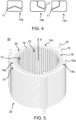
- step S 2 the plurality of identical stator laminations 10 are then stacked (e.g. stacked on top of each other) along a central axis A to form a stator lamination stack 20 (cf. Figures 2 , 5 , 6A and 6B ).
- the stacking is carried out such that the centers M of the rotor through-holes 12 of all stator laminations 10 lie on the central axis A.
- the stacking can preferably be carried out such that the rotor through-holes 12, stator teeth 16 and/or stator slots 18 of the stator laminations 10 are arranged in alignment with one another.
- the stacked rotor through-holes 12 can form a receiving space 22 for the rotor of the electrical machine in the stator core 20.
- the receiving space 22 for the rotor can, for example, be cylindrical and/or closed on the circumference.
- stacked at least one tab 19 can form at least one straight through-opening for at least one holding element 32 (e.g. a clamping bolt).
- at least one holding element 32 e.g. a clamping bolt
- the stacked cooling through-holes 14a, 14b, 14c can form a plurality of cooling channels 24 in the stator lamination stack 20.
- the number of cooling channels 24 can be equal to the number of cooling through-holes 14a, 14b, 14c and/or equal to the number of stator slots 18 of each of the stator laminations 10.
- the plurality of cooling channels 24 can be arranged concentrically around the receiving space 22.
- the plurality of cooling channels 24 can extend substantially parallel to the central axis M (see FIG. Figure 5 ).
- each of the plurality of cooling channels 24 may extend from a (e.g., perpendicular to the central axis M oriented) first (e.g.
- the plurality of cooling channels 24 can thus completely penetrate the stator laminated core 20.
- Each of the cooling channels 24 can be designed for a flow of a coolant (e.g. gaseous and/or liquid).
- the cooling channels 24 can be designed to be fluid-tight and/or gas-tight.
- the stator laminations 10 are not all stacked in the same orientation.
- the stacking preferably comprises a rotation of at least two of the stator laminations 10 relative to one another about the central axis and/or a joining of at least two stator laminations 10 such that differently formed cooling through-holes 14a, 14b, 14c adjoin one another.
- the stack may comprise a rotation of at least some of the stator laminations 10 by 120° about the central axis.
- the rotation occurs regularly, for example, such that a further stator lamination is added to a first stator lamination, rotated 120° clockwise about the central axis, and then another stator lamination is added to the further stator lamination, rotated 120° counterclockwise about the central axis. Accordingly, this can result in a periodic stator lamination sequence of untwisted stator laminations 10, 120° clockwise twisted stator laminations, and 120° counterclockwise twisted stator laminations.
- rotation is not limited to an angle of 120°.
- different arrangements of the differently shaped cooling through-holes 14a, 14b, 14c can result in different rotation angles.
- rotation does not necessarily have to occur between two stator laminations 10. It is also possible to stack several similarly oriented stator laminations 10 and/or partial stacks of similarly oriented stator laminations 10 in sections.
- the cooling channels 24 each have a varying cooling channel or flow cross-section along their respective extension direction parallel to the central axis A.
- the cooling channels 24 can additionally or alternatively each have several (e.g. regular) changes of direction in the radial and circumferential directions along their respective direction of extension (parallel to the central axis A).
- the cooling channels 24 can have at least one first segment 24a, which is preferably formed by the at least one first cooling through-hole with the first hole cross-section.
- the at least one first segment 24a can, for example, extend primarily in the circumferential direction and/or be configured to conduct the coolant in the circumferential direction.
- the cooling channels 24 can have at least one second segment 24b, which is preferably formed by the at least one second cooling through-hole with the second hole cross-section.
- the at least one second segment 24b can, for example, extend primarily in the radial direction and/or be designed to conduct the coolant in the radial direction (e.g., with respect to a coolant flow radially outward).
- the cooling channels 24 can have at least one third segment 24c, which is preferably formed by the at least one third cooling through-hole with the third hole cross-section.
- the at least one third segment 24c can, for example, extend primarily in the radial direction and/or be designed to conduct the coolant in the radial direction (e.g., with respect to a coolant flow radially inward).
- step S 3 the stacked stator laminated core 20 is finally fixed to form the stator core (cf. Figure 5 This can be done, for example, by means of at least one holding element 32 that is inserted into the housing. Additionally or alternatively, the stator core 20 can also be fixed in another form-fitting, force-fitting, and/or positive-locking manner.
- the fixing can include welding, screwing, gluing, pressing, and/or baking the stacked stator core.
Landscapes
- Engineering & Computer Science (AREA)
- Power Engineering (AREA)
- Manufacturing & Machinery (AREA)
- Iron Core Of Rotating Electric Machines (AREA)
Applications Claiming Priority (1)
| Application Number | Priority Date | Filing Date | Title |
|---|---|---|---|
| DE102023131105.0A DE102023131105A1 (de) | 2023-11-09 | 2023-11-09 | Verfahren zur Herstellung eines Statorkerns mit Kühlkanälen |
Publications (1)
| Publication Number | Publication Date |
|---|---|
| EP4554052A1 true EP4554052A1 (fr) | 2025-05-14 |
Family
ID=93257501
Family Applications (1)
| Application Number | Title | Priority Date | Filing Date |
|---|---|---|---|
| EP24208106.5A Pending EP4554052A1 (fr) | 2023-11-09 | 2024-10-22 | Procédé de fabrication d'un noyau statorique comprenant des canaux de refroidissement |
Country Status (2)
| Country | Link |
|---|---|
| EP (1) | EP4554052A1 (fr) |
| DE (1) | DE102023131105A1 (fr) |
Citations (5)
| Publication number | Priority date | Publication date | Assignee | Title |
|---|---|---|---|---|
| DE102009009819A1 (de) * | 2009-02-20 | 2010-08-26 | Sensor-Technik Wiedemann Gmbh | Statorblechpaket für elektrische Maschinen sowie Statorblech |
| US20190020231A1 (en) * | 2016-08-17 | 2019-01-17 | Atieva, Inc. | Motor Cooling System Utilizing Axial Cooling Channels |
| DE102019204029A1 (de) * | 2019-03-25 | 2020-10-01 | Audi Ag | Blechpaket für eine elektrische Maschine, elektrische Maschine sowie Verfahren zum Herstellen eines Blechpakets |
| WO2023028799A1 (fr) * | 2021-08-31 | 2023-03-09 | 舍弗勒技术股份两合公司 | Noyau statorique, ensemble stator, et moteur |
| EP4178080A1 (fr) * | 2021-11-09 | 2023-05-10 | MAHLE International GmbH | Machine électrique |
Family Cites Families (3)
| Publication number | Priority date | Publication date | Assignee | Title |
|---|---|---|---|---|
| JPS5956832A (ja) * | 1982-09-25 | 1984-04-02 | Fuji Electric Co Ltd | 電気機器の鉄心 |
| US5365132A (en) * | 1993-05-27 | 1994-11-15 | General Electric Company | Lamination for a dynamoelectric machine with improved cooling capacity |
| CN107210653A (zh) * | 2015-01-30 | 2017-09-26 | 普里派尔技术有限公司 | 具有液体冷却式齿的电机定子 |
-
2023
- 2023-11-09 DE DE102023131105.0A patent/DE102023131105A1/de active Pending
-
2024
- 2024-10-22 EP EP24208106.5A patent/EP4554052A1/fr active Pending
Patent Citations (5)
| Publication number | Priority date | Publication date | Assignee | Title |
|---|---|---|---|---|
| DE102009009819A1 (de) * | 2009-02-20 | 2010-08-26 | Sensor-Technik Wiedemann Gmbh | Statorblechpaket für elektrische Maschinen sowie Statorblech |
| US20190020231A1 (en) * | 2016-08-17 | 2019-01-17 | Atieva, Inc. | Motor Cooling System Utilizing Axial Cooling Channels |
| DE102019204029A1 (de) * | 2019-03-25 | 2020-10-01 | Audi Ag | Blechpaket für eine elektrische Maschine, elektrische Maschine sowie Verfahren zum Herstellen eines Blechpakets |
| WO2023028799A1 (fr) * | 2021-08-31 | 2023-03-09 | 舍弗勒技术股份两合公司 | Noyau statorique, ensemble stator, et moteur |
| EP4178080A1 (fr) * | 2021-11-09 | 2023-05-10 | MAHLE International GmbH | Machine électrique |
Also Published As
| Publication number | Publication date |
|---|---|
| DE102023131105A1 (de) | 2025-05-15 |
Similar Documents
| Publication | Publication Date | Title |
|---|---|---|
| DE69811057T2 (de) | Rotorkern für reluktanzmotoren | |
| DE102015215762A1 (de) | Blechpaket und Verfahren zu dessen Herstellung | |
| EP3189582B1 (fr) | Rotor d'une machine électrique, machine électrique et procédé de fabrication du rotor d'une machine électrique | |
| DE102004054277A1 (de) | Rotoranordnung für eine elektrische Maschine und Verfahren zur Herstellung einer Rotoranordnung | |
| DE102014111239B4 (de) | Blechpaket eines Stators oder eines Läufers sowie eine elektrische Maschine | |
| DE102019211713A1 (de) | Twistvorrichtung sowie Verfahren für eine Hairpin-Wicklung | |
| DE102020101149A1 (de) | Axialflussmaschine mit mechanisch fixierten Statorkernen mit radial verlaufenden Blechsegmenten | |
| EP3884570A1 (fr) | Procédé de fabrication d'un enroulement ondulé continu, enroulement ondulé continu, stator et machine électrique | |
| EP3193431A1 (fr) | Tole electrique dotee d'une ame imprimee | |
| EP3787155B1 (fr) | Arbre ainsi que rotor pour une machine électrique, machine électrique, véhicule et procédé de fabrication pour un rotor | |
| DE102018206003A1 (de) | Vorrichtung und Verfahren zur Ausrichtung einer Hairpinwicklung | |
| EP1315183B1 (fr) | Enroulement pour un transformateur ou une inductance | |
| DE10208564A1 (de) | Luftspule für rotierende elektrische Maschinen und deren Herstellungsverfahren | |
| EP4554052A1 (fr) | Procédé de fabrication d'un noyau statorique comprenant des canaux de refroidissement | |
| WO2015071090A2 (fr) | Rotor pour machine électrique asynchrone et procédé de fabrication d'un tel rotor | |
| EP3657635A1 (fr) | Rotor pour une machine asynchrone à géométrie de type barre optimisée en termes de pertes, machine asynchrone ainsi que procédé | |
| DE102013206045A1 (de) | Verfahren zur Herstellung eines Rotors und Rotor | |
| DE102018125838A1 (de) | Stator für eine elektrische Maschine und Verfahren zum Herstellen eines derartigen Stators | |
| DE102024102244A1 (de) | Elektrische leistungserzeugende Komponente und elektrische Radialflussmaschine | |
| DE102023124855A1 (de) | Stator einer elektrischen Rotationsmaschine und elektrische Rotationsmaschine | |
| DE102023100971A1 (de) | Verfahren zur Herstellung eines Stators einer elektrischen Rotationsmaschine, Stator einer elektrischen Rotationsmaschine und elektrische Rotationsmaschine | |
| DE102025125221A1 (de) | Stator-Eisenkern sowie ihn umfassender Elektromotor | |
| DE102023117311A1 (de) | Stator einer elektrischen Rotationsmaschine, Statoranordnung und elektrische Rotationsmaschine | |
| DE102024120459A1 (de) | Stator für eine Radialfluss-Doppelrotormaschine, Radialfluss-Doppelrotormaschine, Verfahren zur Herstellung eines Stators | |
| DE102019131036A1 (de) | Stator für eine elektrische Maschine |
Legal Events
| Date | Code | Title | Description |
|---|---|---|---|
| PUAI | Public reference made under article 153(3) epc to a published international application that has entered the european phase |
Free format text: ORIGINAL CODE: 0009012 |
|
| STAA | Information on the status of an ep patent application or granted ep patent |
Free format text: STATUS: THE APPLICATION HAS BEEN PUBLISHED |
|
| AK | Designated contracting states |
Kind code of ref document: A1 Designated state(s): AL AT BE BG CH CY CZ DE DK EE ES FI FR GB GR HR HU IE IS IT LI LT LU LV MC ME MK MT NL NO PL PT RO RS SE SI SK SM TR |
|
| STAA | Information on the status of an ep patent application or granted ep patent |
Free format text: STATUS: REQUEST FOR EXAMINATION WAS MADE |
|
| 17P | Request for examination filed |
Effective date: 20251010 |
|
| RAP1 | Party data changed (applicant data changed or rights of an application transferred) |
Owner name: TRATON AB |