EP4554343A1 - Dispositif de séparation pour substrats plats - Google Patents
Dispositif de séparation pour substrats plats Download PDFInfo
- Publication number
- EP4554343A1 EP4554343A1 EP24211617.6A EP24211617A EP4554343A1 EP 4554343 A1 EP4554343 A1 EP 4554343A1 EP 24211617 A EP24211617 A EP 24211617A EP 4554343 A1 EP4554343 A1 EP 4554343A1
- Authority
- EP
- European Patent Office
- Prior art keywords
- brush
- gripper
- separating device
- holding
- magazine
- Prior art date
- Legal status (The legal status is an assumption and is not a legal conclusion. Google has not performed a legal analysis and makes no representation as to the accuracy of the status listed.)
- Pending
Links
Images


Classifications
-
- H—ELECTRICITY
- H05—ELECTRIC TECHNIQUES NOT OTHERWISE PROVIDED FOR
- H05K—PRINTED CIRCUITS; CASINGS OR CONSTRUCTIONAL DETAILS OF ELECTRIC APPARATUS; MANUFACTURE OF ASSEMBLAGES OF ELECTRICAL COMPONENTS
- H05K3/00—Apparatus or processes for manufacturing printed circuits
- H05K3/0011—Working of insulating substrates or insulating layers
- H05K3/0044—Mechanical working of the substrate, e.g. drilling or punching
- H05K3/0052—Depaneling, i.e. dividing a panel into circuit boards; Working of the edges of circuit boards
-
- B—PERFORMING OPERATIONS; TRANSPORTING
- B25—HAND TOOLS; PORTABLE POWER-DRIVEN TOOLS; MANIPULATORS
- B25J—MANIPULATORS; CHAMBERS PROVIDED WITH MANIPULATION DEVICES
- B25J19/00—Accessories fitted to manipulators, e.g. for monitoring, for viewing; Safety devices combined with or specially adapted for use in connection with manipulators
- B25J19/02—Sensing devices
- B25J19/026—Acoustical sensing devices
-
- H—ELECTRICITY
- H10—SEMICONDUCTOR DEVICES; ELECTRIC SOLID-STATE DEVICES NOT OTHERWISE PROVIDED FOR
- H10P—GENERIC PROCESSES OR APPARATUS FOR THE MANUFACTURE OR TREATMENT OF DEVICES COVERED BY CLASS H10
- H10P72/00—Handling or holding of wafers, substrates or devices during manufacture or treatment thereof
- H10P72/04—Apparatus for manufacture or treatment
- H10P72/0428—Apparatus for mechanical treatment or grinding or cutting
-
- H—ELECTRICITY
- H10—SEMICONDUCTOR DEVICES; ELECTRIC SOLID-STATE DEVICES NOT OTHERWISE PROVIDED FOR
- H10P—GENERIC PROCESSES OR APPARATUS FOR THE MANUFACTURE OR TREATMENT OF DEVICES COVERED BY CLASS H10
- H10P72/00—Handling or holding of wafers, substrates or devices during manufacture or treatment thereof
- H10P72/70—Handling or holding of wafers, substrates or devices during manufacture or treatment thereof for supporting or gripping
- H10P72/78—Handling or holding of wafers, substrates or devices during manufacture or treatment thereof for supporting or gripping using vacuum or suction, e.g. Bernoulli chucks
-
- B—PERFORMING OPERATIONS; TRANSPORTING
- B25—HAND TOOLS; PORTABLE POWER-DRIVEN TOOLS; MANIPULATORS
- B25J—MANIPULATORS; CHAMBERS PROVIDED WITH MANIPULATION DEVICES
- B25J15/00—Gripping heads and other end effectors
- B25J15/04—Gripping heads and other end effectors with provision for the remote detachment or exchange of the head or parts thereof
- B25J15/0475—Exchangeable fingers
-
- H—ELECTRICITY
- H05—ELECTRIC TECHNIQUES NOT OTHERWISE PROVIDED FOR
- H05K—PRINTED CIRCUITS; CASINGS OR CONSTRUCTIONAL DETAILS OF ELECTRIC APPARATUS; MANUFACTURE OF ASSEMBLAGES OF ELECTRICAL COMPONENTS
- H05K2203/00—Indexing scheme relating to apparatus or processes for manufacturing printed circuits covered by H05K3/00
- H05K2203/01—Tools for processing; Objects used during processing
- H05K2203/0195—Tool for a process not provided for in H05K3/00, e.g. tool for handling objects using suction, for deforming objects, for applying local pressure
-
- H—ELECTRICITY
- H05—ELECTRIC TECHNIQUES NOT OTHERWISE PROVIDED FOR
- H05K—PRINTED CIRCUITS; CASINGS OR CONSTRUCTIONAL DETAILS OF ELECTRIC APPARATUS; MANUFACTURE OF ASSEMBLAGES OF ELECTRICAL COMPONENTS
- H05K2203/00—Indexing scheme relating to apparatus or processes for manufacturing printed circuits covered by H05K3/00
- H05K2203/02—Details related to mechanical or acoustic processing, e.g. drilling, punching, cutting, using ultrasound
- H05K2203/0228—Cutting, sawing, milling or shearing
Definitions
- the present invention relates to a separating device for flat substrates, with a holding device for holding a flat overall substrate, with a separating device for detaching at least one individual substrate from the overall substrate by machining, in particular milling, with a movable transport device for removing the individual substrates, with a suction device with at least one suction opening that can be assigned to the holding device for removing chips and/or dust that arise during the separation, and with an annular brush, wherein the brush surrounds the suction opening.
- Separating devices of the type mentioned above are already known from the prior art. Separating devices (also called depaneling devices) are designed to separate individual circuit boards, each containing a circuit, from an overall substrate on which several electrical circuits are applied. For the production of circuit boards, it is advisable to produce several on one overall substrate in order to make transport and processing efficient. However, for later use, the circuit boards must be separated and thus separated from the overall substrate. In the case of circuit boards, this is usually done by milling them out of the overall substrate. The overall substrate often already has free cuts in the form of millings or perforations, so that the individual substrates are only connected to one another and/or to a frame of the overall substrate by remaining connecting webs.
- these remaining webs are removed, for example using a milling device, and the individual substrates are thereby separated from the overall substrate.
- the separated individual substrates are removed from the entire substrate using a transport device and transported away for further use. Because machining, particularly of the remaining webs, generates dust and chips, a suction device is usually present, which is located underneath the entire substrate during machining, for example, and extracts the chips or dust during the machining process.
- the suction device is usually also equipped with a brush that surrounds the suction opening in a ring.
- the brush lies with The brush attachment, for example, adheres to the underside of the entire substrate while the cutting device is processing the substrate. This creates chips or dust in the area of the brush and near the suction opening.
- the brush prevents a loss of suction power at the milling point and prevents dust or chips from escaping from the suction area. Vacuuming chips and dust is also beneficial for health reasons.
- the object of the present invention is to provide an improved separating device which enables fully automated operation over a longer period of time without the need for human intervention in the operation.
- the object underlying the invention is achieved by a separating device with the features of claim 1.
- This has the advantage that the brush can be replaced or is replaced fully automatically. If the brush shows signs of wear that could lead to a reduction in the suction power of the suction device and/or to dust or chips being able to bypass the suction device and into the separating device and/or the environment, the brush is replaced automatically.
- the brush is detachably held on a brush holder, in particular so that the brush can be easily and particularly tool-free detached from and attached to the brush holder.
- the transport device is designed to detach the brush from the brush holder and/or attach it to the holder device.
- the transport device which is usually used to remove the individual substrates, is thus supplemented by a further function, namely the removal or attachment of a brush from or to the brush holder.
- a further function namely the removal or attachment of a brush from or to the brush holder.
- the transport device has a gripper designed to grip the brush and/or an individual substrate.
- the gripper thus allows the brush and/or the individual substrate to be gripped.
- the gripper has, in particular, provisions that allow secure gripping of the brush and/or an individual substrate. If the gripper is designed to grip both the brush and the individual substrate, replacing the gripper during operation can be dispensed with, thus further reducing the time required to replace a brush.
- the transport device has a controllable gripper receptacle for releasably holding the gripper. This ensures that the transport device can utilize different grippers. In particular, this ensures that the transport device can accommodate and move a gripper for the individual substrates as well as a gripper for the brush. This enables an optimized design of the grippers for the respective task.
- the separating device comprises a first gripper for gripping an individual substrate and a second gripper for gripping the brush, wherein the gripper receptacle is configured to selectively hold the first or the second gripper.
- the gripper receptacle is configured to selectively hold the first or the second gripper.
- At least the second gripper i.e. the gripper for the brush
- the gripper fingers are thus displaced laterally relative to one another. This allows the gripper fingers to be brought into a position in which the gripper fingers grip, in particular, the brush with a force-fitting and/or form-fitting connection, as well as into a release position in which the gripper fingers release the brush. This ensures that the brush is securely gripped and released at all times.
- each gripper part has two gripper fingers arranged parallel to each other.
- the second gripper has at least four gripper fingers, which are used to grip the brush. This ensures secure storage of the brush during transport, preventing it from accidentally being lost or detached from the gripper.
- one gripper part has only one gripper finger and the other gripper part has two gripper fingers, so that the brush can be transported by a total of three gripper fingers.
- each gripper finger has a gripper head at a free end for positive engagement with the brush.
- the gripper head allows the brush to be positively gripped behind the brush, for example, to lift it or pull it out of the brush holder. This positive engagement allows high forces to be transmitted, thus ensuring safe transport.
- the separating device has a brush magazine for receiving at least two brushes, which is arranged such that the transport device can place a brush in the brush magazine and remove a brush from the brush magazine.
- the brush magazine preferably has several storage locations, each having an annular or rice-shaped recess for receiving an annular brush of the separating device.
- the brushes of the separating device are all of the same design.
- the separating device has different annular brushes, for example of different diameters, in which case the brush magazine has at least one suitable storage location for each brush size.
- the transport device is a three-dimensional gantry robot.
- the transport device has multiple axes of motion, allowing the gripper to move not only in one plane, but also in the space of the separating device (three-dimensionally).
- the transport device is integrated into the separating device in a space-saving manner.
- the gripper holder can be actuated pneumatically, by electric motor, hydraulically, and/or electromagnetically to hold and/or release a gripper. This ensures safe transport of the gripper and easy replacement of the gripper.
- the respective brush has a support ring, in particular a circular ring, on which a brush trim is arranged and axially aligned.
- the brush bristles or fibers of the brush extend in the axial direction of the ring shape of the support ring. This ensures a secure grip around the suction opening during operation and advantageously seals the suction area from the rest of the separating device.
- the carrier ring preferably has at least one retaining recess or one retaining projection on its inner or outer side for the gripper head of the respective gripper finger. This advantageously ensures that the gripper head engages or engages behind the carrier ring.
- the carrier ring preferably has a plurality of retaining recesses and/or retaining projections distributed over its circumference.
- the carrier ring has a holding recess on its inner side extending over the entire circumference, for example in the form of an enlarged diameter of the inner side, the shape of which corresponds to the contour of the gripper heads of the second gripper. This allows the gripper heads of the second gripper to engage in this holding recess at any desired location—as seen on the circumference of the carrier ring—to grip and transport the brush.
- the carrier ring has at least one locking recess or locking projection on its outer or inner side for locking the brush to the brush magazine and/or to the brush holder. This ensures secure attachment of the brush to the suction device during operation, as well as in the brush magazine. This prevents the brushes from accidentally becoming detached from their use or storage position.
- the brush magazine and/or the brush holder each have an elastically prestressed locking element which is designed to cooperate with the locking recess or with the locking projection of the carrier ring of a brush fed to the brush magazine or the suction device in order to lock it.
- This ensures that the brush is securely locked to the brush magazine and/or the suction device.
- the locking allows for easy release and fastening, which avoids the need for additional control.
- the locking element is a spring-loaded ball locking element.
- several such locking elements are arranged, in particular evenly distributed, over the circumference of the suction device or the brush holder in order to lock the brush along its outer circumference.
- Figure 1 shows a schematic perspective view of an advantageous separating device 1, which is designed to separate individual substrates from a flat overall substrate.
- the separating device is used, for example, to separate individual circuit boards or circuits from an overall circuit board substrate during circuit board production.
- the separating device 1 comprises a frame 2 on which a holding device 3 for holding and positioning an entire substrate is arranged.
- the holding device 3 comprises two parallel support rails 4, onto which the entire substrate is placed at the edges.
- fastening means are assigned to the support rails 4, by means of which an entire substrate can be locked onto the support rails.
- the separating device 1 has a separating device 5 held on the frame 2.
- the separating device 5 is designed to separate individual substrates from the entire substrate by machining, in particular by milling.
- the separating device 5 has a processing head 6, which is designed in particular as a milling head with a milling tool 7.
- the milling head 6 is held on a spatial gantry robot 8, by which the milling head 6 can be moved within the frame 2 in the x, y, and z directions, i.e., three-dimensionally.
- the milling head 6 is located below or at least substantially below the holding device 3 or the support rails 4 in order to process the entire substrate from below.
- the separating device 1 has a transport device 9, which has a gripper receptacle 10, which can be displaced three-dimensionally in the space of the frame 2 by a further spatial gantry robot 11.
- the spatial gantry robot 11 is configured in such a way designed so that the gripper holder 10 can also be moved out of the space of the frame 2, for example into a storage area located next to the separating device 1.
- at least one transport rail of the spatial gantry robot 11 leads out of the frame 2, as shown in Figure 1 shown as an example.
- a gripper 12, which has one or more gripper fingers 13, is releasably held on the gripper receptacle 10.
- the separating device 1 is designed to first separate an individual substrate from the overall substrate by means of the separating device 5 and to remove this from the overall substrate by means of the transport direction 9 and to transport it away, for example to the storage facility already mentioned above, in order to deposit it there or to make it available for further processing.
- Figure 2 shows a simplified top view of an overall substrate 14 placed on the support rails 4.
- the individual substrates 16 are already largely separated from the overall substrate 14 by cutouts 15 and are only held to the overall substrate 14 or to one another by remaining connecting webs. This minimizes the effort required for the separation process to be carried out in the separation device 1. Nevertheless, dust and chips are generated when separating the connecting webs, which can be detrimental to the health of people near the separation device and to the printed circuit boards or individual substrates themselves if they settle on them.
- the separating device 5 is furthermore assigned a circular brush 17, which surrounds the milling head 6, or at least the milling cutter 7, during the processing of the entire substrate 14.
- the brush 17 is arranged on a suction device 18, which has a Figure 1 not visible suction opening 19 within the brush 17 in order to suck away chips and dust that arise during processing by the milling cutter 7.
- FIG. 3 shows in a simplified sectional view the separating device 1 in the area of the suction device 18.
- the suction device 18 has a suction cup 20 or ball, which has the suction opening 19 assigned to the support rails 4 or the entire substrate 14.
- the brush 17 completely surrounds the suction opening 19 or forms the suction opening 19.
- the brush 17 has a carrier ring 21, which is fastened to the suction cup 20 by a brush holder 38.
- a brush trim 22 is arranged on the carrier ring 21, which protrudes in the direction of the entire substrate 14 or in the direction of the holding device 3 on the support rails 4 in order to press from below against the material to be processed.
- the carrier substrate 14 can be moved.
- the brush trim 22 is also arranged over the entire circumference of the carrier ring 21, thus forming a circular and circumferentially closed brush trim 22.
- the brush trim 22 also surrounds the suction opening 19.
- the suction cup 20 On the side facing away from the suction opening 19, the suction cup 20 has an inlet opening 23 for the aforementioned milling cutter 7. This allows the milling cutter 7 to be guided into or through the carrier ring 21 in order to process the entire substrate 14. Accruing chips are thus collected within the carrier ring 21 or the brush 17 and sucked away by the suction device 18.
- the suction cup 20 has a further opening 24, which is or can be connected to a suction pump in order to create suction within the brush 17. Because the brush 17 rests against the entire substrate 14 during processing, chips and dust are prevented from escaping from the suction cup 20. Instead, dust and chips are sucked away directly by the suction device 18. Because the brush 17 is moved along with the milling cutter 7 when the milling device 6 is moved and thus sweeps along the underside of the entire substrate 14, chips or dust adhering to the entire substrate are also removed.
- the advantageous separating device 1 therefore has a magazine 25 in which several identically designed brushes 17 are held.
- the magazine 25 has several storage locations 26, in each of which a brush 17 can be arranged and, in particular, locked.
- at least one of the storage locations 26 is empty or unoccupied, so that a used or worn brush 17 can be deposited there.
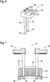
- FIG 4 shows an exemplary gripper finger 13, which serves to remove an individual substrate from the overall substrate 14.
- the gripper finger 13 has a holding section 27 at its free end, by means of which it can be guided through one of the cutouts in order to positively engage behind the respective individual substrate 16 and, after removal of the connecting webs, to lift it and thereby detach it from the overall substrate 14.
- the holding section 27 has a tapered diameter compared to the rest of the gripper finger 13, wherein the holding section is optionally coated with an advantageous material, in particular with a diamond coating, which prevents damage to the individual substrate and at the same time ensures secure holding of the individual substrate 16.
- the gripper 12 expediently has several such gripper fingers 13 in order to securely hold and transport the individual substrate 16.
- FIG. 5 shows a simplified sectional view of the transport device 9 in the area of the gripper receptacle 10.
- the gripper receptacle 10 has a recess, to which pneumatically displaceable locking elements 28 are assigned, which interact with the gripper 13.
- the gripper 13 has a locking pin 29, which can be inserted into the recess of the gripper receptacle 10 and is held there in a form-fitting manner by the locking elements 28.
- the locking pin 29 has a diameter taper 30, into which the locking elements 28 can be inserted in order to lock the gripper 12 in a form-fitting manner to the gripper receptacle 10.
- two of the gripper fingers 13 are held on the gripper 12.
- the separating device 1 has a further gripper 31, which is shown for example in Figures 6 and 7 will be explained in more detail.
- the gripper 31 has two gripper parts 32 which are of the same, in particular identical, design to one another. Both gripper parts 32 have a locking pin 33 which corresponds to the locking pin 29 in order to be able to be releasably locked in a respective recess of the gripper receptacle 10, as described above, by means of respective locking elements 28.
- two gripper fingers 34 are arranged on each gripper part 32.
- the gripper fingers 34 differ from the gripper fingers 13 in that their free ends do not have the holding section 27 formed thereon, but rather a gripper head 35 which is designed to interact positively with the brush 17, in particular with the carrier ring 21 of the brush 17.
- the respective gripper head 35 has a contour that at least substantially corresponds to the shape of the inside of the carrier ring 21.
- the respective gripper finger 34 with the gripper head 35 can thereby advantageously be placed, in particular flatly, on the inside of the carrier ring 21.
- the carrier ring 21 has, for example, a groove-shaped recess or, as in the present exemplary embodiment, a diameter extension or enlargement 36 extending over the circumference on its inside, wherein the diameter widens from the side of the carrier ring 21 facing away from the brush facing 22.
- the gripper has, as already mentioned above, two of the gripper parts 32. Both gripper parts 32 are in Figure 7 shown.
- the transport device 9 is designed to move the gripper parts 32 towards and away from each other, whereby the gripper heads 35 are moved into a release position and into a position engaging behind the carrier ring 21, as in Figure 7 shown, are displaceable. Because the gripper is moved by the spatial gantry robot 11, the gripper parts 32 can also be displaced in height in order to be inserted into or withdrawn from the brush 17, and to approach the brush magazine 25.
- the gripper receptacle 10 has two recesses, wherein one of the gripper parts 32 can be locked in each recess, as shown in Figure 5 shown as an example on a gripper part 31.
- the gripper fingers 13 are also advantageously held in pairs on gripper parts, each of which can be held and locked in one of the recesses of the gripper receptacle 10.
- the recesses are each formed in a receiving part of the gripper receptacle 10, wherein the receiving parts can be displaced relative to one another, in particular moved towards and away from one another, in order to perform the functions described above.
- This also allows the individual substrates 16 to be advantageously gripped and transported by means of the gripper fingers 13.
- the advantageous separating device 1 now has two types of grippers 31, 12, which are designed to be interchangeable and can thus be used selectively by the transport device 9, it is possible with the advantageous separating device 1 to transport both the individual substrates 16 and the brushes 17 and, in particular, to replace the brushes 17.
- the brush when wear of the brush 17 currently in use is detected, the brush is placed in a free storage location 26 of the magazine 25 by the transport device 9 and the gripper fingers 34 are inserted into an unused brush 17 held in another of the storage locations 26 of the brush magazine 25 in order to fasten it to the brush holder 38 of the suction device 18.
- the brush holder 38 has elastically pre-tensioned locking elements 37, as in Figure 3 shown by way of example, which cooperate with the carrier ring 21, in particular with its outer side, for its detachable fastening.
- the locking elements 37 are designed, for example, to be displaced outwards against a spring force when the carrier ring 21 is placed on the suction cup 20, in order to then engage behind the carrier ring at least in some areas when it springs back and thus lock into place.
- the brush 17 is positively locked to the suction cup 20 or to the brush holder 38.
- the respective locking element 37 is displaced radially outwards against the spring force in the same way, thereby advantageously releasing the brush 17 from the brush holder 38.
- the locking elements 37 advantageously have a locking ball or the like which interacts with the carrier ring 21 and causes the brush to be pushed back against the spring force when displaced.
- such locking elements 37 are also arranged at the storage locations 26 of the magazine 25 in order to enable the brushes 17 to be securely locked in the storage locations 26.
- the transport direction 9 is particularly designed to pneumatically displace both the locking elements 28 and the gripper parts 32. Accordingly, each gripper part 32 is assigned a pneumatic actuator or a common actuator, by means of which the gripper parts 32 and thus the gripper fingers 34 can be displaced relative to one another in order to engage behind or release a brush 17.
- the separating device 1 has a gripper magazine in which the different grippers 12 and 31 can be stored. This allows the transport device 9 to automatically exchange the gripper fingers or grippers 31, 12 without manual assistance.
- the separating device 1 is designed to perform the separation and replacement of the brush 17 fully automatically. This reduces downtime and increases the throughput of the separating device 1. At the same time, high processing quality is ensured.
Landscapes
- Engineering & Computer Science (AREA)
- Physics & Mathematics (AREA)
- Acoustics & Sound (AREA)
- Robotics (AREA)
- Mechanical Engineering (AREA)
- Manufacturing & Machinery (AREA)
- Microelectronics & Electronic Packaging (AREA)
- Manipulator (AREA)
Applications Claiming Priority (1)
| Application Number | Priority Date | Filing Date | Title |
|---|---|---|---|
| DE102023131352.5A DE102023131352A1 (de) | 2023-11-10 | 2023-11-10 | Vereinzelungseinrichtung für flächige Substrate |
Publications (1)
| Publication Number | Publication Date |
|---|---|
| EP4554343A1 true EP4554343A1 (fr) | 2025-05-14 |
Family
ID=93460512
Family Applications (1)
| Application Number | Title | Priority Date | Filing Date |
|---|---|---|---|
| EP24211617.6A Pending EP4554343A1 (fr) | 2023-11-10 | 2024-11-08 | Dispositif de séparation pour substrats plats |
Country Status (2)
| Country | Link |
|---|---|
| EP (1) | EP4554343A1 (fr) |
| DE (1) | DE102023131352A1 (fr) |
Citations (4)
| Publication number | Priority date | Publication date | Assignee | Title |
|---|---|---|---|---|
| EP0883980B1 (fr) * | 1996-02-26 | 2000-05-17 | PMJ Cencorp LLC | Appareil et procede pour separer rapidement des cartes d'un panneau a cartes de circuit imprime |
| US20170282318A1 (en) * | 2016-03-31 | 2017-10-05 | Mark P. Chepurny | Debris control apparatus for cutting machines |
| EP3797925A1 (fr) * | 2019-09-26 | 2021-03-31 | MSTECH Co., Ltd | Appareil de routage |
| WO2021150493A1 (fr) * | 2020-01-21 | 2021-07-29 | Linkdyn Robertics Inc. | Pince parallèle à longue course et à commande de force |
Family Cites Families (2)
| Publication number | Priority date | Publication date | Assignee | Title |
|---|---|---|---|---|
| US4909681A (en) * | 1986-09-30 | 1990-03-20 | Cybernetics Products, Inc. | Router for component mounted printed circuit boards |
| DE102018211278A1 (de) * | 2018-07-09 | 2020-01-09 | Frimo Group Gmbh | Absaugeinrichtung für Bearbeitungsvorrichtung |
-
2023
- 2023-11-10 DE DE102023131352.5A patent/DE102023131352A1/de active Pending
-
2024
- 2024-11-08 EP EP24211617.6A patent/EP4554343A1/fr active Pending
Patent Citations (4)
| Publication number | Priority date | Publication date | Assignee | Title |
|---|---|---|---|---|
| EP0883980B1 (fr) * | 1996-02-26 | 2000-05-17 | PMJ Cencorp LLC | Appareil et procede pour separer rapidement des cartes d'un panneau a cartes de circuit imprime |
| US20170282318A1 (en) * | 2016-03-31 | 2017-10-05 | Mark P. Chepurny | Debris control apparatus for cutting machines |
| EP3797925A1 (fr) * | 2019-09-26 | 2021-03-31 | MSTECH Co., Ltd | Appareil de routage |
| WO2021150493A1 (fr) * | 2020-01-21 | 2021-07-29 | Linkdyn Robertics Inc. | Pince parallèle à longue course et à commande de force |
Also Published As
| Publication number | Publication date |
|---|---|
| DE102023131352A1 (de) | 2025-05-15 |
Similar Documents
| Publication | Publication Date | Title |
|---|---|---|
| DE60318498T2 (de) | Roboter zur Behandlung von Behälter für biologische Proben | |
| EP0216261A2 (fr) | Machine-outil | |
| DE102017114728B3 (de) | Verfahren zum gegenseitigen Trennen zweier Werkstückteile eines plattenförmigen Materials sowie Greifeinrichtung für eine Handlingsvorrichtung und Handlingsvorrichtung einer Bearbeitungsmaschine | |
| EP4178758B1 (fr) | Dispositif de prehension convertible | |
| DE112010003696T5 (de) | Polierverfahren und Poliervorrichtung | |
| EP4351831B1 (fr) | Procédé et dispositif pour souder des lames | |
| WO2015169790A1 (fr) | Système de machine-outil et procédé pour faire fonctionner un système de machine-outil | |
| DE4305470A1 (de) | Verfahren und Vorrichtung zum automatischen Assemblieren und Bearbeiten von mehreren Bauteilen | |
| EP3482935B1 (fr) | Unité de tamisage pour un dispositif d'impression | |
| DE19858791A1 (de) | Plattenbearbeitungsmaschine | |
| DE102010061546A1 (de) | Vorrichtung und Verfahren zum Lösen von Elektrodenkappen | |
| EP4554343A1 (fr) | Dispositif de séparation pour substrats plats | |
| WO2020053187A1 (fr) | Dispositif comprenant un premier et un deuxième robot et son procédé de fonctionnement | |
| EP3362201B1 (fr) | Procédé de fonctionnement d'une presseur plieuse et presse plieuse | |
| EP1073599B1 (fr) | Procede et dispositif pour manipuler des substrats | |
| DE102018115042A1 (de) | Flächensauggreifer und Verfahren zur Entnahme von Formteilen aus einem Restgitter | |
| DE102016114854A1 (de) | Schleifvorrichtung | |
| DE102018219437A1 (de) | Stanzvorrichtung zur Erzeugung mehrerer Reihen von schlusslosen Teigringen | |
| WO1993022100A1 (fr) | Dispositif pour l'usinage de metaux par enlevement de copeaux | |
| EP1766419B1 (fr) | Dispositif d'isolement et de traitement automatique de clones de cellules | |
| EP3103582A2 (fr) | Machine d'usinage dotee d'un dispositif de transfert d'outil | |
| DE202008010060U1 (de) | Werkzeugwechselvorrichtung | |
| EP3614880B1 (fr) | Dispositif d'usinage de brosses à fixation par vissage | |
| DE202025105018U1 (de) | Transportmittel für Werkzeugaufnahmen | |
| WO1998015971A1 (fr) | Dispositif de prehension pour tranches |
Legal Events
| Date | Code | Title | Description |
|---|---|---|---|
| PUAI | Public reference made under article 153(3) epc to a published international application that has entered the european phase |
Free format text: ORIGINAL CODE: 0009012 |
|
| STAA | Information on the status of an ep patent application or granted ep patent |
Free format text: STATUS: THE APPLICATION HAS BEEN PUBLISHED |
|
| AK | Designated contracting states |
Kind code of ref document: A1 Designated state(s): AL AT BE BG CH CY CZ DE DK EE ES FI FR GB GR HR HU IE IS IT LI LT LU LV MC ME MK MT NL NO PL PT RO RS SE SI SK SM TR |
|
| STAA | Information on the status of an ep patent application or granted ep patent |
Free format text: STATUS: REQUEST FOR EXAMINATION WAS MADE |
|
| 17P | Request for examination filed |
Effective date: 20251114 |