EP0883980B1 - Appareil et procede pour separer rapidement des cartes d'un panneau a cartes de circuit imprime - Google Patents
Appareil et procede pour separer rapidement des cartes d'un panneau a cartes de circuit imprime Download PDFInfo
- Publication number
- EP0883980B1 EP0883980B1 EP97907920A EP97907920A EP0883980B1 EP 0883980 B1 EP0883980 B1 EP 0883980B1 EP 97907920 A EP97907920 A EP 97907920A EP 97907920 A EP97907920 A EP 97907920A EP 0883980 B1 EP0883980 B1 EP 0883980B1
- Authority
- EP
- European Patent Office
- Prior art keywords
- boards
- panel
- registration
- arm
- subsequent processing
- Prior art date
- Legal status (The legal status is an assumption and is not a legal conclusion. Google has not performed a legal analysis and makes no representation as to the accuracy of the status listed.)
- Expired - Lifetime
Links
Images


Classifications
-
- H—ELECTRICITY
- H05—ELECTRIC TECHNIQUES NOT OTHERWISE PROVIDED FOR
- H05K—PRINTED CIRCUITS; CASINGS OR CONSTRUCTIONAL DETAILS OF ELECTRIC APPARATUS; MANUFACTURE OF ASSEMBLAGES OF ELECTRICAL COMPONENTS
- H05K13/00—Apparatus or processes specially adapted for manufacturing or adjusting assemblages of electric components
- H05K13/0061—Tools for holding the circuit boards during processing; handling transport of printed circuit boards
-
- H—ELECTRICITY
- H05—ELECTRIC TECHNIQUES NOT OTHERWISE PROVIDED FOR
- H05K—PRINTED CIRCUITS; CASINGS OR CONSTRUCTIONAL DETAILS OF ELECTRIC APPARATUS; MANUFACTURE OF ASSEMBLAGES OF ELECTRICAL COMPONENTS
- H05K3/00—Apparatus or processes for manufacturing printed circuits
- H05K3/0011—Working of insulating substrates or insulating layers
- H05K3/0044—Mechanical working of the substrate, e.g. drilling or punching
- H05K3/0052—Depaneling, i.e. dividing a panel into circuit boards; Working of the edges of circuit boards
-
- H—ELECTRICITY
- H05—ELECTRIC TECHNIQUES NOT OTHERWISE PROVIDED FOR
- H05K—PRINTED CIRCUITS; CASINGS OR CONSTRUCTIONAL DETAILS OF ELECTRIC APPARATUS; MANUFACTURE OF ASSEMBLAGES OF ELECTRICAL COMPONENTS
- H05K1/00—Printed circuits
- H05K1/02—Details
- H05K1/0266—Marks, test patterns or identification means
-
- H—ELECTRICITY
- H05—ELECTRIC TECHNIQUES NOT OTHERWISE PROVIDED FOR
- H05K—PRINTED CIRCUITS; CASINGS OR CONSTRUCTIONAL DETAILS OF ELECTRIC APPARATUS; MANUFACTURE OF ASSEMBLAGES OF ELECTRICAL COMPONENTS
- H05K2201/00—Indexing scheme relating to printed circuits covered by H05K1/00
- H05K2201/09—Shape and layout
- H05K2201/09818—Shape or layout details not covered by a single group of H05K2201/09009 - H05K2201/09809
- H05K2201/09936—Marks, inscriptions, etc. for information
-
- H—ELECTRICITY
- H05—ELECTRIC TECHNIQUES NOT OTHERWISE PROVIDED FOR
- H05K—PRINTED CIRCUITS; CASINGS OR CONSTRUCTIONAL DETAILS OF ELECTRIC APPARATUS; MANUFACTURE OF ASSEMBLAGES OF ELECTRICAL COMPONENTS
- H05K2203/00—Indexing scheme relating to apparatus or processes for manufacturing printed circuits covered by H05K3/00
- H05K2203/02—Details related to mechanical or acoustic processing, e.g. drilling, punching, cutting, using ultrasound
- H05K2203/0228—Cutting, sawing, milling or shearing
-
- H—ELECTRICITY
- H05—ELECTRIC TECHNIQUES NOT OTHERWISE PROVIDED FOR
- H05K—PRINTED CIRCUITS; CASINGS OR CONSTRUCTIONAL DETAILS OF ELECTRIC APPARATUS; MANUFACTURE OF ASSEMBLAGES OF ELECTRICAL COMPONENTS
- H05K2203/00—Indexing scheme relating to apparatus or processes for manufacturing printed circuits covered by H05K3/00
- H05K2203/16—Inspection; Monitoring; Aligning
- H05K2203/163—Monitoring a manufacturing process
-
- H—ELECTRICITY
- H05—ELECTRIC TECHNIQUES NOT OTHERWISE PROVIDED FOR
- H05K—PRINTED CIRCUITS; CASINGS OR CONSTRUCTIONAL DETAILS OF ELECTRIC APPARATUS; MANUFACTURE OF ASSEMBLAGES OF ELECTRICAL COMPONENTS
- H05K2203/00—Indexing scheme relating to apparatus or processes for manufacturing printed circuits covered by H05K3/00
- H05K2203/16—Inspection; Monitoring; Aligning
- H05K2203/167—Using mechanical means for positioning, alignment or registration, e.g. using rod-in-hole alignment
-
- H—ELECTRICITY
- H05—ELECTRIC TECHNIQUES NOT OTHERWISE PROVIDED FOR
- H05K—PRINTED CIRCUITS; CASINGS OR CONSTRUCTIONAL DETAILS OF ELECTRIC APPARATUS; MANUFACTURE OF ASSEMBLAGES OF ELECTRICAL COMPONENTS
- H05K3/00—Apparatus or processes for manufacturing printed circuits
- H05K3/0008—Apparatus or processes for manufacturing printed circuits for aligning or positioning of tools relative to the circuit board
-
- Y—GENERAL TAGGING OF NEW TECHNOLOGICAL DEVELOPMENTS; GENERAL TAGGING OF CROSS-SECTIONAL TECHNOLOGIES SPANNING OVER SEVERAL SECTIONS OF THE IPC; TECHNICAL SUBJECTS COVERED BY FORMER USPC CROSS-REFERENCE ART COLLECTIONS [XRACs] AND DIGESTS
- Y10—TECHNICAL SUBJECTS COVERED BY FORMER USPC
- Y10T—TECHNICAL SUBJECTS COVERED BY FORMER US CLASSIFICATION
- Y10T29/00—Metal working
- Y10T29/51—Plural diverse manufacturing apparatus including means for metal shaping or assembling
- Y10T29/5147—Plural diverse manufacturing apparatus including means for metal shaping or assembling including composite tool
- Y10T29/5148—Plural diverse manufacturing apparatus including means for metal shaping or assembling including composite tool including severing means
-
- Y—GENERAL TAGGING OF NEW TECHNOLOGICAL DEVELOPMENTS; GENERAL TAGGING OF CROSS-SECTIONAL TECHNOLOGIES SPANNING OVER SEVERAL SECTIONS OF THE IPC; TECHNICAL SUBJECTS COVERED BY FORMER USPC CROSS-REFERENCE ART COLLECTIONS [XRACs] AND DIGESTS
- Y10—TECHNICAL SUBJECTS COVERED BY FORMER USPC
- Y10T—TECHNICAL SUBJECTS COVERED BY FORMER US CLASSIFICATION
- Y10T29/00—Metal working
- Y10T29/51—Plural diverse manufacturing apparatus including means for metal shaping or assembling
- Y10T29/5196—Multiple station with conveyor
-
- Y—GENERAL TAGGING OF NEW TECHNOLOGICAL DEVELOPMENTS; GENERAL TAGGING OF CROSS-SECTIONAL TECHNOLOGIES SPANNING OVER SEVERAL SECTIONS OF THE IPC; TECHNICAL SUBJECTS COVERED BY FORMER USPC CROSS-REFERENCE ART COLLECTIONS [XRACs] AND DIGESTS
- Y10—TECHNICAL SUBJECTS COVERED BY FORMER USPC
- Y10T—TECHNICAL SUBJECTS COVERED BY FORMER US CLASSIFICATION
- Y10T409/00—Gear cutting, milling, or planing
- Y10T409/30—Milling
- Y10T409/303752—Process
- Y10T409/303808—Process including infeeding
-
- Y—GENERAL TAGGING OF NEW TECHNOLOGICAL DEVELOPMENTS; GENERAL TAGGING OF CROSS-SECTIONAL TECHNOLOGIES SPANNING OVER SEVERAL SECTIONS OF THE IPC; TECHNICAL SUBJECTS COVERED BY FORMER USPC CROSS-REFERENCE ART COLLECTIONS [XRACs] AND DIGESTS
- Y10—TECHNICAL SUBJECTS COVERED BY FORMER USPC
- Y10T—TECHNICAL SUBJECTS COVERED BY FORMER US CLASSIFICATION
- Y10T409/00—Gear cutting, milling, or planing
- Y10T409/30—Milling
- Y10T409/304536—Milling including means to infeed work to cutter
- Y10T409/305544—Milling including means to infeed work to cutter with work holder
- Y10T409/3056—Milling including means to infeed work to cutter with work holder and means to selectively position work
-
- Y—GENERAL TAGGING OF NEW TECHNOLOGICAL DEVELOPMENTS; GENERAL TAGGING OF CROSS-SECTIONAL TECHNOLOGIES SPANNING OVER SEVERAL SECTIONS OF THE IPC; TECHNICAL SUBJECTS COVERED BY FORMER USPC CROSS-REFERENCE ART COLLECTIONS [XRACs] AND DIGESTS
- Y10—TECHNICAL SUBJECTS COVERED BY FORMER USPC
- Y10T—TECHNICAL SUBJECTS COVERED BY FORMER US CLASSIFICATION
- Y10T409/00—Gear cutting, milling, or planing
- Y10T409/30—Milling
- Y10T409/306048—Milling with means to advance work or product
Definitions
- the invention relates to the field of handling multi-board panels containing an array of printed circuit (PC) boards with machinery adapted to depanel or liberate each PC board from the panel.
- the invention comprises depaneling machinery which embodies an in-line process in which individual boards are quickly depaneled and delivered to a registration nest. The boards are delivered from the registration nest for subsequent processing by the other automated equipment while the next panel of boards is depaneled.
- PC board assembly involves the insertion and attachment of various electrical components to the PC board by automatic means.
- a common approach is to assemble multiple PC boards at one time by employing a panel which comprises a plurality of PC boards, such as three. In this way, multiple PC boards are assembled while only a single panel need by handled by the automated assembly equipment.
- This approach simplifies and speeds up the assembly operation.
- a critical step in this process is removing the individual PC boards from the panel so they can be further processed or assembled into finished goods such as televisions or other electronic equipment. This operation is referred to as "depaneling" or “liberating" the boards from the panel.
- the depaneling process must be accomplished with sufficient speed to satisfy the needs of the overall assembly process and must be done in such a way that the electronic components connected to the boards are not damaged.
- the manufacture of electronics based goods becomes more automated, it is common to integrate the PC board depaneling and assembly process into the overall manufacturing line of which the PC boards are a part.
- the telephone assembly line rather than a telephone manufacturing process drawing from an inventory of preassembled PC boards, it is common for the telephone assembly line to include a PC board assembly process where, at a point in the process, the just-assembled PC board is inserted into a telephone housing.
- This has increased the need for PC board assembly equipment, and in particular depaneling equipment, that can maintain a known registration of the depaneled PC boards so that subsequent automated equipment can be programmed to accept the liberated PC boards from a known location and continue the manufacturing process.
- the routing head depanels all the PC boards from a panel.
- the depaneled PC boards are then moved concurrently by a movable arm from the table to a conveyor belt or some other unregistered location at a subsequent processing location.
- each PC board is cut, sequentially, one at a time from the panel.
- Each individual PC board is then moved by the movable arm from the table to a conveyer belt or a registered location at a subsequent processing location.
- a registered location is a location that holds a PC board in a known, programmable position.
- the debris of the depaneling process is transferred by conveyer belt from the depaneling machine.
- the apparatus described by Carr is effective for its intended purpose but it is less than ideal in some important respects, especially considering the increased requirements for today's electronics assembly processes.
- the Carr patent makes no provision for transferring multiple, depaneled PC boards to subsequent automated equipment without slowing the depaneling process.
- the movable arm described by Carr performs the functions of supporting a panel while the router head operates to cut a PC board from the panel, moving one or more PC boards from the table after depaneling, and moving one or more boards to a subsequent processing station. This means that while the arm described by Carr is occupied with transferring one or more depaneled PC boards to a subsequent processing station, the depaneling process is stopped because the same arm is needed to support the panel during the depaneling process. Therefore, the depaneling process of Carr is idle until the depaneled PC boards are delivered, either concurrently or one at a time, to a subsequent processing station.
- Another disadvantage of the Carr invention is the relatively slow speed of his routing process.
- the router head described by Carr moves only in one axis. Therefore his table must also move in order to accomplish the necessary cuts in a panel to depanel the PC boards. This movement by the table in the Carr invention adds time to the depaneling process.
- the depaneling machinery described by Carr is also made more complex due to the need to provide servo control of the table.
- a further problem with the Carr depaneling equipment is the lack of a flexible and cost-efficient apparatus for verifying certain characteristics of the PC boards to be depaneled.
- a PC board comprising part of a panel may have been deemed unfit for use at a processing station prior to the depaneling operation and may have been marked as a "bad” board.
- the depaneling equipment of Carr provides no apparatus for recognizing and processing such "bad" boards.
- depaneling equipment that depanels PC boards and controllably arranges the depaneled boards in known, programmable, locations for pick-up by other automated equipment comprising the next step in an industrial process.
- depaneling machine that performs the depaneling operation quickly while achieving the necessary registration of the PC boards for subsequent automated equipment and which disposes of the debris of the depaneling process by removing it from the process line without adding additional time to the machine's through-put time.
- board verification system that is flexible and cost-efficient.
- the present invention solves the above identified problems and advances the state of the useful arts by providing apparatus and methods for depaneling PC boards from a panel comprised of an array of PC boards.
- this invention is embodied by a depaneling machine having a high through-put which, after depaneling the PC boards, positions the PC boards in known, programmable locations. All of this is accomplished, as well as the disposal of debris, without increasing the through-put time of the depaneling machine.
- the present invention provides a seamless transition in an electronics manufacturing process between handling multiple PC boards at one time in a panel and handling each PC board as an individual unit.
- apparatus embodying the present invention includes a depaneler system which cuts all the PC boards from the panel and which maintains a complete 3 axis registration of the depaneled PC boards.
- the plurality of PC boards cut from the panel are moved concurrently to a registration "nest" in which the PC boards are placed.
- the registration nest is associated with a registration arm for moving depaneled PC boards, one at a time, to the next station in the assembly process while maintaining 3 axis registration between the PC board and the registration arm.
- the movable arm of the prior art performed multiple functions, two arms are provided in the present invention to better optimize the performance of the depaneler system.
- a depaneler arm supports the PC boards in a panel while the PC boards are cut from the panel.
- the depaneler arm transports all the PC boards concurrently from the table, after the routing process, to the registration nest.
- a registration arm then picks up the PC boards, one at a time, and delivers each PC board, one at a time, to a subsequent processing station.
- the registration nest of the present invention provides a platform, or nest, on which all depaneled PC boards of a panel board are concurrently placed after being depaneled from the panel.
- a registration arm picks up each PC board, one at a time, from the registration nest and moves the PC board to a subsequent processing station.
- the registration arm can transport the board directly to a location for final assembly of a product and, for example, it can insert the board into a telephone housing piece.
- the depaneler system operates more efficiently since the depaneled PC boards are held in the registration nest while the depaneler arm returns to the table to begin processing on a new panel While a new panel is being routed, the registration arm delivers PC boards, one at a time, to a subsequent processing station.
- a fixed table of the present invention solves an additional problem of the prior art.
- the depaneler arm fingers move into position over the PC boards in the panel. The fingers grasp each individual PC board.
- each board is concurrently held by a set of fingers.
- the panel material that held the individual PC boards together is now debris.
- this debris was handled in various ways. One way was to carry the debris to another location using a conveyer system. This, of course, adds cost and complexity to the depaneler. Another way was to make additional cuts in the debris so that the debris could drop through an opening in the table. This adds time to the process as the router cannot operate on a new panel when it is making cuts in the debris of the previous panel.
- a rail comprising one side of the table is moved to effectively widen the table and cause the debris to drop through a table opening into a waste bin. This operation adds no time to the depaneling process and effectively removes the debris from the work area.
- a further advantage of the present invention relates to a board verification system.
- an optical sensor is attached to the router head assembly and positioned to detect information encoded onto the panel or on a PC board.
- the router head can be programmed to move to a position to read markings or holes placed on the panel to verify proper orientation or alignment of the panel.
- the depaneler system can adjust its operation based on the information read by the board verification system. For example, prior to the panel reaching the depaneler system, a PC board within a panel may fail a certain test. As a result, the PC board is marked, in a prior process, by having a hole punched through the PC board at a certain location.
- the verification system of the present invention identifies the failed PC board by sensing the hole in the PC board.
- the depaneler system then does not process the failed PC board but rather allows the failed PC board to be scrapped along with the debris of the depaneling process.
- Other uses of the verification system include providing a fault signal in the event a panel becomes misaligned in the process or, for example, is upside down.
- a further advantage of the board verification system is to detect different types of boards.
- An electronic assembly process may be arranged to process more than one type of board sequentially. In this event, the optic verification system can differentiate between different types of panels as they enter the depaneler and load the appropriate routing program for that type of board to direct the router head.
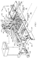
- FIG. 1 is a perspective view of the depaneling system of the invention.
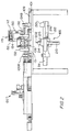
- FIG. 2 depicts a side view of the depaneling system of FIG. 1.
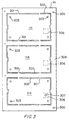
- FIG. 3 depicts a panel having interconnected PC boards.
- FIG. 4 is a perspective view of the staging area of the depaneling system of FIG 1.
- FIG. 5 is a perspective view of the depaneling system of FIG. 1 excluding the registration arm assembly.
- FIG. 6 is a perspective view of the registration area and registration arm assembly of the depaneling system.
- Figures 1,2,4,5 and 6 depict various views of a depaneler system 100.
- a description of a panel 111, with respect to Figure 3 is first provided.
- Panel 111 containing 3 PC boards 114 is depicted in Figure 3.
- Slots 302 and tabs 301 define the edges of PC boards 114.
- Tabs 301 connect each PC board 114 to panel 111 and are cut during the depaneling process to release each PC board 114 from panel 111.
- Registration holes 303 are positioned to mesh with registration nest 205 as described in more detail below.
- Holes 305 are arranged to mate with tapered pins 171 of positioning assemblies 132 when panel 111 is held in rails 131 and 130, all as described with respect to FIG. 1.
- Frame 304 is the material of panel 111 that holds each PC board 114 together as a single panel 111. Frame 304 becomes the debris of the depaneling process, as described in more detail below.
- panel 111 may be comprised of any number of PC boards 114. Panel 111 may not have slots 302 pre-cut as shown in Figure 3 or may have smaller slots 302 and larger tabs 301.
- a panel 111 of interconnected PC boards 114 first enters depaneling system 100 at a staging area 190, shown in Figure 4.
- panel 111 is moved from staging area 190 to a depaneling area 191 and held at the position shown in Figure 1.
- a router assembly 185 described in more detail with respect to Figure 2, cuts PC boards 114 from panel 111.
- a depaneler arm assembly 119 moves the depaneled PC boards 114 concurrently from depaneling area 191 to a registration area 192. From registration area 192, a registration arm assembly 120 moves PC boards 114 one at a time to a subsequent processing station (not shown in Figure 1).
- a controller 121 communicates with various motors and sensors, as described below, to coordinate the operations of depaneler system 100.
- controller 121 provides diagnostic status information and provides for on-line programming of depaneler system 100.
- Controller 121 may be an IBM compatible personal computer or similar device. All of the individual connections between controller 121 and the various motors and sensors of depaneler system 100 are not shown as this simplifies the figures. The nature of these connections is understood by those skilled in the art.
- staging rails 104 and 109 are attached to table 101 and are spaced apart to hold panel 111.
- Panel 111 is presented to staging rails 104 and 109, as shown in figure 4, from a previous processing step (not shown).
- Panel 111 is moved along staging rails 104 and 109 by conveyors 110.
- Staging rail 104 and staging rail 109 are each formed with a groove along the edge of the staging rail coincident with the edges of panel 111. Within that groove in each staging rail 104 and 109 is conveyer 110.
- the conveyor 110 associated with staging rail 109 cannot be seen in Figure 4.
- conveyor 110 is a continuous plastic or elastic O-ring which circulates around staging rail 104.
- Conveyor motor 124a causes conveyor 110 to circulate counterclockwise around the longitudinal axis of staging rail 104. Staging rails 104 and 109 are spaced apart so that conveyors 110 contact panel 111 and to move it in the direction indicated by the arrow in Figure 4. Conveyor motor 124b drives a similar conveyor 110 associated with staging rail 109. Conveyor motors 124a and 124b operate in response to signals from controller 121 and, depending on the signals from controller 121, can move conveyors 110 in either direction.
- Conveyor motors 124a-b drive conveyors 110 to move panel 111 from an entry position, shown in Figure 4, at one side of depaneler table 101 along staging rails 104 and 109 until panel 111's presence is detected by staging detector 125.
- Figure 5 depicts panel 111 engaged by staging rails 104 and 109 and moving towards staging detector 125.
- Staging detector 125 is a proximity detector that senses the presence of panel 111.
- Staging detector 125 communicates a signal to controller 121 when panel 111 is moved to a position in staging rails 104 and 109 adjacent to staging detector 125.
- Controller 121 responsive to a signal from staging detector 125, sends a signal to conveyor motors 124a-b to cause conveyor motors 124a-b to stop. In this way, conveyors 110 stop moving when panel 111 reaches a position along staging rails 104 and 109 adjacent to staging detector 125.
- panel 111 is held in staging area 190 until controller 121 communicates signals to move panel 111 from staging area 190 into depaneling area 191.
- Depaneler rails 130 and 131 are spaced apart similarly to staging rails 104 and 109 in order to accept panel 111 from staging area 190.
- Depaneler rail 130 and 131 are formed in similar fashion to staging rails 104 and 109 in that each has a groove formed on its surface coincident with panel 111. In the groove is conveyor 129 which is a continuous rubber or elastic O-ring. Conveyors 129 are caused to move by the operation of conveyor motor 126a associated with depaneler rail 130 and conveyor motor 126b associated with depaneler rail 131.
- controller 121 communicates signals to conveyor motors 124a and 124b to cause conveyors 110 to operate.
- the operation of conveyors 110 causes panel 111 to be moved from staging area 190 towards rails 130 and 131 in depaneling area 191.
- controller 121 communicates signals to conveyor motors 126a-b to cause conveyors 129 to move along depaneler rails 130 and 131.
- the motion of conveyors 110 moves panel 111 from staging area 190 into contract with conveyors 129.
- Conveyors 129 move panel 111 from the staging area to depaneling area 191.
- conveyors 129 moves panel 111 along depaneler rails 130 and 131 until panel 111 contacts panel stop element 127.
- Detector 528 shown in Figure 5 adjacent stop element 127 senses the presence of panel 111 and sends a signal to controller 121.
- Controller 121 responsive to a signal from detector 528, sends signals to motors 126a-b to stop conveyors 129.
- Panel 111 is now in the position shown in Figure 1.
- controller 121 communicates signals to a pair of positioning assemblies 132.
- Each positioning assembly 132 has a bar 170 and tapered pin 171. Signals from controller 121 cause pneumatic cylinders (not shown) in positioning assemblies 132 to lower bars 170 down toward panel 111.
- Tapered pins 171 mate with holes 305 in panel 111 to hold panel 111 in a fixed position. Whereas stop element 127 positions panel 111 relatively close to the desired location with respect to the X-Y axes, tapered pins 171 precisely position panel 111 for the routing process.
- Rails 130 and 131 have associated with them rail clamps 138 and 139, respectively. Referring to rail 130, rail clamp 138 rests on top of rail 130. In response to signals from controller 121, pneumatic cylinders (not shown) between rail 130 and rail clamp 138 cause rail clamp 138 to move downward clamping panel 111 between rail clamp 138 and rail 130. Operation of rail clamp 139 and with respect to rail 131 and panel 111 is similarly described.
- Depaneler arm assembly 119 comprises depaneler arm tower 112, depaneler arm support 150, and depaneler arm 105.
- Depaneler arm 105 is connected to depaneler arm support 150 by bolts 113. Precise positioning of depaneler arm 105 with respect to depaneler arm support 150 is established with locating pins (not shown) on depaneler arm support 150 which mate with holes (not shown) on depaneler arm 105.
- Bolts 113 are provided so that a user can process panels 111 of different designs by removing depaneler arm 105 and replacing it with depaneler arm 105 having a different configuration.
- Depaneler arm support 150 is slidably connected to depaneler tower 112 through guides 152.
- pneumatic cylinder 134 (Fig. 2) moves depaneler arm support 150 in the Z axis.
- Depaneler arm support 150 moves up and down along guides 152 as pneumatic cylinder 134 operates in response to signals from controller 121.
- Depaneler fingers 106 are connected to depaneler arm 105.
- a solenoid (not shown) operates, in response to signals from controller 121 to cause each pair of fingers 106 to grasp PC board 114.
- Depaneler tower 112 has base 153 which is slidably connected to guide 107.
- Depaneler arm assembly 119 moves in the X axis, along guide 107, by the operation of motor 133 and lead screw 123.
- Lead screw 123 is connected to motor 133 so that when motor 133 operates, lead screw 123 is turned.
- Lead screw 123 cooperates with base 153 of depaneler tower 112 such that when lead screw 123 is turned by motor 133, depaneler tower 112 is caused to move in the X axis along guide 107.
- the process of routing PC boards 114 from panel 111 is initiated after panel 111 is held in tracks 130 and 131 by rail clamps 138 and 139 and supported from above by fingers 106.
- Fingers 106 support panel 111 when controller 121 sends signals to drive motor 133. Operation of motor 133 causes depaneler arm assembly 119 to move along guide 107 so that fingers 106 are directly above panel 111. Signals communicated from controller 121 to pneumatic cylinder 134 cause depaneler arm 105 to move downward until depaneler fingers 106 are inserted into slots 302 in panel 111. Controller 121 sends signals to the solenoids for each pair of fingers 106 to cause fingers 106 to close and grasp panel 111. This is the state of depaneler system 100 shown in Figure 1.
- router assembly 185 is mounted below table 101.
- Depaneler arm assembly 119 and registration arm assembly 120 are positioned on top of table 101.
- Router assembly 185 can move in all three axes.
- Pneumatic cylinder 210 operates, in response to signals from controller 121, to cause router head 215 to move up and down in the Z axis.
- a motor 211 receives signals from controller 121 and, in response, drives lead screw 212 to cause router head 215 to move in the X direction.
- Motor 211, lead screw 212 and router head 215 are mounted on frame 216.
- Motor 213 is connected to a lead screw (not shown) to move frame 216, and router head 215, in the Y direction in response to signals from controller 121.
- Controller 121 sends signals to motors 211 and 213 to position router head 215 for the routing process.
- Pneumatic cylinder 210 in response to signals from controller 121, moves router head 215 upward in the Z axis so that router bit 202 engages panel 111 through one of slots 302 in panel 111.
- Router head 215 is moved in a programmed pattern, responsive to signals from controller 121 as just described, to cut each of tabs 301 which connect PC boards 114 to panel 111.
- panel 111 may instead have no slots 302.
- router bit 202 in response to signals from controller 121, must drill a hole in panel 111 in order to rout a slot 302 to depanel PC boards 114 from panel 111.
- controller 121 sends signals to operate pneumatic cylinder 134 in order to raise depaneler arm 105.
- Individual PC boards 114, grasped by fingers 106, are thereby lifted as a group from rails 130 and 131.
- Controller 121 sends signals to motor 133 to drive lead screw 123 and cause depaneler arm assembly 119 to move in the X direction towards the registration area 192 of depaneling system 100.
- Controller 121 then sends signals to release panel 111 by releasing rail clamps 138 and 139 and to raise tapered pins 171 from panel 111.
- Frame 304 of panel 111 is still resting in rails 130 and 131. Frame 304 is no longer needed and, through the following operation of depaneler system 100 described with reference to Figure 5, is removed from the process.
- Panel frame 304 is comprised of what is left of panel 111 when tabs 301 have been cut and PC boards 114 removed from panel 111.
- Solenoids (not shown), connected to rail 130 and depaneler table 101, receive signals from controller 121 to cause rail 130 to move slightly in the Y axis away from rail 131. Controller 121 sends signals to the solenoids to cause this Y axis movement of rail 130 after PC boards have been lifted as a group by depaneler arm 105.
- the depaneled PC boards 114 are held by fingers 106 of depaneler arm assembly 119 as depaneler arm assembly 119 transports PC boards 114 to place them in registration nest 140 as described below.
- Another panel 111 is presently in staging area 190 between rails 104 and 109.
- controller 121 sends signals to motors 124a-b and 126a-b to bring panel 111 of Figure 5 from staging rails 104 and 109 to rails 130 and 131.
- Registration nest 140 is described with reference to Figure 6.
- Registration nest 140 has base 601 which is removably attached to table 101 through pins 604.
- Compartments 602 are formed so that each compartment 602 receives one PC board 114.
- Each compartment has locator pins 603 which mate with holes 303 in PC boards 114 (shown in Figure 3).
- Registration nest 140 is uniquely configured for each different application of depaneler system 100 and is therefore provided with pins 604 to allow various different configurations of registration nest 140 to be attached to table 101 for various different applications.
- An example of a different configuration for panel 111 is a panel 111 containing 4 PC boards rather than 3 PC boards.
- Depaneler arm assembly 119 is moved along guide 107, in response to signals from controller 121 to motor 133 as described above, until PC boards 114 are positioned over registration nest 140. Controller 121 sends signals to pneumatic cylinder 134 causing depaneler arm 105 to move downward in the Z axis. Depaneler arm 105 is lowered until individual PC boards 114 contact their respective compartments in registration nest 140. As described above, locator pins 603 mate with holes 303 in PC boards 114 to precisely hold PC boards in registration nest 140. A sensor (not shown) in registration nest 140 sends a signal to controller 121 indicating the receipt of PC boards 114 by registration nest 140.
- Controller 121 sends a signal to the solenoids associated with fingers 106 to cause fingers 106 to release PC boards 114.
- PC boards 114 are now located in registration nest 140.
- Controller 121 sends signals to motor 133 to cause lead screw 123 to move depaneler assembly 119 back towards depaneling area 191 to begin operation on a second panel 111.
- Registration arm assembly 120 Operation of registration arm assembly 120 is described with respect to Figure 6. PC boards 114 are now ready to be delivered one at a time from registration nest 140 to subsequent processing station 610.
- Registration arm assembly 120 comprises frame 115 which spans from track 117 to guide 135.
- Frame 115 is slidably mounted on track 117 and engages lead screw 146, as described below, which extends within guide 135 along the X axis.
- Registration arm support 137 is slidably connected to frame 115 and moves in the Y direction along frame 115 by the operation of motor 147 and lead screw 148.
- Motor 147 operates in response to signals from controller 121 to turn lead screw 148.
- Lead screw 148 engages registration arm support 137 so that registration arm support 137 is moved along frame 115 by the turning of lead screw 148.
- Frame 115 is moved in the X axis by the operation of motor 145 and lead screw 146.
- Motor 145 operates in response to signals from controller 121 to turn lead screw 146.
- Lead screw 146 moves frame 115 to move along guide 135 and track 117 in the X direction.
- a registration arm 607 moves in the Z axis when pneumatic cylinder 605, in response to signals from controller 121, moves registration arm 607 to move up and down on guides 606.
- Guides 606 are connected to registration arm support 137 and registration arm 607 is slidably connected to guides 606.
- Controller 121 delivers signals as just described to move frame 115 along the X axis and to move registration arm support 137 in the Y axis. In this way, registration fingers 608 may be positioned over one of PC boards 114 in registration nest 140.
- pneumatic cylinder 605 lowers registration arm 607 so that registration fingers 608 are positioned around one of PC boards 114 located in registration nest 140.
- Registration fingers 608 are closed by a solenoid (not shown) in response to signals from controller 121 to cause registration fingers 608 to grasp a single PC board 114.
- Pneumatic cylinder 605 responds to signals from controller 121 to lift registration arm 607 thereby lifting single PC board 114 from registration nest 140.
- Registration arm 607 is a rotary actuator operable to rotate a PC board 114 by as much as 180 degrees. It is apparent to those skilled in the art that registration arm 607 can be articulated so that, when grasped by registration fingers 608 and lifted from registration nest 140, PC board 114 can be rotated, turned on an edge so that the plane of PC board 114 is orthogonal to the plane of registration table 203, or even turned upside down. Articulation of registration arm 607 is accomplished through use of one or more motors (not shown) and/or pneumatic cylinders (not shown). Controller 121 sends signals to motors 145 and 147 in order to position the grasped PC board 114 in the X and Y axes. This is the state of depaneler system 100 depicted in Figure 6.
- Controller 121 sends signals to the solenoid associated with registration fingers 608 to cause fingers 608 to open and release PC board 114 at subsequent processing station 610. Controller 121 communicates signals, as just described, to cause the remaining PC boards 114 in registration nest 140 to be moved from registration nest 140 to subsequent processing station 610.
- Subsequent processing station 610 has location 609. Location 609 may be a registered, known location with respect to the X, Y, and Z axes, as is depicted in Figure 6, or it may be simply a moving conveyor belt or other unregistered location.
- depaneler arm assembly 119 delivers a new set of depaneled PC boards 114 to registration nest 140.
- An optical sensor 214 is attached to router head assembly 215.
- Optical sensor 214 is used, when panel 111 is fixed between rails 130 and 131, to read the presence or absence of openings, markings, holes or other features on panel 111.
- a location on panel 111 can be checked by optical sensor 214 to ensure that panel 111 is in the proper orientation.
- a location on panel 111 or PC board 114 is selected so that. if panel 111 is in the proper orientation, it presents a particular feature, such as a hole, to optical sensor 214.
- controller 121 Prior to initiation of the routing process, controller 121 sends signals to motors 211 and 213 to position optical sensor 214 to read the appropriate location on panel 111.
- optical sensor 214 should sense a hole at the location on panel 111 if the board is properly oriented, but instead does not sense a hole, optical sensor 214 indicates to controller 121 that panel 111 is not in the proper orientation. The operation of depaneler system 100 can then be halted and a warning signal generated by controller 121 to alert the operator of a problem.
- optical sensor 214 Another use of optical sensor 214 is to allow the automatic processing of different types of panels 111 on depaneler system 100.
- a type A of panel 111 is marked with a hole punched at a certain location.
- a type B of panel 111 is marked with no hole punched at the same certain location.
- optical sensor 214 is moved, responsive to signals from controller 121, to be immediately below the certain location on panel 111. If a type A board is sensed, i.e., a hole at the certain location, by optical sensor 214, then a first routing program is loaded by controller 121.
- a second routing program is loaded by controller 121.
- the routing process is completed by signals from controller 121 using either the first routing program, if a Type A panel is in place, or the second routing program, if a Type B panel is in place. This allows for a great deal of flexibility in operation of depaneler system 100.
- optical sensor 214 is to screen out "bad" PC boards. If, during processing at a previous processing station (not shown) a PC board 114 within a panel is found to be defective, a hole is punched in a known location 306, shown in Figure 3. When panel 111 is fixed between rails 130 and 131, and before the routing operation begins, router head 215 is moved to place optical sensor 214 immediately below each location 306 on each PC board 114. If no hole has been punched at location 306, the light of optical sensor 214 is reflected back to optical sensor 214 to generate, for example, a "good" signal which is communicated to controller 121.
- a hole has been punched at location 306, such as hole 307 in PC board 114 depicted in Figure 3, the light of optical sensor 214 is not reflected to optical sensor 214 and a "bad" signal is generated by optical sensor 214 and sent to controller 121.
- controller 121 communicates signals to router assembly 201 to cause router assembly 201 to skip the routing of PC boards 114 which were indicated to be "bad” by optical sensor 214.
- the "bad" PC board 114 is not separated from panel frame 304 and is, therefore, dropped into waste bin 501 after the completion of the routing process. In this way, depaneler system 100 can adjust its operation based on the information read by optical sensor 214.
- Location 306 on PC board 114 can be anywhere on PC board 114 or on frame 304. Since optical sensor 214 is mounted on router head 215, optical sensor 214 can be moved to sense any location on panel 111. Positions on panel 111 can be marked similarly to locations 306 on PC boards 114.
Landscapes
- Engineering & Computer Science (AREA)
- Manufacturing & Machinery (AREA)
- Microelectronics & Electronic Packaging (AREA)
- Automatic Assembly (AREA)
- Supply And Installment Of Electrical Components (AREA)
Abstract
Claims (19)
- Appareil (100) de séparation de cartes d'un panneau, pour traiter un panneau (111) doté d'un réseau de cartes à circuit imprimé (114), comprenant :ledit appareil de séparation de cartes d'un panneau étant caractérisé parune table (101) pour recevoir ledit panneau;un moyen (127, 130, 131) pour positionner ledit panneau dans une position prédéterminée (191) sur ladite table;un moyen d'acheminement (185) déplaçable par commande, pour couper chacune desdites cartes à circuit imprimé dudit panneau;un moyen de repérage (140);un moyen pour déplacer (119) simultanément chacune desdites cartes à circuit imprimé de ladite position prédéterminée sur la table audit moyen de repérage, lesdites cartes à circuit imprimé étant maintenues en un emplacement connu (192) par rapport audit moyen de repérage; etun moyen pour fournir (120) par commande chacune desdites cartes à circuit imprimé, une à la fois, dudit moyen de repérage à un poste de traitement subséquent.
- Appareil selon la revendication 1, dans lequel ledit moyen pour déplacer simultanément chacune desdites cartes à circuit imprimé de ladite position prédéterminée sur la table audit moyen de repérage, comprend :un bras (105) de séparation de cartes d'un panneau actionnable pour se déplacer selon au moins deux axes; etun moyen (106) dudit bras de séparation de cartes d'un panneau pour supporter lesdites cartes à circuit imprimé lorsque lesdites cartes à circuit imprimé sont retirées dudit panneau et pour maintenir le repérage entre lesdites cartes à circuit imprimé et ledit bras de séparation de cartes d'un panneau lorsque ledit bras de séparation de cartes d'un panneau déplace lesdites cartes à circuit imprimé jusqu'audit moyen de repérage.
- Appareil selon la revendication 2, dans lequel différentes cartes parmi lesdites cartes à circuit imprimé présentent des détails physiques différents, ledit bras de séparation de cartes d'un panneau comprenant en outre :
un moyen de configuration (106) fixé audit bras de séparation de cartes d'un panneau, ledit moyen de configuration étant interchangeable avec un deuxième moyen de configuration dans le but de s'adapter auxdits détails différents et donc de supporter des cartes différentes parmi lesdites cartes à circuit imprimé. - Appareil selon la revendication 1, dans lequel ledit moyen pour fournir par commande chacune desdites cartes à circuit imprimé, une à la fois, dudit moyen de repérage audit poste de traitement subséquent, comprend:un bras de repérage (607);un moyen pour saisir (608) l'une desdites cartes à circuit imprimé à l'aide dudit bras de repérage; etun moyen pour commander (121) ledit bras de repérage en vue de transporter lesdites cartes à circuit imprimé, une à la fois, jusqu'audit poste de traitement subséquent.
- Appareil selon la revendication 4, dans lequel des cartes différentes parmi lesdites cartes à circuit imprimé présentent des détails physiques différents, ledit bras de repérage comprenant en outre :
un moyen de configuration (608) fixé audit bras de repérage, ledit moyen de configuration étant interchangeable avec un deuxième moyen de configuration dans le but de s'adapter auxdits détails différents et donc de supporter lesdites différentes cartes à circuit imprimé. - Appareil selon la revendication 4, dans lequel ledit bras de repérage comprend :
un moyen pour déplacer (145) (147) (605) ledit bras de repérage selon trois axes, ou plus, pour établir un repérage avec chacune desdites cartes à circuit imprimé par rapport audit bras de repérage et déplacer chacune desdites cartes à circuit imprimé, une à la fois, jusqu'audit poste de traitement subséquent. - Appareil selon la revendication 4, dans lequel ledit moyen de commande pour ledit bras de repérage comprend :un moyen de sélection (121) pour sélectionner l'un desdits postes de traitement subséquents parmi un groupe d'au moins deux desdits postes de traitement subséquents, chacun desdits postes de traitement subséquents se trouvant en un emplacement différent de celui de l'autre desdits postes de traitement subséquents; etledit moyen de commande étant actionnable pour diriger ledit bras de repérage afin qu'il transporte une dite carte à circuit imprimé jusqu'audit poste de traitement subséquent sélectionné.
- Appareil selon la revendication 1, dans lequel ledit moyen d'acheminement est déplaçable par commande selon trois axes (211) (213) (210) par rapport audit panneau lorsque ledit panneau est positionné dans ladite position prédéterminée.
- Appareil selon la revendication 8, dans lequel ledit moyen d'acheminement comprend :un capteur (214) fixé audit moyen d'acheminement pour détecter une marque (306) sur le panneau,ladite marque sur le panneau étant représentative d'une caractéristique dudit panneau; etun moyen de commande (121) sensible à un signal issu dudit détecteur actionnable pour commander le fonctionnement dudit moyen d'acheminement.
- Appareil selon la revendication 9, dans lequel ledit moyen capteur comprend :un capteur à fibre optique (214);ledit capteur à fibre optique procurant un premier signal, en réponse à une première caractéristique (306) du panneau et un deuxième signal en réponse à une deuxième caractéristique (307) du panneau;ledit moyen de commande, en réponse audit premier signal, actionnant ledit moyen d'acheminement selon un premier programme d'acheminement; etledit moyen de commande, en réponse audit deuxième signal, actionnant ledit moyen d'acheminement selon un deuxième programme d'acheminement.
- Appareil selon la revendication 1, dans lequel ledit moyen de repérage comprend :un logement de repérage (140) comprenant un site (602) pour chacune desdites cartes à circuit imprimé d'un panneau; etchaque dit site comprenant un moyen d'implantation (603) actionnable pour effectuer le repérage d'une dite carte à circuit imprimé par rapport audit logement de repérage.
- Appareil selon la revendication 11, dans lequel ledit moyen d'implantation comprend :au moins une broche d'implantation (603) positionnée pour s'insérer à travers un trou (303) dans ladite carte à circuit imprimé lorsque ladite carte à circuit imprimé est placée dans ledit site dudit logement de repérage par ledit bras de séparation de cartes d'un panneau; etladite carte à circuit imprimé étant ainsi mise en repérage sur ledit logement de repérage.
- Appareil selon la revendication 1, dans lequel ladite table comprend :un rail fixe (131);un rail mobile (130); etledit rail fixe et ledit rail mobile étant actionnables pour être séparés d'une première distance en vue d'accepter et de maintenir ledit panneau lors de la séparation des cartes du panneau et pour être séparés d'une deuxième distance après la séparation des cartes du panneau en vue de permettre la chute dudit panneau entre ledit rail fixe et ledit rail mobile.
- Procédé de séparation de cartes d'un panneau (111) doté d'un réseau de cartes à circuit imprimé (114), comprenant les étapes de :ledit procédé étant caractérisé par les étapes deréception dudit panneau sur une table (101);positionnement dudit panneau dans une position prédéterminée (191) sur ladite table;positionnement par commande d'un moyen d'acheminement mobile (185) par rapport à ladite position prédéterminée sur ladite table en vue de couper chacune desdites cartes à circuit imprimé dudit panneau;déplacement simultané de chacune desdites cartes à circuit imprimé de ladite position prédéterminée sur la table jusqu'à un moyen de repérage (140);maintien, en un emplacement connu (191), desdites cartes à circuit imprimé par rapport audit moyen de repérage; etfourniture par commande de chacune desdites cartes à circuit imprimé, une à la fois, dudit moyen de repérage jusqu'à un poste de traitement subséquent (609).
- Procédé selon la revendication 14, dans lequel l'étape de déplacement simultané de chacune desdites cartes à circuit imprimé de ladite position prédéterminée sur la table audit moyen de repérage comprend les étapes de :
support desdites cartes à circuit imprimé à l'aide d'un bras de séparation de cartes d'un panneau (105) et lorsque lesdites cartes à circuit imprimé sont retirées dudit panneau; maintien du repérage (106) entre lesdites cartes à circuit imprimé et ledit bras de séparation de cartes d'un panneau lorsque ledit bras de séparation de cartes d'un panneau déplace lesdites cartes à circuit imprimé jusqu'audit moyen de repérage. - Procédé selon la revendication 14, dans lequel ladite étape de fourniture par commande de chacune desdites cartes à circuit imprimé, une à la fois, dudit moyen de repérage jusqu'audit poste de traitement subséquent comprend les étapes de :repérage d'une desdites cartes à circuit imprimé par rapport à un bras de repérage (607);commande (121) dudit bras de repérage en vue de transporter lesdites cartes à circuit imprimé, une à la fois, jusqu'audit poste de traitement subséquent (609).
- Procédé selon la revendication 16, dans lequel ladite étape de repérage d'une desdites cartes à circuit imprimé à l'aide dudit bras de repérage comprend :le déplacement dudit bras de repérage selon trois axes, ou plus, (145) (147) (605) pour établir un repérage avec chacune desdites cartes à circuit imprimé par rapport audit bras de repérage; etle transport d'une desdites cartes à circuit imprimé, une à la fois, jusqu'audit poste de traitement subséquent.
- Procédé selon la revendication 14, comprenant les étapes supplémentaires de :détection d'une marque (306) sur le panneau représentative d'une caractéristique dudit panneau;génération d'un signal d'indication représentatif d'une caractéristiques dudit panneau; etcommande du fonctionnement dudit moyen d'acheminement en réponse audit signal d'indication.
- Procédé selon la revendication 14, dans lequel ladite étape de positionnement dudit panneau dans une position prédéterminée sur ladite table comprend les étapes de :séparation d'un rail fixe (131) et d'un rail mobile (130) d'une première distance en vue de maintenir ledit panneau; etdéplacement dudit rail mobile jusqu'à une deuxième distance par rapport audit rail fixe en vue de provoquer la chute dudit panneau entre ledit rail fixe et ledit rail mobile.
Applications Claiming Priority (3)
| Application Number | Priority Date | Filing Date | Title |
|---|---|---|---|
| US606675 | 1996-02-26 | ||
| US08/606,675 US5894648A (en) | 1996-02-26 | 1996-02-26 | High speed depaneling apparatus and method |
| PCT/US1997/003087 WO1997031515A1 (fr) | 1996-02-26 | 1997-02-26 | Appareil et procede pour separer rapidement des cartes d'un panneau a cartes de circuit imprime |
Publications (2)
| Publication Number | Publication Date |
|---|---|
| EP0883980A1 EP0883980A1 (fr) | 1998-12-16 |
| EP0883980B1 true EP0883980B1 (fr) | 2000-05-17 |
Family
ID=24428994
Family Applications (1)
| Application Number | Title | Priority Date | Filing Date |
|---|---|---|---|
| EP97907920A Expired - Lifetime EP0883980B1 (fr) | 1996-02-26 | 1997-02-26 | Appareil et procede pour separer rapidement des cartes d'un panneau a cartes de circuit imprime |
Country Status (5)
| Country | Link |
|---|---|
| US (1) | US5894648A (fr) |
| EP (1) | EP0883980B1 (fr) |
| AU (1) | AU1979797A (fr) |
| DE (1) | DE69702049T2 (fr) |
| WO (1) | WO1997031515A1 (fr) |
Cited By (1)
| Publication number | Priority date | Publication date | Assignee | Title |
|---|---|---|---|---|
| EP4554343A1 (fr) * | 2023-11-10 | 2025-05-14 | ASYS Automatisierungssysteme GmbH | Dispositif de séparation pour substrats plats |
Families Citing this family (17)
| Publication number | Priority date | Publication date | Assignee | Title |
|---|---|---|---|---|
| US6047470A (en) | 1997-08-20 | 2000-04-11 | Micron Technology, Inc. | Singulation methods |
| US6192563B1 (en) * | 1998-03-02 | 2001-02-27 | Pmj Cencorp Llc | Apparatus having improved cycle time for removing a PC board from a panel |
| US6357108B1 (en) * | 1998-11-20 | 2002-03-19 | Pmj Cencorp, Llc | Depaneling system having multiple router stations |
| DE10009974B4 (de) * | 2000-03-02 | 2004-07-29 | Ief Werner Gmbh | Vorrichtung und Verfahren zum Heraustrennen von Einzelleiterplatten aus Mehrfachnutzen |
| US6700398B1 (en) | 2000-11-28 | 2004-03-02 | Kingston Technology Company | In-line D.C. testing of multiple memory modules in a panel before panel separation |
| JP3922453B2 (ja) * | 2001-01-16 | 2007-05-30 | タイコ・エレクトロニクス・コーポレイション | 回路基板くり抜き装置及びその方法 |
| PT1467837E (pt) | 2002-01-22 | 2006-10-31 | Pmj Automec Usa Inc D B A Pmj | Sistema de corte de paineis |
| US6890604B2 (en) * | 2002-05-13 | 2005-05-10 | Trio Industries Holdings, Llc | Method and system for powder coating passage doors |
| US7152271B2 (en) * | 2003-03-18 | 2006-12-26 | Tyco Electronics Corporation | Apparatus for adjusting a vacuum selector |
| US7392583B2 (en) * | 2003-11-10 | 2008-07-01 | Bob Allen Williams | Securing solid-matrix panels for cutting using a tooling fixture |
| US7469453B2 (en) * | 2005-09-26 | 2008-12-30 | Cencorp Usa, Inc. | Depaneling system having fixture pallets that tilt toward an operator |
| WO2008105744A2 (fr) * | 2007-03-01 | 2008-09-04 | Jsb Tech Private Limited | Procédé et appareil d'assemblage de dispositifs à montage en surface |
| JP4939583B2 (ja) * | 2009-09-09 | 2012-05-30 | 日東電工株式会社 | 回路付きサスペンション基板集合体シートおよびその製造方法 |
| US10070534B2 (en) * | 2016-08-01 | 2018-09-04 | Piergiacomi Sud-S.R.L. | Tool for cutting the isthmuses of printed circuit boards |
| WO2020035711A1 (fr) * | 2018-08-13 | 2020-02-20 | Disruptive Technologies Research As | Structures de pcb en smt |
| CN110282341A (zh) * | 2019-06-25 | 2019-09-27 | 英业达科技有限公司 | 取放装置 |
| CN110919359B (zh) * | 2019-12-17 | 2021-03-09 | 厦门宏泰智能制造有限公司 | 一种网络终端的自动装配方法 |
Family Cites Families (11)
| Publication number | Priority date | Publication date | Assignee | Title |
|---|---|---|---|---|
| IT1179960B (it) * | 1984-02-09 | 1987-09-23 | Prt Pluritec Italia Spa | Metodo di scontornatura e relativa macchina scontornatrice di circuiti stampati |
| US4830554A (en) * | 1986-06-23 | 1989-05-16 | Cencorp, Inc. | Routing apparatus for cutting printed circuit boards |
| DE3737868A1 (de) * | 1987-11-07 | 1989-05-18 | Loehr & Herrmann Gmbh | Vorrichtung zum trennen und besaeumen von leiterplatten |
| JPH0744405Y2 (ja) * | 1989-03-07 | 1995-10-11 | ローム株式会社 | プリント基板の切断装置 |
| US5084952A (en) * | 1989-11-07 | 1992-02-04 | Cencorp, Inc. | Method and apparatus for increasing a substrate processing area without increasing the length of a manufacturing line |
| US5117554A (en) * | 1989-11-22 | 1992-06-02 | Cencorp, Inc. | Tab routing method and apparatus |
| US5317943A (en) * | 1990-03-06 | 1994-06-07 | Robert K. Dowdle | Method and apparatus for ultrasonically cutting mat board |
| US5121539A (en) * | 1991-07-17 | 1992-06-16 | Trumpf Gmbh & Company | Apparatus and method for cutting stacked sheet-like workpieces |
| US5210922A (en) * | 1991-12-06 | 1993-05-18 | Cencorp, Inc. | Acquiring and maintaining support for and registration with each board during depaneling and transferring of each liberated board to a subsequent station |
| US5429461A (en) * | 1992-10-05 | 1995-07-04 | Komo Machine, Incorporated | Machining apparatus and work table assembly therefor |
| US5438740A (en) * | 1994-02-28 | 1995-08-08 | Cencorp, Inc. | Reconfigurable fixturing pallet for registering and supporting multi-board panels on the table of a programmable routing machine |
-
1996
- 1996-02-26 US US08/606,675 patent/US5894648A/en not_active Expired - Fee Related
-
1997
- 1997-02-26 WO PCT/US1997/003087 patent/WO1997031515A1/fr not_active Ceased
- 1997-02-26 AU AU19797/97A patent/AU1979797A/en not_active Abandoned
- 1997-02-26 DE DE69702049T patent/DE69702049T2/de not_active Expired - Fee Related
- 1997-02-26 EP EP97907920A patent/EP0883980B1/fr not_active Expired - Lifetime
Cited By (1)
| Publication number | Priority date | Publication date | Assignee | Title |
|---|---|---|---|---|
| EP4554343A1 (fr) * | 2023-11-10 | 2025-05-14 | ASYS Automatisierungssysteme GmbH | Dispositif de séparation pour substrats plats |
Also Published As
| Publication number | Publication date |
|---|---|
| WO1997031515A1 (fr) | 1997-08-28 |
| US5894648A (en) | 1999-04-20 |
| DE69702049T2 (de) | 2000-09-14 |
| AU1979797A (en) | 1997-09-10 |
| DE69702049D1 (de) | 2000-06-21 |
| EP0883980A1 (fr) | 1998-12-16 |
Similar Documents
| Publication | Publication Date | Title |
|---|---|---|
| US5894648A (en) | High speed depaneling apparatus and method | |
| KR0160832B1 (ko) | 전자부품의 실장장치, 및 전자부품의 실장방법 | |
| EP0708587B1 (fr) | Procédé et dispositif de montage d'un composant dans une position spécifique | |
| JP4465401B2 (ja) | 基板停止位置制御方法および装置 | |
| EP0782378B1 (fr) | Appareil et méthode de montage de composant électronique | |
| JP2004281717A (ja) | 対基板作業システムおよびそれに用いられる構成装置管理プログラム | |
| JPS61236497A (ja) | プリント回路基板をマルチ基板パネルから分離する方法及び装置 | |
| KR101849351B1 (ko) | 듀얼 기판 소팅장치 및 방법 | |
| JP4499661B2 (ja) | 基板搬送方法および装置 | |
| JP4312304B2 (ja) | Csp基板分割装置 | |
| US7222413B2 (en) | Board transferring apparatus including identifying devices, and component mounting apparatus including the board transferring apparatus | |
| JP3499759B2 (ja) | マウンタの基板セット装置およびバックアップピン切替方法 | |
| US6357108B1 (en) | Depaneling system having multiple router stations | |
| CA2246319A1 (fr) | Appareil et procede pour separer rapidement des cartes d'un panneau a cartes de circuit imprime | |
| US5210922A (en) | Acquiring and maintaining support for and registration with each board during depaneling and transferring of each liberated board to a subsequent station | |
| US6192563B1 (en) | Apparatus having improved cycle time for removing a PC board from a panel | |
| EP0990380B1 (fr) | Procede de positionnement d'au moins un composant sur une carte a circuit imprime et dispositif permettant de mettre en oeuvre ce procede | |
| JP7769782B2 (ja) | 工作機械システム、及びワークストッカ | |
| JP2898069B2 (ja) | 自動供給・排出を伴うプリント基板の自動加工方法と装置 | |
| JP7539749B1 (ja) | 電子部品実装装置及び方法 | |
| CN101401110A (zh) | 用于生产证件嵌芯的设备和工艺 | |
| JP3446880B2 (ja) | バックアップピンセット治具 | |
| KR200147766Y1 (ko) | 부품 공급장치 | |
| JPH0482650A (ja) | プリント基板の識別方法 | |
| WO2024261907A1 (fr) | Dispositif de montage de composant et procédé de montage de composant |
Legal Events
| Date | Code | Title | Description |
|---|---|---|---|
| PUAI | Public reference made under article 153(3) epc to a published international application that has entered the european phase |
Free format text: ORIGINAL CODE: 0009012 |
|
| 17P | Request for examination filed |
Effective date: 19980825 |
|
| AK | Designated contracting states |
Kind code of ref document: A1 Designated state(s): DE FI GB |
|
| RIN1 | Information on inventor provided before grant (corrected) |
Inventor name: HILL, KURT, JOHN Inventor name: CARR, DOUGLAS, PATRICK |
|
| GRAG | Despatch of communication of intention to grant |
Free format text: ORIGINAL CODE: EPIDOS AGRA |
|
| 17Q | First examination report despatched |
Effective date: 19990719 |
|
| GRAG | Despatch of communication of intention to grant |
Free format text: ORIGINAL CODE: EPIDOS AGRA |
|
| GRAH | Despatch of communication of intention to grant a patent |
Free format text: ORIGINAL CODE: EPIDOS IGRA |
|
| GRAH | Despatch of communication of intention to grant a patent |
Free format text: ORIGINAL CODE: EPIDOS IGRA |
|
| RAP1 | Party data changed (applicant data changed or rights of an application transferred) |
Owner name: PMJ CENCORP LLC |
|
| GRAA | (expected) grant |
Free format text: ORIGINAL CODE: 0009210 |
|
| AK | Designated contracting states |
Kind code of ref document: B1 Designated state(s): DE FI GB |
|
| REF | Corresponds to: |
Ref document number: 69702049 Country of ref document: DE Date of ref document: 20000621 |
|
| EN | Fr: translation not filed | ||
| PLBE | No opposition filed within time limit |
Free format text: ORIGINAL CODE: 0009261 |
|
| STAA | Information on the status of an ep patent application or granted ep patent |
Free format text: STATUS: NO OPPOSITION FILED WITHIN TIME LIMIT |
|
| 26N | No opposition filed | ||
| REG | Reference to a national code |
Ref country code: GB Ref legal event code: IF02 |
|
| PGFP | Annual fee paid to national office [announced via postgrant information from national office to epo] |
Ref country code: GB Payment date: 20030106 Year of fee payment: 7 |
|
| PGFP | Annual fee paid to national office [announced via postgrant information from national office to epo] |
Ref country code: FI Payment date: 20030115 Year of fee payment: 7 |
|
| PGFP | Annual fee paid to national office [announced via postgrant information from national office to epo] |
Ref country code: DE Payment date: 20030228 Year of fee payment: 7 |
|
| PG25 | Lapsed in a contracting state [announced via postgrant information from national office to epo] |
Ref country code: GB Free format text: LAPSE BECAUSE OF NON-PAYMENT OF DUE FEES Effective date: 20040226 Ref country code: FI Free format text: LAPSE BECAUSE OF NON-PAYMENT OF DUE FEES Effective date: 20040226 |
|
| PG25 | Lapsed in a contracting state [announced via postgrant information from national office to epo] |
Ref country code: DE Free format text: LAPSE BECAUSE OF NON-PAYMENT OF DUE FEES Effective date: 20040901 |
|
| GBPC | Gb: european patent ceased through non-payment of renewal fee |
Effective date: 20040226 |