EP4555876A1 - Aerosol generating device and method for generating an aerosol - Google Patents
Aerosol generating device and method for generating an aerosol Download PDFInfo
- Publication number
- EP4555876A1 EP4555876A1 EP24196843.7A EP24196843A EP4555876A1 EP 4555876 A1 EP4555876 A1 EP 4555876A1 EP 24196843 A EP24196843 A EP 24196843A EP 4555876 A1 EP4555876 A1 EP 4555876A1
- Authority
- EP
- European Patent Office
- Prior art keywords
- wick
- liquid
- ultrasonic generator
- container
- outlet opening
- Prior art date
- Legal status (The legal status is an assumption and is not a legal conclusion. Google has not performed a legal analysis and makes no representation as to the accuracy of the status listed.)
- Granted
Links
Images







Classifications
-
- A—HUMAN NECESSITIES
- A24—TOBACCO; CIGARS; CIGARETTES; SIMULATED SMOKING DEVICES; SMOKERS' REQUISITES
- A24F—SMOKERS' REQUISITES; MATCH BOXES; SIMULATED SMOKING DEVICES
- A24F40/00—Electrically operated smoking devices; Component parts thereof; Manufacture thereof; Maintenance or testing thereof; Charging means specially adapted therefor
- A24F40/05—Devices without heating means
-
- A—HUMAN NECESSITIES
- A24—TOBACCO; CIGARS; CIGARETTES; SIMULATED SMOKING DEVICES; SMOKERS' REQUISITES
- A24B—MANUFACTURE OR PREPARATION OF TOBACCO FOR SMOKING OR CHEWING; TOBACCO; SNUFF
- A24B15/00—Chemical features or treatment of tobacco; Tobacco substitutes, e.g. in liquid form
- A24B15/10—Chemical features of tobacco products or tobacco substitutes
- A24B15/16—Chemical features of tobacco products or tobacco substitutes of tobacco substitutes
- A24B15/167—Chemical features of tobacco products or tobacco substitutes of tobacco substitutes in liquid or vaporisable form, e.g. liquid compositions for electronic cigarettes
-
- A—HUMAN NECESSITIES
- A61—MEDICAL OR VETERINARY SCIENCE; HYGIENE
- A61M—DEVICES FOR INTRODUCING MEDIA INTO, OR ONTO, THE BODY; DEVICES FOR TRANSDUCING BODY MEDIA OR FOR TAKING MEDIA FROM THE BODY; DEVICES FOR PRODUCING OR ENDING SLEEP OR STUPOR
- A61M11/00—Sprayers or atomisers specially adapted for therapeutic purposes
- A61M11/005—Sprayers or atomisers specially adapted for therapeutic purposes using ultrasonics
-
- A—HUMAN NECESSITIES
- A61—MEDICAL OR VETERINARY SCIENCE; HYGIENE
- A61M—DEVICES FOR INTRODUCING MEDIA INTO, OR ONTO, THE BODY; DEVICES FOR TRANSDUCING BODY MEDIA OR FOR TAKING MEDIA FROM THE BODY; DEVICES FOR PRODUCING OR ENDING SLEEP OR STUPOR
- A61M15/00—Inhalators
- A61M15/0085—Inhalators using ultrasonics
-
- B—PERFORMING OPERATIONS; TRANSPORTING
- B05—SPRAYING OR ATOMISING IN GENERAL; APPLYING FLUENT MATERIALS TO SURFACES, IN GENERAL
- B05B—SPRAYING APPARATUS; ATOMISING APPARATUS; NOZZLES
- B05B17/00—Apparatus for spraying or atomising liquids or other fluent materials, not covered by the preceding groups
- B05B17/04—Apparatus for spraying or atomising liquids or other fluent materials, not covered by the preceding groups operating with special methods
- B05B17/06—Apparatus for spraying or atomising liquids or other fluent materials, not covered by the preceding groups operating with special methods using ultrasonic or other kinds of vibrations
- B05B17/0607—Apparatus for spraying or atomising liquids or other fluent materials, not covered by the preceding groups operating with special methods using ultrasonic or other kinds of vibrations generated by electrical means, e.g. piezoelectric transducers
- B05B17/0638—Apparatus for spraying or atomising liquids or other fluent materials, not covered by the preceding groups operating with special methods using ultrasonic or other kinds of vibrations generated by electrical means, e.g. piezoelectric transducers spray being produced by discharging the liquid or other fluent material through a plate comprising a plurality of orifices
- B05B17/0646—Vibrating plates, i.e. plates being directly subjected to the vibrations, e.g. having a piezoelectric transducer attached thereto
-
- B—PERFORMING OPERATIONS; TRANSPORTING
- B05—SPRAYING OR ATOMISING IN GENERAL; APPLYING FLUENT MATERIALS TO SURFACES, IN GENERAL
- B05B—SPRAYING APPARATUS; ATOMISING APPARATUS; NOZZLES
- B05B17/00—Apparatus for spraying or atomising liquids or other fluent materials, not covered by the preceding groups
- B05B17/04—Apparatus for spraying or atomising liquids or other fluent materials, not covered by the preceding groups operating with special methods
- B05B17/06—Apparatus for spraying or atomising liquids or other fluent materials, not covered by the preceding groups operating with special methods using ultrasonic or other kinds of vibrations
- B05B17/0607—Apparatus for spraying or atomising liquids or other fluent materials, not covered by the preceding groups operating with special methods using ultrasonic or other kinds of vibrations generated by electrical means, e.g. piezoelectric transducers
- B05B17/0653—Details
- B05B17/0676—Feeding means
- B05B17/0684—Wicks or the like
-
- A—HUMAN NECESSITIES
- A24—TOBACCO; CIGARS; CIGARETTES; SIMULATED SMOKING DEVICES; SMOKERS' REQUISITES
- A24F—SMOKERS' REQUISITES; MATCH BOXES; SIMULATED SMOKING DEVICES
- A24F40/00—Electrically operated smoking devices; Component parts thereof; Manufacture thereof; Maintenance or testing thereof; Charging means specially adapted therefor
- A24F40/10—Devices using liquid inhalable precursors
-
- A—HUMAN NECESSITIES
- A61—MEDICAL OR VETERINARY SCIENCE; HYGIENE
- A61M—DEVICES FOR INTRODUCING MEDIA INTO, OR ONTO, THE BODY; DEVICES FOR TRANSDUCING BODY MEDIA OR FOR TAKING MEDIA FROM THE BODY; DEVICES FOR PRODUCING OR ENDING SLEEP OR STUPOR
- A61M2202/00—Special media to be introduced, removed or treated
- A61M2202/04—Liquids
- A61M2202/0468—Liquids non-physiological
-
- A—HUMAN NECESSITIES
- A61—MEDICAL OR VETERINARY SCIENCE; HYGIENE
- A61M—DEVICES FOR INTRODUCING MEDIA INTO, OR ONTO, THE BODY; DEVICES FOR TRANSDUCING BODY MEDIA OR FOR TAKING MEDIA FROM THE BODY; DEVICES FOR PRODUCING OR ENDING SLEEP OR STUPOR
- A61M2205/00—General characteristics of the apparatus
- A61M2205/82—Internal energy supply devices
- A61M2205/8206—Internal energy supply devices battery-operated
-
- A—HUMAN NECESSITIES
- A61—MEDICAL OR VETERINARY SCIENCE; HYGIENE
- A61M—DEVICES FOR INTRODUCING MEDIA INTO, OR ONTO, THE BODY; DEVICES FOR TRANSDUCING BODY MEDIA OR FOR TAKING MEDIA FROM THE BODY; DEVICES FOR PRODUCING OR ENDING SLEEP OR STUPOR
- A61M2209/00—Ancillary equipment
- A61M2209/04—Tools for specific apparatus
- A61M2209/045—Tools for specific apparatus for filling, e.g. for filling reservoirs
Definitions
- the invention relates to an aerosol generating device for generating an aerosol according to the preamble of claim 1, and a method for generating an aerosol.
- Electric cigarettes also called e-cigarettes or electronic cigarettes
- a consumable particularly a flavored liquid (also called liquid).
- These devices usually consist of a tank, an atomizer, and a battery.
- Tank systems are divided into cartomizers, drippers, clearomizers, and cartridges.
- the heating coil is surrounded by a nonwoven fabric or cotton that serves as a liquid reservoir.
- a dripper is technically a cartomizer with a very small storage volume.
- a clearomizer consists of a tank containing the liquid, free from the carrier material and encapsulated by the atomizer. All of the above-mentioned systems have in common that the user must regularly refill the consumable. With cartridge systems, cartridges filled with liquid are inserted into the e-cigarette. The vaporization unit is used to vaporize the liquid. Typically, no combustion process takes place in an e-cigarette vaporizer; instead, the liquid is drawn from a tank to a vaporization unit, usually designed as a heating coil, primarily through the capillary action of a wick.
- the vaporization unit is usually powered by a rechargeable battery or batteries.
- a rechargeable battery or batteries Several different interfaces for connecting a battery pack to a vaporizer are known in the prior art. Vaporizers of the type mentioned above are known in a variety of different designs.
- Non-combustion aerosol generators also known as personal vaporizers, inhalers, and e-cigarettes, are becoming increasingly popular. Such aerosol generators use electrical heating or ultrasonic techniques to aerosolize a liquid stored inside the aerosol generator.
- a major disadvantage of these previously known vaporizers is that after inhalation, the environment is polluted with residual amounts of the vaporized liquid when exhaling.
- an ultrasonic generator also called an ultrasonic actuator or transducer
- an ultrasonic actuator also called an ultrasonic actuator or transducer
- piezoceramic is used to generate ultrasound to efficiently aerosolize or nebulize the liquid.
- a wick is directly (or indirectly, cf. EP 3 247 435 B1 ) on the ultrasonic element or it is connected to the ultrasonic element.
- the contact of the wick with the ultrasonic element prevents the free oscillation of the ultrasonic element, which causes frequency disturbances in the ultrasonic element and thus hinders aerosol formation.
- vapors from the liquid stored in the aerosol generator settle on an underside of the ultrasonic generator (i.e. the reservoir facing side) and form droplets (e.g., due to condensation) that accumulate in various locations, including on the top surface of the ultrasonic generator (i.e., the opposite side or back of the bottom).
- the droplets prevent efficient and rapid restart of nebulization when the ultrasonic generator is in use.
- the invention is based on the object of optimizing the operation of an aerosol generating device and a method for generating aerosol with regard to aerosol formation.
- An aerosol generating device for generating an aerosol according to the present invention may be a personal vaporizer, an inhaler, an electronic cigarette, or an e-cigarette.
- the aerosol generating device may be a portable and/or pocket-sized device.
- the aerosol generating device (hereinafter also referred to as an aerosol generator or simply a device) comprises a container (also referred to as a reservoir), a wick (also referred to as a capillary element), an ultrasonic generator (also referred to as an ultrasonic probe, transducer, actuator), and a mouthpiece.
- An aerosol generating device is used to generate an aerosol and comprises a container with a tank formed therein for storing a liquid to be sprayed, the container having: an outlet opening, an ultrasonic generator, by means of which the aerosol can be generated from the liquid, a mouthpiece attached to the container adjacent to its outlet opening, which mouthpiece has an outlet opening for releasing the aerosol generated by the ultrasonic generator, and a wick arranged in the outlet opening of the container for transporting the liquid from the tank to the ultrasonic generator, the wick having a An inlet end arranged inside the tank for receiving the liquid stored in the tank and an outlet end arranged adjacent to the ultrasonic generator for providing the liquid to the ultrasonic generator.
- the ultrasonic generator is arranged between the outlet opening of the mouthpiece and the wick.
- the ultrasonic generator comprises a first part with a piezoelectric element and a second part with a plurality of passages through which the liquid can pass.
- the outlet end of the wick is spaced far enough from the second part of the ultrasonic generator that the vibrating second part with the plurality of passages only contacts the liquid that has collected at the outlet end of the wick due to the surface tension of the same liquid, or is immersed in this liquid, and the liquid is thereby absorbed into the passages of the second part of the ultrasonic generator.
- the present invention is based on the essential finding that the outlet end of the wick is spaced far enough from the ultrasonic generator that its second part, which is set into vibration according to the invention to generate an aerosol, does not directly touch or is in contact with the wick at its outlet end.
- This has the advantage that, during operation of the aerosol generating device, the vibration of the second part of the ultrasonic generator is not influenced or impaired by contact with the wick.
- the second part of the ultrasonic generator, in which the plurality of passages is formed can be set into vibration at a distance from the wick and thus unhindered by the wick.
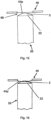
- the second part of the ultrasonic generator can have a concave section opposite the outlet end of the wick, with the passages of the second part of the ultrasonic generator being formed in the concave section. Due to said concave section, the invention ensures that the second part of the ultrasonic generator, both in the rest position and particularly in its oscillating state, is always sufficiently far away from the wick and its outlet end so that the oscillation of the second part of the ultrasonic generator is not impaired by contact with the wick.
- the present invention also provides a method for generating an aerosol using an aerosol generating device with a wick, which aerosol generating device may be the aforementioned device according to the invention.
- the method according to the invention provides that a liquid used to generate the aerosol is a water-based nicotine liquid, the liquid having a surface tension that forms a pool of liquid at the outlet end of the wick for transfer to the ultrasonic generator.
- the liquid can contain antimicrobial substances.
- antimicrobial substances is to be understood to mean that this can be at least one substance that at least inhibits or even prevents the growth of microbes.
- a characteristic feature is that the liquid is a water-based nicotine liquid, with other liquid components, which may prevent contamination of the aerosol generating device, the surface tension the liquid to such an extent that there is no longer an accumulation of liquid at the outlet end of the wick.
- the liquid contains at least one substance selected from the group consisting of hydrogen peroxide, essential oils, silver ion solution, and sodium chloride as a germ-inhibiting substance.
- the liquid can contain a combination of substances selected from the group consisting of hydrogen peroxide, essential oils, silver ion solution, and/or sodium chloride.
- An aerosol generating device comprises a container with a tank formed therein for storing a liquid to be sprayed, wherein the container has: an outlet opening, an ultrasonic generator, by means of which the aerosol can be generated from the liquid, a mouthpiece attached to the container adjacent to its outlet opening, which mouthpiece has an outlet opening for releasing the aerosol generated by the ultrasonic generator, and a wick arranged in the outlet opening of the container for transporting the liquid from the tank to the ultrasonic generator, wherein the wick has an inlet end arranged inside the tank for receiving the liquid stored in the tank and an outlet end arranged adjacent to the ultrasonic generator for providing the liquid to the ultrasonic generator.
- the ultrasonic generator is arranged between the outlet opening of the mouthpiece and the wick.
- Characteristic features of the invention are that the liquid is a water-based nicotine liquid, that the liquid contains antimicrobial substances, and that the liquid has a surface tension with which a collection of liquid forms at the outlet end of the wick for transfer to the ultrasonic generator.
- the liquid contains nicotine in an amount selected from a range of 0.05 mg/ml to 20 mg/ml.
- the liquid can contain sodium chloride in an amount of 0.5 to 3 percent by weight, based on the proportion of water.
- the liquid can expediently contain 0.9 percent by weight of sodium chloride (based on the proportion of water).
- sodium chloride has two effects on the properties of the liquid to be nebulized: On the one hand, it has preservative properties and, as already explained, can help prevent microbial contamination.
- sodium chloride also advantageously increases the surface tension of the liquid. This leads, for example, to a desired accumulation of liquid at the outlet end of the wick, which is then suitably absorbed and aerosolized or nebulized by the ultrasonic generator when it is set into vibration.
- the liquid contains: 85% by volume water, 15% by volume ethanol, 0.5 mg/ml nicotine, 0.9% by weight sodium chloride (based on the proportion of water).
- At least one substance selected from the group consisting of hydrogen peroxide, essential oils, silver ion solution, and sodium chloride is introduced into the wick of the device, preferably that a combination of substances selected from the group consisting of hydrogen peroxide, essential oils, silver ion solution, and/or sodium chloride is introduced into the wick.
- a combination of substances selected from the group consisting of hydrogen peroxide, essential oils, silver ion solution, and/or sodium chloride is introduced into the wick.
- An aerosol generating device according to the invention according to a further embodiment, which has an independent significance, comprises a container with a tank formed therein for storing a liquid to be sprayed, wherein the container has an outlet opening, an ultrasonic generator, by means of which the aerosol can be generated from the liquid, a mouthpiece attached to the container adjacent to its outlet opening, which mouthpiece has an outlet opening for releasing the aerosol generated by the ultrasonic generator, and a wick arranged in the outlet opening of the container for transporting the liquid from the tank to the Ultrasonic generator, wherein the wick has an inlet end arranged inside the tank for receiving the liquid stored in the tank and an outlet end arranged adjacent to the ultrasonic generator for providing the liquid to the ultrasonic generator.
- the ultrasonic generator is arranged between the outlet opening of the mouthpiece and the wick.
- An aerosol chamber is formed in the mouthpiece, which is located between the outlet opening of the mouthpiece and the ultrasonic generator, so that the aerosol generated by the ultrasonic generator is released into the aerosol chamber.
- at least one bypass is formed on or in the mouthpiece, through which a fluid connection is formed between the aerosol chamber and an outer region of the mouthpiece, wherein at least one flavored element with a predetermined flavor is arranged on the mouthpiece fluidically between the outlet opening and the bypass of the mouthpiece.
- a method for generating an aerosol using an aerosol generating device with a mouthpiece is also provided, wherein the aerosol generating device used here can be one of the aforementioned devices according to the invention.
- the method according to the invention provides that, together with the aerosol generating device, at least one, in particular replaceable, flavored element with a predetermined flavor is provided and attached to the mouthpiece in such a way that an air flow inhaled by the user together with the generated aerosol flows past the flavored element and/or through the flavored element before inhalation by the user, and thereby the air flow together with the generated aerosol takes on the predetermined flavor of the flavored element.
- the last-mentioned embodiment of the invention is based on the essential finding that by means of an aromatized element which has a predetermined flavor, it is possible in a simple manner is to impart or add this predetermined flavor to the generated aerosol. This can be achieved in a simple manner according to the invention by attaching the said flavored element with the predetermined flavor to the mouthpiece of the aerosol generating device which is the subject of the present invention or is used to carry out the method according to the invention.
- the bypass which is formed on or in the mouthpiece then ensures that the user, when inhaling the generated aerosol, always also sucks in fresh air from outside the mouthpiece, whereby this fresh air flows past the flavored element and/or flows through the flavored element and thus the air flow, together with the generated aerosol, takes on the predetermined flavor of the flavored element.
- the container of the aerosol generating device has a tank for storing or holding a liquid to be aerosolized.
- the wick transports the liquid from the tank (i.e., the liquid stored in the tank) to the ultrasonic generator.
- the wick has an inlet end for receiving the liquid from the tank into the wick.
- the inlet end is arranged inside the container, i.e., in the tank, to receive the liquid.
- the wick has an outlet end that does not have direct contact with the ultrasonic generator.
- the outlet end of the wick supplies the liquid to the ultrasonic generator through its capillary.
- An arcuate water droplet forms at the end of a capillary when the surface tension of the water exceeds capillarity.
- the capillarity of the wick relative to the surface tension of the water-based solution is selected so that the surface tension the water-based solution dominates, resulting in the formation of an arc-shaped water droplet at the end of the capillary.
- the second part of the ultrasonic generator is positioned so far away from the wick that the oscillating second part of the ultrasonic generator only dips into the water droplet without touching the wick itself. This prevents negative frequency interference with the ultrasonic generator, allowing aerosolization to occur as desired. As a result, unwanted droplet coalescence in the aerosol, which would then impede inhalation to the alveoli in the lungs, does not occur.
- the ultrasonic generator applies ultrasound to the liquid picked up by the outlet end of the wick, nebulizing the liquid and generating an aerosol from the liquid.
- the mouthpiece delivers the generated aerosol to an external part of the device, for example, when a user draws it in.
- the tank, wick, and mouthpiece together define a fluid pathway for transporting the liquid from the tank to the ultrasonic generator and for transporting the aerosol generated by the ultrasonic generator to the mouthpiece.
- the ultrasonic generator is positioned directly between the mouthpiece—an outlet port of the mouthpiece—and the wick.
- the fluid pathway also passes through the ultrasonic generator.
- the container has an outlet opening.
- the wick is arranged in the outlet opening such that the wick at least partially or completely fills the outlet opening.
- aerosol generation may also be referred to as nebulization, aerosolization, atomization, atomization and similar terms.
- the feature "arranged in contact” in the sense of the present invention can have the same meaning as “in direct contact”, “arranged in direct physical contact” or “arranged in surface contact”.
- the term "fillings" within the meaning of the present invention can have the same meaning as “completely filled,” “crammed,” “clamped,” or “occupies an entire cross-sectional area.”
- the cross-sectional plane or area is defined perpendicular to the longitudinal axis of the device and/or the tank and/or the guide.
- the operation of the aerosol generating device can be understood as follows:
- the liquid from the tank is drawn into the wick via the inlet end of the wick.
- the drawn liquid migrates through the wick to its outlet end as a result of the capillary action or wicking of the wick.
- the outlet end of the wick makes the liquid available to the ultrasonic generator, whereby according to an advantageous embodiment of the invention, there is no direct contact between the outlet end of the wick and the second part of the ultrasonic generator.
- the outlet end of the wick supplies the ultrasonic generator with the liquid to be nebulized through the capillary.
- an arc-shaped water droplet forms at the end of a capillary due to the surface tension of the water-based liquid.
- the surface tension arises due to the attractive forces between the water molecules at the interface between the water and the air.
- the water rises due to capillarity caused by adhesion and cohesion.
- the capillarity of the wick is selected in relation to the surface tension of the water-based solution in such a way that the surface tension of the water-based solution dominates, resulting in the formation of an arc-shaped water droplet at the end of the capillary, i.e. at the outlet end of the wick.
- the ultrasonic generator generates ultrasound, e.g., when operated or controlled by a user of the device, or activated, e.g., when supplied with electrical energy from a battery or power source.
- the generated ultrasound sprays the liquid provided by the outlet end of the wick, creating the aerosol, which is then mouthpiece to an exterior of the device.
- the atomization and subsequent removal of the liquid from the outlet end of the wick by the action of the ultrasonic generator provides suction or maintains a capillary or wicking action, drawing or transporting the liquid from a container into the inlet end of the wick and from there to the outlet end of the wick.
- the wick can be arranged at a distance from the surface of the ultrasonic generator and can be spatially sealed in such a way that, apart from the liquid transported by the wick, no other liquid can enter the ultrasonic generator.
- the liquid can reach the ultrasonic generator exclusively via the capillary element or the wick.
- the container is designed to be liquid-tight or fluid-tight except for its outlet opening, so that the liquid from the tank is transported to the ultrasonic generator only via the wick.
- This has the advantage of preventing unwanted leaks of liquid from the container and ensuring that the liquid stored in the tank of the container reaches the ultrasonic generator exclusively through the wick.
- the accumulation of liquid, which forms at the outlet end of the wick due to its surface tension, then ensures that liquid is absorbed by the second part of the ultrasonic generator when this second part is set into vibration and deforms towards the outlet end of the wick.
- the wick with its outlet end is in contact with the first part of the ultrasonic generator.
- the wick can be expedient for the wick to be prestressed by a compression spring along its longitudinal extent in the direction of the ultrasonic generator, such that the wick with its outlet end is pressed against the first part of the ultrasonic generator.
- the contact of the wick with the first part of the ultrasonic generator creates a sealing effect to the side, so that the accumulation of liquid at the outlet end of the wick is actually only located centrally opposite the second part of the ultrasonic generator. This ensures effective absorption of liquid in the passages of the second part of the ultrasonic generator when this second part deforms in the direction of the wick during vibration and immerses itself in the liquid as explained.
- the aforementioned spring preload for the wick can be achieved by arranging the compression spring in axial alignment with the wick and bearing against an end face of the wick where its inlet end is formed.
- the compression spring is arranged on the wick at its lower end face, which is opposite the ultrasonic generator.
- the compression spring can be supported on a base region of the container or on an associated lid, so that the spring force is exerted on the wick in the direction of the ultrasonic generator.
- the aforementioned spring preload for the wick has the advantage that the wick always forms a tight seal against the first part of the ultrasonic generator. On the one hand, this creates a sealing effect with respect to the outlet end of the wick, preventing any uncontrolled flow or escaping of the liquid that accumulates at the outlet end of the wick due to its surface tension. Furthermore, the spring preload ensures that the vibrations of the ultrasonic generator induced by its first part can be "accompanied" by the wick. This means that these vibrations of the first part can be transmitted to the wick without the contact between the wick and the first part of the ultrasonic generator being lost.
- the wick's outlet end is continuously pressed against the first part of the ultrasonic generator due to the spring preload of the compression spring.
- the vibrations are transmitted from the first part of the ultrasonic generator to the wick, its contact with the first part of the ultrasonic generator is maintained or not lost.
- the sealing effect described above which is achieved by the contact of the wick with the first part of the ultrasonic generator, remains unchanged even during vibration.
- the wick can be made of woven or non-woven fabric, such as cotton.
- any conduction or movement or transport of the liquid through the wick and/or in the wick and/or within the wick may be due to wicking or capillary action, e.g., if it is forced or effected or brought about by aerosolization of the liquid at the outlet end of the wick by the ultrasound generated by the ultrasonic generator.
- a material of the wick may be such that capillaries of the wick hold the liquid so that the liquid does not escape by itself, ie in the absence of the wick force generated by the operation (ie the ultrasound generation) of the ultrasonic generator. Only by the vibrations of the Ultrasonic generator, the liquid in the wick can escape from the capillaries of the wick.
- a position and/or orientation of the wick may be located or fixed with respect to the container, in particular with respect to the outlet opening of the container, for example, but not exclusively, by means of a press fit or interference fit.
- the above-mentioned fluid conduction path can be understood in the sense of the present invention as comprising at least two sections or parts or segments - a first section or segment, which can be referred to as a liquid transport section or segment, and a second section or segment, which can be referred to as an aerosol transport section or segment.
- the liquid transport section may be defined at least by the wick, for example, by the inlet end of the wick, the outlet end of the wick, and the intermediate or middle part of the wick (i.e., the part of the wick extending between the inlet end and the outlet end of the wick).
- the liquid is transported from the tank to the ultrasonic generator via the liquid transport section.
- the liquid transport section extends from the tank to the ultrasonic generator.
- the aerosol transport section can be defined by at least one space, chamber, or channel between the ultrasonic generator and an outlet opening (i.e., a discharge opening) of the mouthpiece.
- the aerosol generated at and by the ultrasonic generator is transported to the outlet opening of the mouthpiece via the aerosol transport section.
- the outlet opening may be an opening of the mouthpiece through which or via which the aerosol is ultimately discharged or dispensed from the mouthpiece and/or the aerosol generating device, for example to a user.
- the liquid transport section and the aerosol transport section are connected to each other or overlap continuously or partially, with these two sections together forming the fluid conduction path.
- the fluid conduction path extends through the ultrasonic generator.
- the ultrasonic generator may have a receiving surface (also referred to as the first surface or bottom surface or wick-side surface or bottom surface) and an exit surface (also referred to as the second surface or top surface or discharge opening-facing surface or top surface).
- the receiving surface and the exit surface of the ultrasonic generator can be inverted sides or surfaces, i.e. opposite sides or surfaces of the ultrasonic generator.
- the receiving surface of the ultrasonic generator faces the wick. According to an advantageous embodiment of the invention, this receiving surface is not in direct physical contact (surface contact) with the wick, i.e., with the outlet end of the wick.
- the receiving surface of the ultrasonic generator collects the liquid from an arc-shaped drop that forms on or at the outlet end of the wick.
- the exit surface of the ultrasonic generator faces the exit opening of the mouthpiece.
- the aerosol generated on and by the ultrasonic generator leaves the ultrasonic generator from the exit surface towards the exit opening of the mouthpiece.
- the ultrasonic generator can be configured to operate at a frequency in the range of 1.4 kHz to 3 MHz.
- the aerosol generating device in particular the ultrasonic generator, can be configured to generate aerosol from a water-based liquid (i.e., a liquid containing 80 wt% or more of water), wherein the aerosol has droplets with a size or an average size of 10 ⁇ m or less, in particular less than or equal to 5 ⁇ m, and/or equal to or greater than 1 ⁇ m, in particular greater than or equal to 2 ⁇ m, and/or without heating at least one of the fluids, the liquid and the aerosol (i.e., by maintaining a temperature of the liquid, a temperature of the aerosol can correspond to the temperature of the liquid).
- the aerosol can comprise a plurality of droplets with a size distribution with an average or mean value less than or equal to 10 ⁇ m, in particular less than or equal to 5 ⁇ m.
- the ultrasonic generator may comprise a first part, for example, a piezoelectric or piezoceramic part or element, and a second part, for example, a mesh or metal grid part, or a part with a plurality of passages formed therein, or a perforated part.
- the ultrasonic generator may comprise a first part comprising a piezoelectric element and a second part having a plurality of passages (for example, a mesh or a perforated plate) for allowing the fluid to pass through.
- the outlet end of the wick is not in contact with the second part of the ultrasonic generator. Consequently, the outlet end of the wick is also not in contact with the passages formed in the second part of the ultrasonic generator. This provides the advantage of the invention that the vibrations of this second part of the ultrasonic generator are not influenced or impaired by the wick during operation of the aerosol generating device.
- the second part of the ultrasonic generator can be set into vibration by its first part.
- the second part of the ultrasonic generator may be disc-shaped or circular.
- a diameter of the second part of the ultrasonic generator may be equal to or greater than a diameter of the outlet opening of the container and/or a diameter of the outlet end of the wick (which, as explained above, is not in contact with the second part).
- the second part of the ultrasonic generator can have a flat shape.
- the second part of the ultrasonic generator it is possible for the second part of the ultrasonic generator, as already mentioned above, to have a concave section.
- this concave section of the second part of the ultrasonic generator has a curved shape that extends away from the wick.
- the shape of the outlet end of the wick can also have a curved shape.
- a shape of the wick at the outlet end may correspond to the shape of the second part of the ultrasonic generator.
- the shape of the outlet end of the wick may also be planar.
- the second part of the ultrasonic generator may have a curved shape that protrudes toward or relative to the wick—for example, a concave or convex shape, such as a concave or convex dome shape.
- the shape of the outlet end of the wick and the shape of the second part of the ultrasonic generator can be be adapted, matched, corresponding, similar, or complementary. However, direct contact between the outlet end of the wick and at least the second part of the ultrasonic generator should be prevented.
- the second part of the ultrasonic generator can be surrounded by the first part.
- the first part of the ultrasonic generator may have an annular shape, for example an annular circular or disc shape, and the second part may be arranged at or in the center of the annular shape.
- the receiving surface and the exit surface of the ultrasonic generator can be surfaces of its second part.
- the receiving surface and the exit surface of the ultrasound generator may be in fluid communication with each other via the tissue or the passages or perforations of the second part.
- the fluid conduction path may extend through the second part of the ultrasound generator, i.e., through the fabric or the passages or perforations of the second part from the receiving surface to the exit surface of the ultrasound generator.
- the passages or mesh or perforations may form a part, segment, or portion of the fluid conduction path.
- a portion or segment of the fluid conduction path i.e. the portion disposed in or within or through the ultrasonic generator, may be surrounded by the first part of the ultrasonic generator.
- the first part of the ultrasonic generator may have an annular shape, for example an annular circular or disc shape, and the fluid conduction path may extend or pass through the center of the annular shape.
- the wick is arranged in the outlet opening of the container in such a way that the wick at least partially fills or completely fills the outlet opening.
- the wick can fill the outlet opening in such a way that the container is leak-proof or tight with regard to the liquid stored therein.
- the container can be leak-proof if the wick is positioned in and fills the outlet opening.
- the wick can fill the outlet opening of the container in such a way that a contact area between the wick and the opening is so leak-proof that the container is leak-proof and thus tight.
- the wick may comprise at least two sections or parts or segments, an inner or first section of the wick arranged to project out of the outlet opening and into the tank, and an opening or second section of the wick arranged in or within the outlet opening (i.e., not projecting from either side of the outlet opening or simply being confined or flush with the outer and inner surfaces of the container).
- the two sections or parts or segments of the wick may be formed as one piece.
- the wick may optionally comprise a third portion or part or segment - an outer portion of the wick disposed projecting from the outlet opening to an outer side of the container, i.e., disposed outside the tank and outside the outlet opening.
- the wick When inserting the wick into the outlet opening, the wick may be pressed into the outlet opening, i.e. by walls or surfaces (of the container) defining the outlet opening, whereby the wick thus assumes the cross-sectional shape and/or size (e.g. diameter) of the outlet opening.
- a standard cross-sectional shape of the wick e.g., the opening portion of the wick, and a cross-sectional shape of the outlet opening may be the same, e.g., Both can have a circular shape.
- a standard cross-sectional shape of the wick e.g., the opening portion of the wick, and a cross-sectional shape of the outlet opening may be different, and the wick is pressed into the outlet opening when inserted into the outlet opening, thus assuming the cross-sectional shape of the outlet opening.
- a standard cross-sectional shape of the wick can be understood as a cross-sectional shape of the wick before it is inserted into the outlet opening.
- a standard cross-sectional area of the wick e.g., the opening portion of the wick, may be larger than the cross-sectional area of the outlet opening.
- a preset cross-sectional area of the wick can be understood as a cross-sectional area of the wick before it is inserted into the outlet opening.
- the outlet opening may be completely filled with the wick or packed by the wick. In other words, the entire cross-sectional area of the outlet opening is occupied by the wick, so that the liquid in the tank flows through the outlet opening only over or through the wick.
- the wick is arranged through or in the outlet opening such that no gap, air gap, or spatial gap remains in the outlet opening, i.e., between an outer surface (e.g., an outer peripheral surface) of the wick and a surface of the container defining the outlet opening. Since there is no space, channel, or gap between the outer surface of the wick and the surface of the container that defines the outlet opening, any unintentional flow of liquid or vapor out of the container is reduced or eliminated.
- the wick may be inserted or pressed into the outlet opening, for example in such a way that the entire circumferential surface of the outlet opening is in direct contact (or in surface-to-surface contact) with an outer peripheral surface of the wick.
- the container for example the tank defined by the container, may be liquid-tight or hermetically sealed or fluid-tight, in particular for the flow of liquid from an interior of the container (i.e. the tank) to an exterior of the container (i.e. (i.e., outside an outer surface of the container).
- the container can be liquid-tight or hermetically sealed, except for its outlet opening, so that the liquid from the tank is transported to the ultrasonic generator only via the wick arranged in the outlet opening.
- the outlet opening of the container may be the only exit or drainage opening from the tank to an exterior of the container.
- the wick may comprise a solid body configured to exhibit capillary action or wicking.
- This reservoir may have a volume of 3 ml or less, particularly 2 ml or less.
- the container may have a guide that is tubular and extends from the outlet opening of the container into the tank.
- the guide and the container may be formed integrally.
- an inner diameter of the guide may be equal to a diameter of the outlet opening of the container.
- the guide may have a receiving space.
- the wick is accommodated in the receiving space.
- the guide may only occupy a portion of the tank.
- the guide may occupy between 10 and 90 percent of the total tank volume, or between 20 and 80 percent of the total tank volume, or between 30 and 70 percent of the total tank volume, or between 10 and 30 percent of the total tank volume.
- the receiving space may be continuously connected to the outlet opening and/or be in fluid communication with the outlet opening.
- the receiving space may be formed sequentially with the outlet opening.
- the outlet opening can preferably be in fluid communication with the tank exclusively via the receiving space.
- the receiving space can be concentric and/or coaxial with the outlet opening.
- a cross-sectional area of the receiving space can be filled by the wick.
- the cross-sectional area of the receiving space can be equal to or smaller than a cross-sectional area of the outlet opening. Additionally or alternatively, the cross-sectional area of the receiving space can be constant along a longitudinal axis thereof.
- An entire or complete internal volume of the guide may be filled by the wick or completely filled or packed.
- the receiving space can be completely or completely packed (in cross-section and longitudinal direction) or completely packed by the wick.
- the standard cross-sectional shape of the wick e.g., the inner portion of the wick, and a cross-sectional shape of the receiving space may be identical, e.g., both may be circular.
- the standard cross-sectional shape of the wick e.g., the inner portion of the wick, and a cross-sectional shape of the receiving space may be different, and the wick, when inserted into the receiving space, may be forced through a peripheral wall (defining the receiving space) of the guide, thus assuming the cross-sectional shape of the receiving space.
- the standard cross-sectional area of the wick e.g. the inner section of the wick, may be larger than the cross-sectional area of the receiving space.
- the container for example the one formed by the Container defined tank, liquid-tight or hermetically sealed or fluid-tight.
- the container for example the tank defined by the container, may be liquid-tight or hermetically sealed or fluid-tight, in particular for the flow of liquid from the interior of the container (i.e. from the tank) to the exterior of the container (i.e. outside an exterior surface of the container).
- the outlet opening and the associated receiving space may define or form the only exit from the tank to the outside of the container.
- the outlet opening and/or the receiving space can be completely filled with the wick, or can be stuffed or packed by the wick. In other words, the entire cross-sectional area of the outlet opening and/or the receiving space is occupied by the wick, so that the liquid in the tank flows through the outlet opening and/or the receiving space only via the wick, or through an interior of the wick, or through a body of the wick, or through capillary channels or interstices of the wick.
- the wick can be arranged through or in the outlet opening and/or the receiving space such that no gap, air gap, or air channel remains in the outlet opening and/or the receiving space between an outer surface, e.g., an outer peripheral surface, of the wick and the surface of the container defining the outlet opening and/or the peripheral wall of the guide defining the receiving space. Since there is no space or channel or gap between the outer surface of the wick and the surface of the container defining the outlet opening and/or the peripheral wall of the guide defining the receiving space, any unintended flow of liquid or vapor from the container is reduced or eliminated.
- the container can be liquid-tight except for the outlet opening and the associated receiving space, so that the liquid from the tank is transported to the ultrasonic generator only or exclusively via the wick arranged through the receiving space and the outlet opening.
- the guide may have an inlet end with an inlet or inlet hole.
- the inlet end of the wick may be in fluid communication with the tank via the inlet of the guide.
- the guide may have a circumferential wall extending between the inlet end of the guide and an outlet end of the guide.
- the outlet end of the guide may have an outlet or outlet hole communicating with the outlet opening.
- the outlet of the guide may have the same diameter and/or cross-sectional area as the outlet opening of the container.
- the outlet end of the guide can be connected or coupled to the inner surface of the container.
- the coupling can be fluid-tight or liquid-tight.
- the surrounding wall of the guide can be so liquid-tight that the liquid in the receiving space only enters the wick via the inlet of the guide.
- a gap may be defined between the guide, i.e., the inlet end of the guide, and the inner surface of the container.
- the liquid stored in the tank is absorbed into the wick through the gap.
- the wick may be arranged such that it projects from the guide, i.e. from the inlet end of the guide, into the tank.
- the wick may be arranged such that it projects from the guide, i.e. from the inlet end of the guide, into the gap.
- the guide can hermetically separate the receiving space of the container from the ultrasonic generator, except through the receiving space.
- the wick may protrude from or from the outlet opening to the ultrasonic generator. This means that the outlet opening may be spaced apart from the ultrasonic generator.
- the wick may protrude from the outlet opening and extend beyond an outer surface of the container. In other words, the protruding portion or outer portion or part of the capillary element or wick may be located entirely outside the container.
- a length of the guide extending from the outlet opening of the container into the tank may be equal to or greater than 50 percent of a length of the tank, or equal to or greater than 70 percent of a length of the tank, may be equal to or greater than 80 percent of a length of the tank, or may be equal to or greater than 90 percent of a length of the tank.
- a length of the wick extending from the outlet opening of the container into the tank may be equal to or greater than 50 percent of a length of the tank, or may be equal to or greater than 70 percent of a length of the tank, may be equal to or greater than 80 percent of a length of the tank, or may be equal to or greater than 90 percent of a length of the tank.
- a (total) length of the wick may be greater than a length of the guide and/or may be greater than a combined length of the guide and the outlet opening.
- the length of the guide may be measured from an edge of the outlet opening facing the receiving space.
- the length of the tank may be measured from an edge of the outlet opening facing the tank to a bottom surface of the tank, i.e., an area of the bottom wall of the tank that defines the tank.
- the guide may have a cylindrical shape, e.g. the shape of a right circular cylinder, and may have different cross-sectional shapes, such as circular, triangular, polygonal.
- the wick may have a cylindrical shape, e.g., the shape of a right circular cylinder, and may have various cross-sectional shapes, such as circular, triangular, polygonal.
- the container may have a cylindrical shape, e.g. the shape of a right circular cylinder or a cuboid, and may have different cross-sectional shapes, such as circular, triangular, polygonal.
- the container may also have different parts or sections with different shapes - such as a first part or segment with a cylindrical shape and a second part or segment with a frustoconical or cuboidal or frustoconical or frustoconical shape.
- the guide and/or wick may extend along a longitudinal axis of the container and/or the aerosol generating device.
- the guide and/or wick may be coaxial and/or concentric with the container and/or with the aerosol generating device.
- the guide and/or the wick may be arranged along the longitudinal axis of the container and/or the aerosol generating device.
- the longitudinal axis may be a central longitudinal axis of the container and/or the aerosol generating device.
- the container may comprise a body.
- the body may be formed as a single piece, e.g., molded or 3D printed in one piece. Alternatively, the body may be formed in multiple parts.
- the parts may be connectable to one another with a fluid-tight joint to form the body of the container.
- the parts may be molded or 3D printed.
- the container may have an inlet opening for filling or refilling the liquid into the tank.
- the container may have a closure for closing the inlet opening.
- the closure may be a seal or cap formed of an elastomeric material, such as rubber, that can be detached from the opening to refill the tank.
- a refilling device e.g., a syringe needle
- the closure can be a valve, e.g. a one-way valve or a filling valve (filling valve or refilling valve).
- the container may have a seal or sealing element at the outlet opening and in contact with an outer surface of the wick.
- the sealing element may be disposed inside the outlet opening or outside the outlet opening.
- the sealing element may protrude into the outlet opening.
- An example of the sealing element may be a gasket, e.g., a gasket formed from an elastic material such as a rubber gasket.
- the device may further comprise a holding element arranged between the mouthpiece and the container and/or arranged on or on the container to support or mount or fix the ultrasonic generator.
- the ultrasonic generator can be mounted on the holding element or accommodated in it.
- the holding element may, for example, be formed from an elastic or elastomeric material, such as silicone or rubber, and may be a cushion to hold and support the ultrasonic generator.
- the retaining element may be configured to dampen the vibrations and/or noise generated by the ultrasonic generator transmitted to the container and/or the mouthpiece and/or an external surface of the device.
- the container may include a container connector, and the holding element may include a holding element connector.
- the container connector and the holding element connector may correspond to each other and may engage with each other to fix or couple the container and the holding element to the ultrasonic generator mounted thereon.
- the coupling may be releasable or reversible.
- the mouthpiece, the ultrasonic generator and the wick can be aligned axially or linearly, i.e. in a straight line.
- the ultrasonic generator can be stacked in a straight line on the outlet opening of the container and the wick; and the mouthpiece can be stacked in a straight line on the ultrasonic generator.
- the longitudinal axis of the ultrasonic generator may mean a longitudinal axis of the first part and the second part of the ultrasonic generator.
- the first part and the second part may have the same longitudinal axis.
- the longitudinal axis of the guide may mean the longitudinal axis of the receiving space of the guide.
- the longitudinal axis of the container may mean the longitudinal axis of the receiving space of the container.
- the wick can be placed in the tank without completely filling the tank.
- a section or portion of the sub-volume or segment of the tank may be free of wick or absorbent material and may be a free space or volume to receive and hold the liquid in a free form or state (i.e., without being adsorbed or held by the wick or any absorbent material). This allows at least a portion of the tank to be used exclusively to hold the liquid to be nebulized, which can then be transported via the wick to the ultrasonic generator.
- the wick may be arranged within the tank and fill a cross-section of the tank or the entire tank.
- the guide may optionally be omitted.
- the wick can be arranged in the tank such that it fills a cross-section of the tank, i.e., is in contact with the inner surface of the tank.
- the outlet opening can have a diameter and/or a shape and/or a cross-sectional area corresponding to that of the receiving space.
- the wick can be arranged such that it fills a cross-sectional area of a first portion of the tank.
- a second portion of the tank can be between the wick and a bottom region of the tank. The second portion is free of wick material and/or capillary material.
- the wick can fill the entire tank.
- the container may comprise a guide segment that defines the receiving space or may be formed entirely by this guide segment.
- the wick can be arranged in the outlet opening, wherein the guide segment is arranged such that the wick fills or completely fills the outlet opening and/or the receiving space of the guide segment.
- the guide segment can absorb the liquid adsorbed in the arranged wick.
- the guide segment can form the entire tank.
- the container may have a reservoir segment in addition to the guide segment.
- the reservoir segment does not contain the wick or is free of the wick, i.e., it is not filled by the wick and can therefore absorb the liquid therein.
- the reservoir segment of the tank may be free of the wick or any absorbent material and may be a free space or volume to receive and hold the liquid in a free form or state (i.e., without being adsorbed or held by the wick or any absorbent material). Consequently, the reservoir segment may be used exclusively to receive the liquid to be aerosolized. which can then be transported to the ultrasound generator via the wick arranged in the guide segment, as explained.
- the tank, the wick and the mouthpiece define a fluid conduction path for transporting the liquid from the tank to the ultrasonic generator and for transporting the aerosol generated by the ultrasonic generator to the mouthpiece, preferably that the fluid conduction path runs through the ultrasonic generator and the container, further preferably that the wick is arranged in the outlet opening of the container and fills the outlet opening.
- the liquid used in conjunction with the aerosol generating device and method according to the invention may be a water-based nicotine liquid.
- this liquid it is important for this liquid to have a surface tension sufficient to form a sufficient pool of liquid at the outlet end of the wick for transfer to the ultrasonic generator.
- the liquid may contain at least one additional ingredient, e.g. tobacco extract, nicotine extract, flavoring such as mint extract, clove extract, etc.
- additional ingredient e.g. tobacco extract, nicotine extract, flavoring such as mint extract, clove extract, etc.
- An amount of ethanol and/or at least one additional component in the liquid may be equal to or greater than 10% by weight and equal to or less than 20% by weight.
- the liquid must not contain one or more or all of the following substances: glycerin, propylene glycol, and oil.
- the liquid must not contain at least one or all of glycerin, propylene glycol, and oil, preferably with the exception of essential oils and/or flavor additives.
- the temperature of the liquid and the temperature of the aerosol can be the same.
- no heating effect is performed by the ultrasonic generator.
- no heating effect is required to convert the liquid into the aerosol.
- No heating action shall be carried out at the time and/or place of aerosolization, i.e. the generation of aerosol from the liquid.
- the ultrasonic generator can oscillate at a frequency of less than or equal to 3.5 MHz (megahertz) or less than or equal to 3 MHz, in particular at a frequency in the range from 1.4 kHz to 3 MHz.
- a diameter of the droplets of the aerosol generated by the ultrasonic generator can be less than or equal to 10 ⁇ m, in particular less than or equal to 5 ⁇ m and/or equal to or greater than 1 ⁇ m, in particular greater than or equal to 2 ⁇ m.
- Droplet size can be measured by light diffraction, e.g., laser light diffraction, or by light scattering, e.g., laser light scattering.
- suitable droplet size measurement systems include the Spraytec TM from Malvern Panalytical Ltd or the LS 13 320 XR particle analyzer from Beckmann Coulter GmbH.
- liquid-tight in the context of the present invention means impermeable to any fluid, including a gas, vapor, or liquid, e.g., impermeable to the liquid stored in the tank or to the vapor generated from the liquid stored in the tank.
- liquid-tight in the context of the present invention means impermeable to any liquid, e.g. impermeable to the liquid stored in the tank.
- 'upstream', 'downstream', 'top', 'upper', 'bottom', 'bottom' and similar expressions may be understood in relation to a direction or path of the liquid (to be aerosolized) from the tank to the ultrasonic generator and of the aerosol from the ultrasonic generator to the mouthpiece.
- the unintentional accumulation of droplets on the surface of the ultrasonic generator facing the outlet opening of the container i.e., the inner surface or the underside of the ultrasonic generator, is reduced or prevented. Consequently, any migration of the liquid through the ultrasonic generator, e.g., through the opening or passages or meshes of the ultrasonic generator to the top of the ultrasonic generator, is reduced or stopped, thus reducing or stopping droplet formation on the top of the ultrasonic generator.
- the above-mentioned effect not only increases the speed and efficiency of restarting and nebulization, but also allows the use of liquid with high water content.
- FIG. 1 and 2 show perspective views of an exemplary embodiment of an aerosol generating device 1 (hereinafter also referred to as device) in an assembled or mounted state.
- Fig. 3 shows the aerosol generating device 1 of Fig. 1 in a disassembled or dismantled state.
- the aerosol generating device according to the invention Fig. 1 or Fig. 3 may be a personal vaporizer, an inhaler, an electronic cigarette, or e-cigarette. It should be noted that, although in the present description, the device is illustrated as having a structure that can be assembled and disassembled, the device according to the invention is not limited thereto. This means that the device 1 according to the invention may have a unitary structure, ie, it cannot be assembled and disassembled, or it may have a structure that can be assembled and disassembled, but differs from the structure according to the Fig. 1 - 3 differs.
- the aerosol generating device 1 can extend along a longitudinal axis 1x (cf. Fig. 2 , Fig. 11 ).
- the aerosol generating device 1 may have a linear shape extending along the longitudinal axis 1x, such as a rod shape or bar shape.
- the aerosol generating device 1 may comprise a main part (or handpiece) 8 and a cartridge part 9 (hereinafter always referred to as "cartridge").
- the cartridge 9 is Fig. 3 shown when it has been dismantled from the main part 8, ie removed therefrom.
- the aerosol generating device e.g. its main part 8, can accommodate a power supply (not shown), such as a battery unit for powering an ultrasonic generator (not included in the Fig. 1-3 shown and explained later) and/or other electronic components.
- a power supply such as a battery unit for powering an ultrasonic generator (not included in the Fig. 1-3 shown and explained later) and/or other electronic components.
- the aerosol generating device 1 may also include a control device (not shown) for controlling operation of the power supply and the ultrasonic generator and/or other components of the device 1.
- the aerosol generating device 1 may further include a charging port 82 for charging the power supply of the device 1 by providing an external power supply or one or more indicators such as LED indicators 84, 88. These indicators serve to indicate the operating state of the device 1 and/or a charging state of the device 1, e.g., a fully charged state, a low battery state, a state in which the ultrasonic generator is powered to generate ultrasound, or a standby state.
- a charging port 82 for charging the power supply of the device 1 by providing an external power supply or one or more indicators such as LED indicators 84, 88. These indicators serve to indicate the operating state of the device 1 and/or a charging state of the device 1, e.g., a fully charged state, a low battery state, a state in which the ultrasonic generator is powered to generate ultrasound, or a standby state.
- the aerosol generating device 1 can have a user interface 88 (cf. Fig. 1 ), e.g., a button, such as an ON/OFF button, that a user can actuate, e.g., press, to control the function or operation of the device 1, such as inputting a user command to implement the power supply of the ultrasonic generator to generate or produce ultrasound for aerosol.
- a user interface 88 e.g., a button, such as an ON/OFF button, that a user can actuate, e.g., press, to control the function or operation of the device 1, such as inputting a user command to implement the power supply of the ultrasonic generator to generate or produce ultrasound for aerosol.
- the device 1 may have a surface feature 89, such as a logo or branding or a non-slip surface modification.
- the aerosol generating device 1, e.g., the cartridge 9, may comprise a reservoir or a container (not included in the Fig. 1 - 3 shown, but explained later) for receiving or containing a liquid to be nebulized to produce aerosol, and a mouthpiece 50 for delivering the aerosol thus produced to an outside of the device 1.
- the main part 8 and the cartridge 9 may be formed as one body or have a structure which can be connected to one another by means of engaging parts 8x, 9x which are provided on the main part 8 and the cartridge 9 (cf. Fig. 3 ), can be assembled and disassembled.
- the main part 8 may contain a main engagement part 8x and the cartridge 9 may contain a cartridge engagement part 9x (cf. Fig. 3 ).
- the main engagement part 8x can be reversibly engaged with and released from the cartridge engagement part 9x in order to connect or separate the main part 8 and the cartridge 9. In this way, the device 1 with its components, main part 8 and cartridge 9, can be assembled or disassembled again if necessary.
- Electrical contacts or connections 9y to electrically or signal-technically connect the power supply (contained in the main part 8) and the ultrasonic generator 40 (contained in the cartridge 9) to each other.
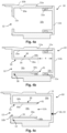
- the device 1, ie the cartridge 9, comprises a container 10 as shown in the Fig. 4a, 4b and 4c shown, with an outlet opening 12, a wick 20 fitted into the outlet opening 12, as shown in the Fig. 5a and 5b shown, and an ultrasonic generator 40 (also referred to as ultrasonic transducer or probe or head or actuator) arranged opposite the wick 20, as shown in the Fig. 9a and Fig. 9b is shown.
- an ultrasonic generator 40 also referred to as ultrasonic transducer or probe or head or actuator
- Fig. 7 shows an exemplary embodiment of the ultrasonic generator 40, which is part of the aerosol generating device 1 according to the invention and is mounted in the cartridge 9.
- the ultrasonic generator 40 can have a first part 42 comprising a piezoelectric element; and a second part 44 having a plurality of passages 44p or a mesh 44p, e.g., a metallic mesh.
- the passages 44p or the mesh 44p make the second part 44 of the ultrasonic generator 40 permeable to liquid and in particular to the aerosol generated by the ultrasonic generator 40. Further details on the ultrasonic generator 40 and its interaction with the wick 20 are explained separately below.
- the first part 42 of the ultrasonic generator 40 may have an annular shape, wherein the second part 44 of the ultrasonic generator 40 may be arranged in a center of the annularly shaped first part 42.
- the second part 44 of the ultrasonic generator 40 has two opposite or inverted sides or surfaces - a receiving surface and an exit surface - which are in fluid communication with each other via the mesh 44p or the passages 44p.
- the receiving surface of the second part 44 of the ultrasonic generator 40 can be understood as the surface of the second part 44 facing the outlet opening 12 and the outlet end 22 of the wick 20.
- the exit surface of the second part 44 can be understood as the surface of the second part 44 facing the mouthpiece 50 or facing an exit opening 50h of the mouthpiece 50.
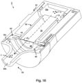
- Fig. 10 , 11 and 12 show an exemplary embodiment of the device 1, in which the container 10, the wick 20, the ultrasonic generator 40 and the mouthpiece 50 are shown in their arrangement relative to one another.
- the container 10 may include a guide 30 as shown in Fig. 4b and 4c shown, or the guide 30 can be moved as shown in Fig. 4a shown, not included.
- the Fig. 10 and 11 show an exemplary embodiment of the device 1 with the guide 30. However, the Fig. 10 and 11 The arrangement shown can be applied mutatis mutandis to the device 1 without the guide 30.
- Figure 12 shows an exemplary embodiment of the device 1 without the guide 30.
- the container 10 comprises a liquid reservoir in the form of an accommodation space 10s (hereinafter always referred to as "tank").
- This tank 10s serves to store or hold a liquid 3 (in Fig. 10 symbolized by three dots) that is to be sprayed.
- the container 10 may be formed from a polymeric material, such as plastic.
- the container 10 may have at least a part or segment that is transparent and allows a view of an interior of the container 10, i.e., the tank 10s, whereby a user can see the level of the liquid present in the tank 10s.
- the container 10 may include a body 11.
- the body 11 may include the outlet opening 12.
- the body 11 may be formed in one part, ie it may be formed in one piece, as in Fig. 4c shown; or may be formed by a plurality of parts 11a, 11b, as shown in the Fig. 4a and 4b shown, such as a first body segment or part 11a, e.g., a main container body 11a, and a second body segment or part 11b, e.g., a container lid 11b.
- the parts 11a, 11b can be connected with a liquid-tight connection 11x therebetween to form or completely assemble the body 11 of the container 10.
- the parts 11a, 11b can be reversibly connectable with the liquid-tight connection 11x, i.e., they can be coupled and decoupled from each other.
- the liquid-tight connection 11x can be a screw and thread connection or a press-fit connection, etc.
- the container 10 - regardless of whether it is formed in one part, as in Fig. 4c shown, or assembled by several interconnectable parts is, as in Fig. 4a and 4b shown - may define the tank 10s fluid-tight or liquid-tight or hermetically sealed with respect to an exterior of the container 10, except for the outlet opening 12 or adjacent areas thereof.
- the tank 10s of the container 10 is in fluid communication with an outside of the container 10 to allow the liquid to flow from the tank 10s to the outside of the container 10 only via the outlet opening 12.
- the container 10 or the body 11 of the container 10 may have the guide 30 extending from the outlet opening 12 into the tank 10s.
- the guide 30 may have a hollow tubular shape and define a receiving space 30s.
- the guide 30 may be attached to or contact a portion of the inner surface of the container 10 that surrounds or circumscribes the outlet opening 12.
- the outlet opening 12 may be located on an inner surface of the container 10 within the guide 30 or within a peripheral wall 35 of the guide 30.
- a contact interface or portion 38 between the guide 30 and the inner surface 10a of the container 10 may be liquid-tight or hermetically sealed.
- the guide 30 may be integrally formed with the portion of the inner surface of the container 10 that surrounds or circumscribes the outlet opening 12.
- the guide 30 may comprise a hollow, tubular body having an outlet end 32 connected to the inner surface 10a of the container 10, surrounding or surrounding the outlet.
- the outlet end 32 of the guide 30 may have an outlet 32h in fluid communication with the outlet opening 12.
- the hollow, tubular body of the guide 30 may have an inlet end 31 (cf. Fig. 4b, Fig. 4c ) which is arranged inside the tank 10s and from the Inner surface 10a of the container 10 (or in the embodiment of Fig. 4a and Fig. 4b : is spaced from the container lid 11b) by a gap 4.
- an inlet end 31 cf. Fig. 4b, Fig. 4c
- the hollow, tubular body of the guide 30 may have an inlet end 31 (cf. Fig. 4b, Fig. 4c ) which is arranged inside the tank 10s and from the Inner surface 10a of the container 10 (or in the embodiment of Fig. 4a and Fig. 4b : is spaced from the container lid 11b) by a gap 4.
- the inlet end 31 of the guide 30 can have an inlet 31h (cf. Fig. 4c ) which is in fluid communication with the tank 10s.
- the peripheral wall 35 of the guide 30 may extend longitudinally between the inlet end 31 and the outlet end 32 of the guide 30.
- the tank 10s of the container 10 is in fluid communication with an outside of the container 10 to allow the liquid to flow from the tank 10s to the outside of the container 10 only via the guide 30 and the outlet opening 12, for example only via the inlet 31h, the tank 30s, the outlet 32h and the outlet opening 12 arranged one behind the other.
- the guide 30 may be arranged within the tank 10s in a cantilevered arrangement and may be connected to the inner surface 10a of the container 10 only at one end of the guide 30, i.e., the outlet end 32 of the guide 30.
- the peripheral wall 35 and the inlet 31 of the guide 30 may be spaced from the inner surface 10a of the container 10.
- the container 10 may further comprise an inlet opening 18 and a lid 19 (cf. Fig. 4c ) that covers or seals the inlet opening 18.
- the inlet opening 18 and/or the lid 19 must only allow liquid to flow into the tank 10s from an outside of the container, i.e., the liquid from the tank 10s must not flow out of the tank 10s via the inlet opening 18 and/or the lid 19.
- the inlet opening 18 and/or the lid 19 can be used to fill or refill the liquid into the tank 10s.
- Fig. 5a shows the wick 20 which is inserted into and through the outlet opening 12 of the Fig. 4a shown container 10 is inserted
- Fig. 9a shows the ultrasonic generator 40, which is adjacent to the Fig. 5a shown wick 20 is arranged.
- Fig. 5b shows the wick 20 inserted into and through the outlet opening 12 and the guide 30 of the container 10 inserted into Fig. 4b and Fig. 9b is shown. Furthermore, Fig. 9b the ultrasonic generator 40, which is adjacent to the Figure 5b shown wick 20 is arranged.
- the wick 20 may have a rigid tubular shape and may be configured to transport liquid by capillary action or wicking.
- the wick 20 transports the liquid from the tank 10s to the ultrasonic generator 40 via the outlet opening 12 (if the container 10 does not contain the guide 30) or via the outlet opening 12 and the guide 30 (if the container 10 contains the guide 30).
- the wick 20 has an inlet end 21 for receiving the liquid 3 from the tank 10s into the wick 20.
- the inlet end 21 is arranged within the container 10, ie, in the tank 10s, for receiving the liquid 3.
- the wick 20 has, on its opposite end face, which is located opposite the ultrasonic generator 40, an outlet end 22 that is not arranged in contact with the ultrasonic generator 40. In any case, the outlet end 22 supplies the ultrasonic generator 40 with the liquid 3.
- the ultrasonic generator 40 may be shaped to extend into the outlet opening 12 without directly contacting the outlet end 22.
- a second portion (described later) of the ultrasonic generator 40 may be shaped to extend into the outlet opening 12.
- the ultrasonic generator 40 applies ultrasound to the liquid received from the outlet end 22 of the wick, thereby spraying the liquid 3 and generating the aerosol 2 from the liquid 3 (as shown in Fig. 10 shown).
- the mouthpiece 50 delivers the generated aerosol 2 to an exterior of the device 1, for example when it is pulled or sucked in by a user.
- the ultrasonic generator 40 is arranged, e.g., directly, between the mouthpiece 50 and the wick 20.
- the fluid conduction path 5 also runs through the ultrasonic generator 40.
- the wick 20 is arranged in the outlet opening 12 such that the wick 20 fills the outlet opening 12, ie completely fills it.
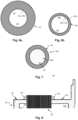
- FIG. 6a This is a cross section along line II of Fig. 5a . As can be seen from the Fig. 6a As can be seen, an outer peripheral surface 20c of the wick 20 can directly contact an entire peripheral surface defining the outlet opening 12.
- the outlet opening 12 can be completely filled or stuffed by the wick 20.
- the entire cross-sectional area of the outlet opening 12 is occupied by the wick 20 such that the liquid in the tank 10s flows through the outlet opening 12 only via the wick 20.
- the wick 20 is arranged in the outlet opening 12 and the guide 30 in such a way that the wick 20 covers the outlet opening 12 and/or the receiving space 30 of the guide 30 fills or completely fills.
- Fig. 6b which is a cross-section along the line II-II of the Fig. 5b the outer peripheral surface 20c of the wick 20 can directly contact an inner surface 30a of the peripheral wall 35 of the guide 30 at least over a lateral cross-section perpendicular to the longitudinal axis of the guide 30.
- the wick 20 occupies an entire volume or space of the receiving space 30s of the guide 30.
- the outlet opening 12 and/or the receiving space 30 of the guide 30 can be completely filled or stuffed by the wick 20.
- the wick 20 can be received in the outlet opening 12 and/or the receiving space 30s of the guide 30 by fitting it into the outlet opening 12 and/or the receiving space 30s of the guide 30.
- a sealing element 12s e.g., a rubber seal, as used, for example, in Figure 8 shown, be arranged at the outlet opening 12.
- the seal 12s may contact the outer peripheral surface 20c of the wick 20.
- the outlet end 22 of the wick 10 is not in direct contact with the second part 44 of the ultrasonic generator 40, as will be explained separately below.
- the device 1 can further comprise a holding element 60 (cf. Fig. 10 ) arranged between the mouthpiece 50 and the container 10.
- the ultrasonic generator 40 can be mounted on the support member 60 or received in the support member 60 to support, mount, or fix the ultrasonic generator 40 between the mouthpiece 50 and the container 10.
- the container may have a container connecting element 15 (as shown for example in Fig. 8 shown), and the holding element 60 may have a holding element connecting element (not shown).
- the container connecting element 15 and the holding element connecting element may correspond to each other and may engage with each other to fix or couple the container 10 and the holding element 60 with the ultrasonic generator 40 mounted thereon. This is shown in the Fig.9a and 9b
- the coupling can be detachable or reversible.
- Fig. 12 shows a further exemplary embodiment of the device 1, in which the wick 20 can be arranged directly in the tank 10s, ie in contact with the inner surface 10a of the tank 10s, and occupies the tank 10s - wholly or partially.
- the container 10 may have a guide segment 10g that defines the receiving space 30s.
- the wick 20 is arranged in the outlet opening 12 and the guide segment 10g such that the wick 20 fills or completely fills the outlet opening 12 and/or the receiving space 30s of the guide segment 10g.
- the guide segment 10g can absorb the liquid 3 adsorbed in the wick 20 arranged therein.
- the guide segment 10g can form the entire tank 10s.
- the container 10 may comprise a reservoir segment 10f in addition to the guide segment 10g.
- the reservoir segment 10f does not encompass the wick 20, i.e., it is not filled by the wick 20 and can hold the liquid 3 therein (cf. Fig. 12 ).
- the wick 20 can have a full length FL between 15 mm and 25 mm, for example 19 mm.
- a total length PL of the guide 30 and the outlet opening 12 can be between 12 mm and 18 mm, for example 16 mm.
- the wick 20 may comprise at least two sections or parts or segments - an inner section 24, i.e. a first section of the wick 20, which is arranged outside the outlet opening 12 and in the tank 10s, and an opening section 25, i.e. a second section, of the wick 20, which is arranged entirely in or inside the outlet opening 12, i.e. which does not protrude from the outlet opening 12 on any side.
- the wick 20 may optionally comprise a third section or part or segment - an outer section or an outer section 26 of the wick, which is arranged protruding from the outlet opening 12 to the outside of the container 10, i.e. arranged outside the tank 10s and outside the outlet opening 12.
- the wick 20 may protrude on both sides, i.e. the inlet end 21 of the wick 20 may protrude from the guide 30 into the tank 10s and the outlet end 22 of the wick 20 may protrude from the outlet opening 12 to an outside of the container 10 or the tank 10s.
- Fig. 15 The arrangement between the ultrasonic generator 40 and the outlet end 22 of the wick 20 is shown in the resting state of the ultrasonic generator 40. Due to the surface tension of the liquid 3, an accumulation of the liquid 3 forms as an arc-shaped drop on or at the outlet end 22 of the wick 20.
- the surface tension of the liquid 3 is selected to be sufficiently high or has a sufficiently high value that an accumulation of the liquid 3 forms as an arc-shaped drop on or at the outlet end 22 of the wick 20 (cf. Fig. 15 , Fig. 26 , Fig. 27 ).
- the invention ensures that any germ-inhibiting substances or other liquid components contained in the liquid 3 which prevent contamination of the aerosol generating device 1 do not reduce the surface tension of the liquid 3 to such an extent that there is no longer any accumulation of liquid 3 at the outlet end 22 of the wick 20.
- the outlet end 22 of the wick 20 has a distance of 90 (cf. Fig. 15 ) to the passages 44p formed in the second part 44 of the ultrasonic generator 40.
- This distance 90 can be achieved by stops, edges, spacer discs or spacer rings (not shown), or any other structural means for creating a distance.
- the Fig. 16 shows a partial view of the arrangement between the ultrasonic generator 40 and the outlet end 22 of the wick 20 while the second part 44 (with its passages 44p) is vibrated.
- the second part 44 of the ultrasonic generator 40 can be set into vibration by its first part 42.
- the passages 44p formed in the second part 44 touch or dip into the liquid 3 at the outlet end 22 of the wick 20, so that these passages 44p fill with the liquid 3. Due to the high frequency of the oscillations, the liquid 3 then emerges as an aerosol from the second part 44 of the ultrasonic generator 40 on its opposite side.
- the outlet end 22 of the wick 30 is exposed to an outer side of the outlet opening 12 and can either be flush with the outer surface 10b of the container 10 or protrude outwardly from the outer surface 10b of the container 10 or be arranged within the outlet opening 12.
- the outlet end 22 of the wick 20 is not in direct contact with the second part 44 of the ultrasonic generator 40.
- the outlet end 22 of the wick 20 is not in contact with the passages 44p or the mesh 44p formed in or by the second part 44 of the ultrasonic generator 40.
- the outlet end 22 of the wick 20 is not in direct contact with the second part 44 of the ultrasonic generator 40 at its receiving surface.
- the liquid 3 is supplied through the outlet end 22 of the wick and received by the receiving surface of the second part 44 of the ultrasonic generator 40.
- the first part 42 of the ultrasonic generator 40 oscillates by piezoelectric action and then implements or transmits the oscillations to the second part 44 of the ultrasonic generator 40, for example by it is in direct contact with the second part 44.
- the second part 44 of the ultrasonic generator 40 also oscillates.
- the liquid is taken up by the outlet end 22 of the wick 20 and suitably nebulized, and then at the opposite exit surface of the second part 44 as an aerosol 2 (cf. Fig. 10 ) into the aerosol chamber 50s and towards the outlet opening 50h of the mouthpiece 50.
- the generated aerosol 2 (cf. Fig. 10 ) then leaves the second part 44 of the ultrasonic generator 40 at or from the exit surface of the second part 44 of the ultrasonic generator 40, ie on its side opposite the wick 20.
- the surface tension of the liquid 3 is selected or set sufficiently high so that a collection of liquid 3 always forms at the outlet end 22 of the wick 20, opposite the ultrasonic generator 40 and its second part 44.
- this collection of liquid 3 serves, as explained, for transfer to the ultrasonic generator 40 and its second part 44, in particular when the latter is set into vibration during its actuation.
- the generated aerosol 2 is discharged from the exit surface of the second part 44 of the ultrasonic generator 40 into an aerosol chamber 50s (cf. Fig. 10 ) which is defined between the outlet opening 50h of the mouthpiece 50 and the ultrasonic generator 40, and then via the outlet opening 50h of the mouthpiece 50 to the outside of the device 1 or to the outside area A (cf. Fig. 17 ) of cartridge 9.
- Fig. 17 shows a further embodiment of the aerosol generating device 1 according to the invention, in which at least one flavored element 92 with a predetermined flavor is provided.
- a bypass 91 is formed within the mouthpiece 50, through which a fluid connection is formed between the aerosol chamber 50s of the mouthpiece 50 and an outer region A of the aerosol generating device 1 or the associated cartridge 9. Accordingly, during operation of the aerosol generating device 1, when a user exerts a suction force on or through the outlet opening 50h of the mouthpiece 50, fresh air is sucked in from outside and flows through the bypass 91 into the aerosol chamber 50s.
- the said flavored element 92 can be arranged on or in the mouthpiece 50, fluidically adjacent to the bypass 91, or directly within the bypass 91.
- the flavored element 92 is provided with a predetermined flavor, depending on the wishes of the respective user.
- the flavored element 92 is designed according to the invention with regard to its flavor such that an air flow, if it either flows past this flavored element 92 and/or flows through this element 92, absorbs flavor particles from or from the flavored elements 92, and the air flow then absorbs the respective flavor from the flavored element 92 together with the generated aerosol 2.
- the air flow enriched with the predetermined taste from the flavored element 92 is then drawn together with the aerosol 2, which has been generated by means of the vibration of the ultrasonic generator 40 (cf. the three points in Fig. 10 , with which the aerosol 2 is symbolized in a simplified manner within the aerosol chamber 50s), are directed together in the direction of the outlet opening 50h of the mouthpiece 50 and exits there from the mouthpiece 50 for inhalation by the user.
- the flavored element 92 is ring-shaped.
- the flavored element 92 should advantageously be located fluidically between the outlet opening 50h of the mouthpiece 50 and the bypass 91. Alternatively, it is also possible for the flavored element 92 to be located directly in the bypass 91 or adjacent thereto, e.g. at a (in Fig. 17 not shown) inlet opening of the bypass 91.
- a plurality of flavored elements 92 are attached to the mouthpiece.
- the flavored elements 92 can either be provided with the same flavor or with different flavors. In any case, with a plurality of flavored elements 92, it is understood that all of these elements 92 are then, as already explained, fluidically located between the outlet opening 50h of the mouthpiece 50 and the bypass 91. This ensures that the fresh air, which flows through the bypass 91 from the outer area A of the cartridge 9 or the mouthpiece 50 into its aerosol chamber 50s as a result of the suction generated by the user, always flows past the flavored elements 92 and/or flows through these elements 92, thereby taking on the flavor of the flavored elements 92.
- an aromatized element 92 can be easily replaced by the user, preferably without the use of a separate tool. This can be achieved in a simple manner if the cartridge 9 is disassembled from the main part 8 of the aerosol generating device 1 according to the invention (cf. Fig. 3 ), and/or if the mouthpiece 50 is removed from the container 10. Such an exchange possibility also applies, mutatis mutandis, to a plurality of flavored elements 9 that can be provided simultaneously on or in the mouthpiece 50.
- the above-mentioned replacement of the flavored element 92 is in the embodiment of Fig. 17 This is easily possible because, as explained, the flavored element 92 is ring-shaped. Thus, it can be easily inserted into or removed from the front of the mouthpiece 50 when the mouthpiece is removed from the container 10.
- Fig. 18 shows a front view of cartridge 9
- Fig. 19 a perspective view of cartridge 9 from below
- Fig. 20 a side view of cartridge 9.
- Fig. 21 shows a sectional view of cartridge 9 along line AA of Fig. 20 To clarify details of this sectional view, area I of Fig. 21 in the Fig. 21a shown enlarged. Similarly, area II of Fig. 21 in the Fig. 21b shown enlarged.
- a characteristic feature of the embodiment of the aerosol generating device 1 according to the invention of Fig. 21 consists in that the wick 20 is prestressed by a compression spring 46 along its longitudinal extent in the direction of the ultrasonic generator 40, such that the wick 20 is pressed with its outlet end 22 against the first part 42 of the ultrasonic generator 40.
- the wick 22 with its front side, on which its outlet end 22 is formed in contact with the first part 42 of the ultrasonic generator 40.
- the compression spring (46) is arranged in axial alignment with the wick (20) and rests against a lower end face of the wick (20), on which the inlet end 21 (see also Fig. 10 , in analogous consideration).
- the second part 44 of the ultrasonic generator 40 has a concave section 45 opposite the outlet end 22 of the wick.
- this concave section 45 it should be understood that the passages 44p of the second part 44 of the ultrasonic generator 40 are formed in this concave section 45.
- Fig. 21a shows the upper area of the wick 20 and the ultrasonic generator 40 arranged opposite it.
- Fig. 21a This shows the above-mentioned concave section 45 of the second part 44 of the ultrasonic generator 40, which, due to its curved shape, extends away from the wick 20.
- the functioning of the arrangement of Fig. 21a will be explained in more detail below.
- the inner region of the container 10 according to the embodiment of Fig. 21 is also based on the Fig. 23 shown, which is the sectional view of Fig. 21 now illustrated in perspective in a half section of the container 10.
- a guide sleeve 47 is provided, in which the wick 20 is enclosed along its longitudinal extent.
- a plurality of recesses 48 are formed within this guide sleeve 47. These recesses 48 serve the purpose of allowing the liquid stored in the tank 10s of the container 10 to flow radially through the recess(es) 48 toward the wick 20, to enter the individual capillaries of the wick 20 at the inlet end 21 and/or at other locations on the wick 20, and then to flow toward the outlet end 22 of the wick.
- Fig. 22 shows again - in disassembled state - the mouthpiece 50.
- this mouthpiece 50 can be attached to the container 10 at its front side, where the outlet opening 12 is located.
- Fig. 24 shows the ultrasonic generator 40 again in a perspective view.
- the ultrasonic generator 40 has a first annular part 42 (with a piezoelectric element not shown in detail), in the center of which the disc-shaped second Part 44 with the multitude of passes 44p (in Fig. 24 not shown for simplicity).
- suitable sealing elements are provided according to the invention, for example a seal receptacle 52 and a seal cover 54.
- the ultrasonic generator 40 is received in the manner of a "sandwich" between the seal receptacle 52 and the seal cover 54 and is suitably arranged together with these sealing elements 52, 54 in the outlet opening 12 or adjacent thereto.
- the ultrasonic generator 40 is shown with its first part 42 and its second part in a simplified side view. It can be seen that the second part 44 has the concave section 45 already mentioned above.
- Fig. 26 shows for the embodiment of Fig. 21 In principle, this simplifies the arrangement of the wick 20 when it is in contact with the second part 42 of the ultrasonic generator 40. As a result of the pretension exerted on the wick 20 by the compression spring 46, the wick 20 is pressed from below against the first part 42 of the ultrasonic generator 40.
- the embodiment functions according to Fig. 21 in the same way as the already explained embodiment of Fig. 15 and Fig. 16 : Even in the resting state of the ultrasonic generator 40, the liquid accumulates at or on the outlet end 22 of the wick 20 (cf. Fig. 26 ). If the ultrasonic generator 40 is now activated when the button 88 is pressed (see Fig.
- this second part 44 of the ultrasonic generator 44 when deformed downwards, ie in the direction of the wick 20, dips into the liquid 3 which has accumulated at the outlet end 22 of the wick 20, whereby the liquid 3 is then taken up in the passages 44p of the second part 44 of the ultrasonic generator 40.
- the present invention also provides a method for generating an aerosol 2.
- the aerosol 2 (cf. Fig. 10 , Fig. 28 ) can be generated by an aerosol generating device 1 according to the embodiment(s) explained above.
- a liquid 2 can be stored in the tank 10s of the container 10, wherein the thus stored liquid 3 is suitably aerosolized or nebulized, as explained, by actuating the ultrasonic generator 40 of the device 1.
- the liquid consists of water and ethanol.
- the amount of water can be equal to or greater than 80% by weight.
- substances or liquids which prevent contamination of the aerosol generating device 1 can reduce the surface tension of the liquid 3.
- a reduction in the surface tension can have an impact on the transport of the liquid 3 through the wick 20. If the surface tension of the liquid 3 is too low, an insufficient accumulation of the liquid 3 forms on the outlet end 22 of the wick 20.
- the liquid 3 is a water-based nicotine liquid, wherein other liquid components which prevent contamination of the aerosol generating device 1 do not reduce the surface tension of the liquid 3 to such an extent that an accumulation of liquid 3 no longer occurs at the outlet end 22 of the wick 20.
- this can be achieved by using the substances hydrogen peroxide, essential oils, silver ion solution and/or sodium chloride, which are contained in the liquid 3 and/or are suitably introduced into the wick 20.
- water-based liquid 3 for example, a food additive in the form of lactic acid.
- the desired pH value can be adjusted through all components of the water-based liquid 3.
- the pH value of the water-based liquid 3 should be adjusted to prevent corrosion at the passages 44p of the ultrasonic generator 40.
- the pH of liquid 3 can also be in the range between 4 and 8, and more preferably also in a range between 5 and 7. In other words, for the latter variant, the pH of liquid 3 is in the range 5-7.
- a nicotine lactate is formed.
Landscapes
- Health & Medical Sciences (AREA)
- Engineering & Computer Science (AREA)
- Anesthesiology (AREA)
- Biomedical Technology (AREA)
- Heart & Thoracic Surgery (AREA)
- Hematology (AREA)
- Life Sciences & Earth Sciences (AREA)
- Animal Behavior & Ethology (AREA)
- General Health & Medical Sciences (AREA)
- Public Health (AREA)
- Veterinary Medicine (AREA)
- Chemical & Material Sciences (AREA)
- Chemical Kinetics & Catalysis (AREA)
- General Chemical & Material Sciences (AREA)
- Bioinformatics & Cheminformatics (AREA)
- Pulmonology (AREA)
- Special Spraying Apparatus (AREA)
Abstract
Die Erfindung betrifft eine Aerosolerzeugungsvorrichtung und ein Verfahren zum Erzeugen eines Aerosols. Die Aerosolerzeugungsvorrichtung umfasst einen Behälter mit einem darin ausgebildeten Tank zum Speichern einer zu versprühenden Flüssigkeit (3). Der Behälter hat eine Auslassöffnung, einen Ultraschallgenerator (40), mittels dessen das Aerosol aus der Flüssigkeit (3) erzeugbar ist, ein an dem Behälter angrenzend zu dessen Auslassöffnung angebrachtes Mundstück, das eine Austrittsöffnung zum Freisetzen des von dem Ultraschallgenerator (40) erzeugten Aerosols aufweist, und einen in der Auslassöffnung des Behälters angeordneten Docht (20) zum Transport der Flüssigkeit (3) aus dem Tank zum Ultraschallgenerator (40). Der Ultraschallgenerator (40) umfasst einen ersten Teil (42) mit einem piezoelektrischen Element und einen zweiten Teil (44) mit einer Vielzahl von Durchgängen (44p), durch welche die Flüssigkeit (3) hindurchtreten kann. Hierbei ist das Auslassende (22) des Dochtes (20) so weit von dem zweiten Teil (44) des Ultraschallgenerators (40) beabstandet, dass der in Schwingung versetzte zweite Teil (44) mit der Vielzahl von Durchgängen (44p) nur die Flüssigkeit (3), die sich durch die Oberflächenspannung der selbigen Flüssigkeit (3) am Auslassende (22) des Dochts (20) angesammelt hat, berührt oder in diese Flüssigkeit (3) eintaucht und dadurch die Flüssigkeit (3) in den Durchgängen (44p) des zweiten Teils (44) des Ultraschallgenerators (40) aufgenommen wird.The invention relates to an aerosol generating device and a method for generating an aerosol. The aerosol generating device comprises a container with a tank formed therein for storing a liquid (3) to be sprayed. The container has an outlet opening, an ultrasonic generator (40) by means of which the aerosol can be generated from the liquid (3), a mouthpiece attached to the container adjacent to its outlet opening and having an outlet opening for releasing the aerosol generated by the ultrasonic generator (40), and a wick (20) arranged in the outlet opening of the container for transporting the liquid (3) from the tank to the ultrasonic generator (40). The ultrasonic generator (40) comprises a first part (42) with a piezoelectric element and a second part (44) with a plurality of passages (44p) through which the liquid (3) can pass. In this case, the outlet end (22) of the wick (20) is spaced so far from the second part (44) of the ultrasonic generator (40) that the vibrating second part (44) with the plurality of passages (44p) only touches the liquid (3) that has accumulated at the outlet end (22) of the wick (20) due to the surface tension of the same liquid (3) or is immersed in this liquid (3), and as a result the liquid (3) is absorbed in the passages (44p) of the second part (44) of the ultrasonic generator (40).
Description
Die Erfindung betrifft eine Aerosolerzeugungsvorrichtung zum Erzeugen eines Aerosols nach dem Oberbegriff von Anspruch 1, und ein Verfahren zum Erzeugen eines Aerosols.The invention relates to an aerosol generating device for generating an aerosol according to the preamble of
In den letzten Jahren hat sich die Verwendung von Aerosolen, die durch Nichtverbrennungstechniken erzeugt werden, immer mehr durchgesetzt. Elektrische Zigaretten (auch E-Zigaretten oder elektronische Zigaretten genannt) sind üblicherweise elektrisch beheizte Geräte zur Verdampfung eines Verbrauchsstoffs, insbesondere einer aromatisierten Flüssigkeit (auch Liquid genannt). Meist bestehen diese Geräte aus einem Tank, einem Verdampfer und einem Akkuträger. Bei den Tanksystemen unterscheidet man zwischen Cartomizer, Tröpfler, Clearomizer und Kartuschen. Beim Cartomizer ist die Heizwendel von einem als Flüssigkeitsspeicher dienenden Vliesstoff oder Watte umgeben. Ein Tröpfler ist technisch gesehen ein Cartomizer mit sehr geringem Aufnahmevolumen. Der Verbrauchsstoff wird hier vom Benutzer direkt auf die Dochte getropft, die zugleich als Flüssigkeitsspeicher dienen und muss nach wenigen Zügen erneut durch den Benutzer aufgebracht werden. Ein Clearomizer besteht aus einem Tank, in dem sich das Liquid frei vom Trägermaterial und abgekapselt vom Verdampfer befindet. Die vorstehend genannten Systeme haben alle gemeinsam, dass der Benutzer regelmäßig neuen Verbrauchsstoff nachfüllen muss. Bei Kartuschensystemen werden mit Liquid gefüllte Kartuschen in die E-Zigarette eingelegt. Die Verdampfungseinheit dient zum Verdampfen des Liquids. In der Regel findet in einem E-Zigaretten-Verdampfer kein Verbrennungsprozess statt, sondern eine Flüssigkeit gelangt insbesondere durch die Kapillarwirkung eines Dochtes von einem Tank zu einer Verdampfungseinheit, die meist als Heizwendel ausgebildet ist. Sobald der Benutzer durch Inhalieren einen Unterdruck innerhalb des Verdampfers erzeugt, wird die Verdampfungseinheit von einem Luftstrom umströmt, wobei das entstandene Aerosol durch die Sogwirkung vom Benutzer eingeatmet wird. Die Energieversorgung der Verdampfungseinheit erfolgt in der Regel über einen mit Akkus oder Batterien bestückten Akkuträger. Im Stand der Technik sind mehrere verschiedene Schnittstellen zur Verbindung eines Akkuträgers mit einem Verdampfer bekannt. Verdampfer der eingangs erwähnten Art sind in einer Vielzahl von unterschiedlichen Ausführungsformen bekannt.In recent years, the use of aerosols generated through non-combustion techniques has become increasingly popular. Electric cigarettes (also called e-cigarettes or electronic cigarettes) are typically electrically heated devices for vaporizing a consumable, particularly a flavored liquid (also called liquid). These devices usually consist of a tank, an atomizer, and a battery. Tank systems are divided into cartomizers, drippers, clearomizers, and cartridges. In a cartomizer, the heating coil is surrounded by a nonwoven fabric or cotton that serves as a liquid reservoir. A dripper is technically a cartomizer with a very small storage volume. The consumable is dripped directly onto the wicks by the user, which also serve as a liquid reservoir, and must be reapplied by the user after a few puffs. A clearomizer consists of a tank containing the liquid, free from the carrier material and encapsulated by the atomizer. All of the above-mentioned systems have in common that the user must regularly refill the consumable. With cartridge systems, cartridges filled with liquid are inserted into the e-cigarette. The vaporization unit is used to vaporize the liquid. Typically, no combustion process takes place in an e-cigarette vaporizer; instead, the liquid is drawn from a tank to a vaporization unit, usually designed as a heating coil, primarily through the capillary action of a wick. As soon as the user creates a vacuum within the vaporizer by inhaling, a stream of air flows around the vaporization unit, and the resulting aerosol is inhaled by the user due to the suction effect. The vaporization unit is usually powered by a rechargeable battery or batteries. Several different interfaces for connecting a battery pack to a vaporizer are known in the prior art. Vaporizers of the type mentioned above are known in a variety of different designs.
Die Benutzer passen sich an die Verwendung von Aerosolen an, die ohne Verbrennung erzeugt werden, um bekannte nachteilige Auswirkungen der Verbrennung zu vermeiden, wie z. B. bei herkömmlichen Zigaretten, bei denen ein Ende angezündet wird, um Tabak oder andere Inhaltsstoffe zu verbrennen, um Rauch zu erzeugen. Aerosolgeneratoren ohne Verbrennung, auch als persönliche Verdampfer, Inhalatoren und E-Zigaretten bezeichnet, werden immer beliebter. Solche Aerosolgeneratoren verwenden elektrische Heiz- oder Ultraschalltechniken, um eine im Inneren des Aerosolgenerators gespeicherte Flüssigkeit zu aerosolisieren.Users are adapting to the use of aerosols generated without combustion to avoid the known adverse effects of combustion, such as those found in traditional cigarettes, where one end is lit to burn tobacco or other ingredients to produce smoke. Non-combustion aerosol generators, also known as personal vaporizers, inhalers, and e-cigarettes, are becoming increasingly popular. Such aerosol generators use electrical heating or ultrasonic techniques to aerosolize a liquid stored inside the aerosol generator.
Ein wesentlicher Nachteil dieser vorbekannten Verdampfer besteht insbesondere darin, dass nach dem Inhalieren beim Ausatmen die Umgebung mit Restmengen des verdampften Liquids belastet wird.A major disadvantage of these previously known vaporizers is that after inhalation, the environment is polluted with residual amounts of the vaporized liquid when exhaling.
Bei der Ultraschalltechnik, die z.B aus
Bei diesem Stand der Technik liegt ein Docht direkt (oder mittelbar, vgl.
Ein ähnliches Problem entsteht, wenn Flüssigkeit durch Kapillarwirkung aus dem Aerosolgenerator in Richtung des Ultraschallgenerators austritt und sich auf dem Ultraschallgenerator, insbesondere auf einer Oberseite des Ultraschallgenerators, absetzt. Flüssigkeiten, insbesondere wasserbasierte Flüssigkeiten, die aufgrund der Kapillarwirkung in den Öffnungen des Ultraschallelementes verbleiben, verursachen Korrosion durch ihren PH-Wert an dem Ultraschallelement.A similar problem arises when liquid leaks from the aerosol generator toward the ultrasonic generator due to capillary action and deposits on the ultrasonic generator, particularly on the top surface of the ultrasonic generator. Liquids, especially water-based liquids, that remain in the openings of the ultrasonic element due to capillary action cause corrosion of the ultrasonic element due to their pH value.
Die Verkeimung eines solchen Aerosolgenerators unter Verwendung einer wasserbasierten Flüssigkeit ist ebenfalls ein sehr großes Problem, die zwingend zu unterbinden ist. Hierzu werden diese Flüssigkeiten z.B. durch die Zugabe von Alkohol so angepasst, dass eine Verkeimung verhindert wird. Die Zugabe solcher Stoffe wie z.B. Alkohol verringert aber die Oberflächenspannung von Wasser. Die Oberflächenspannung einer Flüssigkeit betrifft die Grenzfläche zwischen der Flüssigkeit und der Luft. Sie entsteht aufgrund der Anziehungskräfte zwischen den Molekülen der Flüssigkeit an der Oberfläche. Alkoholmoleküle haben eine geringere Anziehungskraft als Wassermoleküle, wodurch sie die Anziehungskräfte an der Oberfläche von Wasser stören können. Wenn Alkohol zu Wasser hinzugefügt wird, verringert dies die Oberflächenspannung, da die Alkoholmoleküle zwischen den Wassermolekülen platziert werden und die Anziehungskräfte abschwächen.The contamination of such an aerosol generator using a water-based liquid is also a very serious problem that must be prevented at all costs. To this end, these liquids are modified, for example, by adding alcohol to prevent contamination. However, the addition of substances such as alcohol reduces the surface tension of water. The surface tension of a liquid affects the interface between the liquid and the air. It arises due to the attractive forces between the liquid molecules at the surface. Alcohol molecules have a weaker attractive force than water molecules, which means they can disrupt the attractive forces at the surface of the water. Adding alcohol to water reduces the surface tension because the alcohol molecules are placed between the water molecules, weakening the attractive forces.
Aufgrund eines oder mehrerer der oben genannten Probleme kommt es zum einen zu einer gestörten Aerosolerzeugung und zum anderen zu einer Verzögerung bei der Aerosolerzeugung. Hierbei ist es erforderlich, das Gerät zu schütteln oder zu schlagen, um die Tröpfchen vom Ultraschallgenerator abzuschlagen und die Aerosolerzeugung zu unterstützen. Ist die Korrosion stark fortgeschritten, ist die Funktion des Ultraschallgenerators nicht mehr gewährleistet.Due to one or more of the problems mentioned above, either impaired aerosol generation or a delay in aerosol generation occurs. Shaking or striking the device is necessary to knock the droplets off the ultrasonic generator and assist aerosol generation. If the corrosion is severe, the function of the ultrasonic generator is no longer guaranteed.
Die oben genannten Probleme der Verdampfung und Kondensation und/oder Leckage werden noch verschärft, wenn die in dem Aerosolgenerator gespeicherte Flüssigkeit Komponenten wie Wasser enthält.The above-mentioned problems of evaporation and condensation and/or leakage are further exacerbated when the liquid stored in the aerosol generator contains components such as water.
Somit ist eine Technik zur Erzeugung von Aerosol erwünscht, die einen oder mehrere der oben genannten Nachteile verringert oder vermeidet.Thus, an aerosol generation technique is desired that reduces or avoids one or more of the above-mentioned disadvantages.
Entsprechend liegt der Erfindung die Aufgabe zugrunde, den Betrieb einer Aerosolerzeugungsvorrichtung und eines Verfahrens zum Erzeugen von Aerosol hinsichtlich der Aerosolbildung zu optimieren.Accordingly, the invention is based on the object of optimizing the operation of an aerosol generating device and a method for generating aerosol with regard to aerosol formation.
Die obige Aufgabe wird durch eine Vorrichtung mit den Merkmalen von Anspruch 1, und durch ein Verfahren mit den Merkmalen nach Anspruch 10 gelöst. Vorteilhafte Weiterbildungen der Erfindung sind Gegenstand der abhängigen Ansprüche.The above object is achieved by a device having the features of
Eine Aerosolerzeugungsvorrichtung zum Erzeugen eines Aerosols gemäß der vorliegenden Erfindung kann ein persönlicher Verdampfer, ein Inhalator, eine elektrische Zigarette oder eine E-Zigarette sein. Die Aerosolerzeugungsvorrichtung kann eine tragbare und/oder eine Vorrichtung im Taschenformat sein. Die Aerosolerzeugungsvorrichtung (im Folgenden auch als Aerosolgenerator oder einfach als Vorrichtung bezeichnet) umfasst einen Behälter (auch als Reservoir bezeichnet), einen Docht (auch als Kapillarelement bezeichnet), einen Ultraschallgenerator (auch als Ultraschallsonde, Wandler, Aktor bezeichnet) und ein Mundstück.An aerosol generating device for generating an aerosol according to the present invention may be a personal vaporizer, an inhaler, an electronic cigarette, or an e-cigarette. The aerosol generating device may be a portable and/or pocket-sized device. The aerosol generating device (hereinafter also referred to as an aerosol generator or simply a device) comprises a container (also referred to as a reservoir), a wick (also referred to as a capillary element), an ultrasonic generator (also referred to as an ultrasonic probe, transducer, actuator), and a mouthpiece.
Eine Aerosolerzeugungsvorrichtung gemäß der vorliegenden Erfindung dient zum Erzeugen eines Aerosols, und umfasst einen Behälter mit einem darin ausgebildeten Tank zum Speichern einer zu versprühenden Flüssigkeit, wobei der Behälter aufweist: eine Auslassöffnung, einen Ultraschallgenerator, mittels dessen das Aerosol aus der Flüssigkeit erzeugbar ist, ein an dem Behälter angrenzend zu dessen Auslassöffnung angebrachtes Mundstück, das eine Austrittsöffnung zum Freisetzen des von dem Ultraschallgenerator erzeugten Aerosols aufweist, und einen in der Auslassöffnung des Behälters angeordneten Docht zum Transport der Flüssigkeit aus dem Tank zum Ultraschallgenerator, wobei der Docht ein im Inneren des Tanks angeordnetes Einlassende zur Aufnahme der in dem Tank gespeicherten Flüssigkeit und ein angrenzend zum Ultraschallgenerator angeordnetes Auslassende zur Bereitstellung der Flüssigkeit für den Ultraschallgenerator aufweist. Der Ultraschallgenerator ist zwischen der Austrittsöffnung des Mundstücks und dem Docht angeordnet ist. Der Ultraschallgenerator umfasst einen ersten Teil mit einem piezoelektrischen Element und einen zweiten Teil mit einer Vielzahl von Durchgängen, durch welche die Flüssigkeit hindurchtreten kann. Das Auslassende des Dochtes ist so weit von dem zweiten Teil des Ultraschallgenerators beabstandet, dass der in Schwingung versetzte zweite Teil mit der Vielzahl von Durchgängen nur die Flüssigkeit, die sich durch die Oberflächenspannung der selbigen Flüssigkeit am Auslassende des Dochts angesammelt hat, berührt oder in diese Flüssigkeit eintaucht und dadurch die Flüssigkeit in den Durchgängen des zweiten Teils des Ultraschallgenerators aufgenommen wird.An aerosol generating device according to the present invention is used to generate an aerosol and comprises a container with a tank formed therein for storing a liquid to be sprayed, the container having: an outlet opening, an ultrasonic generator, by means of which the aerosol can be generated from the liquid, a mouthpiece attached to the container adjacent to its outlet opening, which mouthpiece has an outlet opening for releasing the aerosol generated by the ultrasonic generator, and a wick arranged in the outlet opening of the container for transporting the liquid from the tank to the ultrasonic generator, the wick having a An inlet end arranged inside the tank for receiving the liquid stored in the tank and an outlet end arranged adjacent to the ultrasonic generator for providing the liquid to the ultrasonic generator. The ultrasonic generator is arranged between the outlet opening of the mouthpiece and the wick. The ultrasonic generator comprises a first part with a piezoelectric element and a second part with a plurality of passages through which the liquid can pass. The outlet end of the wick is spaced far enough from the second part of the ultrasonic generator that the vibrating second part with the plurality of passages only contacts the liquid that has collected at the outlet end of the wick due to the surface tension of the same liquid, or is immersed in this liquid, and the liquid is thereby absorbed into the passages of the second part of the ultrasonic generator.
Der vorliegenden Erfindung liegt die wesentliche Erkenntnis zugrunde, dass das Auslassende des Dochtes so weit von dem Ultraschallgenerator beabstandet ist, dass dessen zweiter Teil, der zum Erzeugen eines Aerosols erfindungsgemäß in Schwingung versetzt wird, den Docht an seinem Auslassende nicht direkt berüht bzw. damit in Kontakt steht. Hierdurch wird der Vorteil erreicht, dass im Betrieb der Aerosolerzeugungsvorrichtung die Schwingung des zweiten Teils des Ultraschallgenerators nicht durch eine Berührung mit dem Docht beeinflusst bzw. beeinträchtigt wird. Anders ausgedrückt, kann der zweite Teil des Ultraschallgenerators, in dem die Vielzahl von Durchgängen ausgebildet ist, beabstandet zum Docht und somit ungehindert vom Docht in Schwingung versetzt werden. Hierbei ist die Aufnahme von Flüssigkeit, die sich bedingt durch deren Oberflächenspannung an der Auslassöffnung des Dochtes angesammelt hat, dadurch gewährleistet, dass der zweite Teil des Ultraschallgenerators, wenn er in Schwingung versetzt und dabei in Richtung des Dochts verformt wird, dann in diese Ansammlung von Flüssigkeit eintaucht und dadurch die Flüssigkeit in den Durchgängen des zweiten Teils des Ultraschallgenerators aufgenommen wird. Hier tritt dann die Flüssigkeit durch die Durchgänge des zweiten Teils des Ultraschallgenerators zur entgegensetzten Seite des zweiten Teils hindurch, wobei dann bei fortgesetzter Schwingung des zweiten Teils die Flüssigkeit aus den Durchgängen nach außen herausgeschleudert und sich hierdurch das gewünschte Aerosol erzeugt wird.The present invention is based on the essential finding that the outlet end of the wick is spaced far enough from the ultrasonic generator that its second part, which is set into vibration according to the invention to generate an aerosol, does not directly touch or is in contact with the wick at its outlet end. This has the advantage that, during operation of the aerosol generating device, the vibration of the second part of the ultrasonic generator is not influenced or impaired by contact with the wick. In other words, the second part of the ultrasonic generator, in which the plurality of passages is formed, can be set into vibration at a distance from the wick and thus unhindered by the wick. The absorption of liquid that has accumulated at the outlet opening of the wick due to its surface tension is ensured in that the second part of the ultrasonic generator, when set into vibration and thereby deformed in the direction of the wick, then immerses itself in this accumulation of liquid, and the liquid is thereby absorbed in the passages of the second part of the ultrasonic generator. Here the liquid then passes through the passages of the second part of the ultrasonic generator to the opposite side of the second part, whereby with continued vibration of the second part the liquid from the passages are thrown outwards, thereby creating the desired aerosol.
Gemäß einer vorteilhaften Weiterbildung der Erfindung kann vorgesehen sein, dass der zweite Teil des Ultraschallgenerators gegenüber dem Auslassende des Dochts gesehen einen konkaven Abschnitt aufweist, wobei die Durchgänge des zweiten Teils des Ultraschallgenerators in dem konkaven Abschnitt ausgebildet sind. Bedingt durch den besagten konkaven Abschnitt ist erfindungsgemäß gewährleistet, dass der zweite Teil des Ultraschallgenerators, sowohl in Ruhestellung als auch insbesondere in seinem Schwingungszustand, stets ausreichend weit von dem Docht und dessen Auslassende beabstandet ist, so dass die Schwingung des zweiten Teils des Ultraschallgenerators nicht durch eine Berührung mit dem Docht beeinträchtigt wird.According to an advantageous development of the invention, the second part of the ultrasonic generator can have a concave section opposite the outlet end of the wick, with the passages of the second part of the ultrasonic generator being formed in the concave section. Due to said concave section, the invention ensures that the second part of the ultrasonic generator, both in the rest position and particularly in its oscillating state, is always sufficiently far away from the wick and its outlet end so that the oscillation of the second part of the ultrasonic generator is not impaired by contact with the wick.
Die vorliegende Erfindung sieht ebenfalls ein Verfahren zum Erzeugen eines Aerosols unter Verwendung einer Aerosolerzeugungsvorrichtung mit einem Docht vor, wobei es sich bei dieser Aerosolerzeugungsvorrichtung um die vorstehend genannte erfindungsgemäße Vorrichtung handeln kann. Jedenfalls ist bei dem erfindungsgemäßen Verfahren vorgesehen, dass eine Flüssigkeit, mit der das Aerosol erzeugt wird, eine wasserbasierte Nikotinflüssigkeit ist, wobei die Flüssigkeit eine Oberflächenspannung hat, mit der sich an dem Auslassende des Dochtes eine Ansammlung von Flüssigkeit zur Übergabe an den Ultraschallgenerator bildet.The present invention also provides a method for generating an aerosol using an aerosol generating device with a wick, which aerosol generating device may be the aforementioned device according to the invention. In any case, the method according to the invention provides that a liquid used to generate the aerosol is a water-based nicotine liquid, the liquid having a surface tension that forms a pool of liquid at the outlet end of the wick for transfer to the ultrasonic generator.
Gemäß einer vorteilhaften Weiterbildung der Erfindung kann die Flüssigkeit verkeimungshemmende Stoffe enthalten. Erfindungsgemäß ist das Merkmal "verkeimungshemmende Stoffe" dahingehend zu verstehen, dass es sich hierbei um zumindest einen solchen Stoff bzw. eine Substanz handeln kann, mit dem bzw. der eine Verkeimung zumindest gehemmt oder gar verhindert wird.According to an advantageous development of the invention, the liquid can contain antimicrobial substances. According to the invention, the term "antimicrobial substances" is to be understood to mean that this can be at least one substance that at least inhibits or even prevents the growth of microbes.
Bei dem vorstehend genannten Verfahren gemäß der vorliegenden Erfindung besteht ein charakteristisches Merkmal darin, dass die Flüssigkeit eine wasserbasierte Nikotinflüssigkeit, wobei andere Flüssigkeitsanteile, die ggf. eine Verkeimung der Aerosolerzeugungsvorrichtung verhindern, die Oberflächenspannung der Flüssigkeit nicht so weit reduzieren, dass es nicht mehr zu einer Ansammlung von Flüssigkeit an dem Auslassende des Dochtes kommt.In the above-mentioned method according to the present invention, a characteristic feature is that the liquid is a water-based nicotine liquid, with other liquid components, which may prevent contamination of the aerosol generating device, the surface tension the liquid to such an extent that there is no longer an accumulation of liquid at the outlet end of the wick.
Gemäß einer vorteilhaften Weiterbildung der Erfindung ist in der Flüssigkeit als verkeimungshemmender Stoff zumindest eine Substanz gebildet aus der Gruppe Wasserstoffperoxid, ätherische Öle, Silberionen-Lösung und Natriumchlorid enthalten. Vorzugsweise kann in der Flüssigkeit eine Kombination von Substanzen gebildet aus der Gruppe von Wasserstoffperoxid, ätherische Öle, Silberionen-Lösung und/oder Natriumchlorid enthalten sein.According to an advantageous development of the invention, the liquid contains at least one substance selected from the group consisting of hydrogen peroxide, essential oils, silver ion solution, and sodium chloride as a germ-inhibiting substance. Preferably, the liquid can contain a combination of substances selected from the group consisting of hydrogen peroxide, essential oils, silver ion solution, and/or sodium chloride.
Eine erfindungsgemäße Aerosolerzeugungsvorrichtung gemäß einer weiteren Ausführungsform, der eine eigenständige Bedeutung zukommt, umfasst einen Behälter mit einem darin ausgebildeten Tank zum Speichern einer zu versprühenden Flüssigkeit, wobei der Behälter aufweist: eine Auslassöffnung, einen Ultraschallgenerator, mittels dessen das Aerosol aus der Flüssigkeit erzeugbar ist, ein an dem Behälter angrenzend zu dessen Auslassöffnung angebrachtes Mundstück, das eine Austrittsöffnung zum Freisetzen des von dem Ultraschallgenerator erzeugten Aerosols aufweist, und einen in der Auslassöffnung des Behälters angeordneten Docht zum Transport der Flüssigkeit aus dem Tank zum Ultraschallgenerator, wobei der Docht ein im Inneren des Tanks angeordnetes Einlassende zur Aufnahme der in dem Tank gespeicherten Flüssigkeit und ein angrenzend zum Ultraschallgenerator angeordnetes Auslassende zur Bereitstellung der Flüssigkeit für den Ultraschallgenerator aufweist. Der Ultraschallgenerator ist zwischen der Austrittsöffnung des Mundstücks und dem Docht angeordnet ist. Charakteristische Merkmale der Erfindung bestehen darin, dass die Flüssigkeit eine wasserbasierte Nikotinflüssigkeit ist, dass die Flüssigkeit verkeimungshemmende Stoffe enthält, und dass die Flüssigkeit eine Oberflächenspannung hat, mit der sich an dem Auslassende des Dochtes eine Ansammlung von Flüssigkeit zur Übergabe an den Ultraschallgenerator bildet.An aerosol generating device according to the invention according to a further embodiment, which has independent significance, comprises a container with a tank formed therein for storing a liquid to be sprayed, wherein the container has: an outlet opening, an ultrasonic generator, by means of which the aerosol can be generated from the liquid, a mouthpiece attached to the container adjacent to its outlet opening, which mouthpiece has an outlet opening for releasing the aerosol generated by the ultrasonic generator, and a wick arranged in the outlet opening of the container for transporting the liquid from the tank to the ultrasonic generator, wherein the wick has an inlet end arranged inside the tank for receiving the liquid stored in the tank and an outlet end arranged adjacent to the ultrasonic generator for providing the liquid to the ultrasonic generator. The ultrasonic generator is arranged between the outlet opening of the mouthpiece and the wick. Characteristic features of the invention are that the liquid is a water-based nicotine liquid, that the liquid contains antimicrobial substances, and that the liquid has a surface tension with which a collection of liquid forms at the outlet end of the wick for transfer to the ultrasonic generator.
Gemäß einer vorteilhaften Weiterbildung der Erfindung können die besagten verkeimungshemmenden Stoffe bzw. anderen Flüssigkeitsanteile, mit denen u.a. die gewünschte Verhinderung einer Verkeimung erreicht wird, folgende Substanzen enthalten oder hieraus gebildet sein:
- Wasserstoffperoxid: Diese Substanz wirkt oxidierend und kann Mikroorganismen effektiv abtöten; und/oder
- Ätherische Öle: Einige Öle, wie Teebaumöl, haben natürliche antimikrobielle Eigenschaften; und/oder
- Silberionen-Lösungen: Silber hat die Eigenschaft eines antimikrobiellen Mittels und leistet somit ebenfalls einen Beitrag zur Verhinderung einer Verkeimung; und/oder:
- Natriumchlorid: Diese Substanz hat ebenfalls eine konservierende Eigenschaft und kann dazu beitragen, eine Verkeimung zu verhindern.
- Hydrogen peroxide: This substance has an oxidizing effect and can effectively kill microorganisms; and/or
- Essential oils: Some oils, such as tea tree oil, have natural antimicrobial properties; and/or
- Silver ion solutions: Silver has the property of an antimicrobial agent and thus also contributes to the prevention of microbial contamination; and/or:
- Sodium chloride: This substance also has a preservative property and can help prevent contamination.
Gemäß einer vorteilhaften Weiterbildung der Erfindung kann vorgesehen sein, dass die Flüssigkeit Nikotin in einer Menge enthält, die aus einem Bereich von 0,05 mg/ml bis 20 mg/ml gewählt ist.According to an advantageous development of the invention, it can be provided that the liquid contains nicotine in an amount selected from a range of 0.05 mg/ml to 20 mg/ml.
Gemäß einer vorteilhaften Weiterbildung der Erfindung kann vorgesehen sein, dass die Flüssigkeit Natriumchlorid in einer Menge von 0,5 bis 3 Gewichtsprozent bezogen auf den Anteil von Wasser enthält. Zweckmäßigerweise kann die Flüssigkeit 0,9 Gewichtsprozent Natriumchlorid (bezogen auf den Anteil von Wasser) enthalten. Erfindungsgemäß hat Natriumchlorid zwei Auswirkungen auf die Eigenschaft der zu vernebelnden Flüssigkeit: Es hat einerseits konservierende Eigenschaften und kann wie bereits erläutert dazu beitragen, eine Verkeimung zu verhindern. Des Weiteren wird mit Natriumchlorid auch die Oberflächenspannung der Flüssigkeit vorteilhaft erhöht. Damit kommt es beispielsweise an dem Auslassende des Dochts in gewünschter Weise zu einer Ansammlung von Flüssigkeit, die dann von dem Ultraschallgenerator, wenn dieser in Schwingung versetzt wird, geeignet aufgenommen und aerosolisiert bzw. vernebelt wird.According to an advantageous development of the invention, the liquid can contain sodium chloride in an amount of 0.5 to 3 percent by weight, based on the proportion of water. The liquid can expediently contain 0.9 percent by weight of sodium chloride (based on the proportion of water). According to the invention, sodium chloride has two effects on the properties of the liquid to be nebulized: On the one hand, it has preservative properties and, as already explained, can help prevent microbial contamination. Furthermore, sodium chloride also advantageously increases the surface tension of the liquid. This leads, for example, to a desired accumulation of liquid at the outlet end of the wick, which is then suitably absorbed and aerosolized or nebulized by the ultrasonic generator when it is set into vibration.
Im Sinne der vorliegenden Erfindung versteht sich, dass die vorstehend genannten Substanzen in der Flüssigkeit entweder alleine oder in einer Kombination hiervon enthalten sein können, jeweils in verschiedenen geeigneten Konzentrationen.For the purposes of the present invention, it is understood that the above-mentioned substances can be contained in the liquid either alone or in a combination thereof, in each case in various suitable concentrations.
Gemäß einer vorteilhaften Weiterbildung der Erfindung kann vorgesehen sein, dass die Flüssigkeit enthält: 85 Volumenprozent Wasser, 15 Volumenprozent Ethanol, 0,5 mg/ml Nikotin, 0,9 Gewichtsprozent Natriumchlorid (bezogen auf den Anteil von Wasser).According to an advantageous development of the invention, it can be provided that the liquid contains: 85% by volume water, 15% by volume ethanol, 0.5 mg/ml nicotine, 0.9% by weight sodium chloride (based on the proportion of water).
Gemäß einer vorteilhaften Weiterbildung der Erfindung kann vorgesehen sein, dass in den Docht der Vorrichtung zumindest eine Substanz gebildet aus der Gruppe Wasserstoffperoxid, ätherische Öle, Silberionen-Lösung und Natriumchlorid eingebracht ist, vorzugsweise, dass in den Docht eine Kombination von Substanzen gebildet aus der Gruppe von Wasserstoffperoxid, ätherische Öle, Silberionen-Lösung und/oder Natriumchlorid eingebracht ist. In Folge eines Durchströmens des Dochts nimmt dann die Flüssigkeit die Substanz(en), die in den Docht zuvor eingebracht worden ist bzw. sind, bei einem Durchströmen des Dochts auf, so dass damit dann diese Substanzen in der Flüssigkeit gelöst bzw. aufgenommen werden und beispielsweise die vorstehend genannte Wirkung zwecks der Verhinderung einer Verkeimung ausüben.According to an advantageous development of the invention, it can be provided that at least one substance selected from the group consisting of hydrogen peroxide, essential oils, silver ion solution, and sodium chloride is introduced into the wick of the device, preferably that a combination of substances selected from the group consisting of hydrogen peroxide, essential oils, silver ion solution, and/or sodium chloride is introduced into the wick. As a result of the liquid flowing through the wick, it absorbs the substance(s) previously introduced into the wick as it flows through the wick, so that these substances are then dissolved or absorbed in the liquid and, for example, exert the aforementioned effect of preventing germs.
Für die vorstehend erwähnte Variante der Erfindung, wonach zumindest eine der genannten Substanzen geeignet in den Docht eingebracht ist, ist erfindungsgemäß zu verstehen, dass es hierbei dann möglich ist, dass diese Substanz (oder vorzugsweise alle dieser Substanzen, falls es mehrere sind), falls der Docht in Folge seiner Kapillarwirkung oder Dochtwirkung von der Flüssigkeit durchströmt wird, dann an die Flüssigkeit abgegeben wird.For the above-mentioned variant of the invention, according to which at least one of the substances mentioned is suitably introduced into the wick, it is to be understood according to the invention that it is then possible for this substance (or preferably all of these substances, if there are several), to be released into the liquid if the wick is flowed through by the liquid as a result of its capillary action or wicking action.
Eine erfindungsgemäße Aerosolerzeugungsvorrichtung gemäß einer weiteren Ausführungsform, der eine eigenständige Bedeutung zukommt, umfasst einen Behälter mit einem darin ausgebildeten Tank zum Speichern einer zu versprühenden Flüssigkeit, wobei der Behälter eine Auslassöffnung aufweist, einen Ultraschallgenerator, mittels dessen das Aerosol aus der Flüssigkeit erzeugbar ist, ein an dem Behälter angrenzend zu dessen Auslassöffnung angebrachtes Mundstück, das eine Austrittsöffnung zum Freisetzen des von dem Ultraschallgenerator erzeugten Aerosols aufweist, und einen in der Auslassöffnung des Behälters angeordneten Docht zum Transport der Flüssigkeit aus dem Tank zum Ultraschallgenerator, wobei der Docht ein im Inneren des Tanks angeordnetes Einlassende zur Aufnahme der in dem Tank gespeicherten Flüssigkeit und ein angrenzend zum Ultraschallgenerator angeordnetes Auslassende zur Bereitstellung der Flüssigkeit für den Ultraschallgenerator aufweist. Der Ultraschallgenerator ist zwischen der Austrittsöffnung des Mundstücks und dem Docht angeordnet ist. In dem Mundstück ist eine Aerosolkammer ausgebildet, die sich zwischen der Austrittsöffnung des Mundstücks und dem Ultraschallgenerator befindet, so dass das vom Ultraschallgenerator erzeugte Aerosol in die Aerosolkammer abgegeben wird. Des Weiteren ist an oder in dem Mundstück zumindest ein Bypass ausgebildet, durch den eine Fluidverbindung zwischen der Aerosolkammer und einem Außenbereich des Mundstücks gebildet ist, wobei zumindest ein aromatisiertes Element mit einer vorbestimmten Geschmacksrichtung an dem Mundstück strömungstechnisch zwischen der Austrittsöffnung und dem Bypass des Mundstücks angeordnet ist.An aerosol generating device according to the invention according to a further embodiment, which has an independent significance, comprises a container with a tank formed therein for storing a liquid to be sprayed, wherein the container has an outlet opening, an ultrasonic generator, by means of which the aerosol can be generated from the liquid, a mouthpiece attached to the container adjacent to its outlet opening, which mouthpiece has an outlet opening for releasing the aerosol generated by the ultrasonic generator, and a wick arranged in the outlet opening of the container for transporting the liquid from the tank to the Ultrasonic generator, wherein the wick has an inlet end arranged inside the tank for receiving the liquid stored in the tank and an outlet end arranged adjacent to the ultrasonic generator for providing the liquid to the ultrasonic generator. The ultrasonic generator is arranged between the outlet opening of the mouthpiece and the wick. An aerosol chamber is formed in the mouthpiece, which is located between the outlet opening of the mouthpiece and the ultrasonic generator, so that the aerosol generated by the ultrasonic generator is released into the aerosol chamber. Furthermore, at least one bypass is formed on or in the mouthpiece, through which a fluid connection is formed between the aerosol chamber and an outer region of the mouthpiece, wherein at least one flavored element with a predetermined flavor is arranged on the mouthpiece fluidically between the outlet opening and the bypass of the mouthpiece.
Gemäß einer weiteren Ausführungsform der vorliegenden Erfindung, der eine eigenständige Bedeutung zukommt, ist auch ein Verfahren zum Erzeugen eines Aerosols unter Verwendung einer Aerosolerzeugungsvorrichtung mit einem Mundstück vorgesehen, wobei es sich bei hierbei verwendeten Aerosolerzeugungsvorrichtung um eine der vorstehend genannte erfindungsgemäßen Vorrichtungen handeln kann. Jedenfalls ist bei dem erfindungsgemäßen Verfahren vorgesehen, dass zusammen mit der Aerosolerzeugungsvorrichtung zumindest ein insbesondere austauschbares aromatisiertes Element mit einer vorbestimmten Geschmacksrichtung bereitgestellt und an dem Mundstück angebracht wird, derart, dass eine Luftströmung, die vom Anwender zusammen mit dem erzeugten Aerosol inhaliert wird, vor einer Inhalation durch den Anwender an dem aromatisierten Element vorbeiströmt und/oder durch das aromatisierte Element hindurchströmt und dadurch die Luftströmung zusammen mit dem erzeugten Aerosol die vorbestimmte Geschmacksrichtung des aromatisierte Elements annimmt.According to a further embodiment of the present invention, which is of independent significance, a method for generating an aerosol using an aerosol generating device with a mouthpiece is also provided, wherein the aerosol generating device used here can be one of the aforementioned devices according to the invention. In any case, the method according to the invention provides that, together with the aerosol generating device, at least one, in particular replaceable, flavored element with a predetermined flavor is provided and attached to the mouthpiece in such a way that an air flow inhaled by the user together with the generated aerosol flows past the flavored element and/or through the flavored element before inhalation by the user, and thereby the air flow together with the generated aerosol takes on the predetermined flavor of the flavored element.
Der zuletzt genannten Ausführungsform der Erfindung liegt die wesentliche Erkenntnis zugrunde, dass es mittels eines aromatisierten Elements, welches über eine vorbestimmte Geschmacksrichtung verfügt, in einfacher Weise möglich ist, dem erzeugten Aerosol diese vorbestimmte Geschmacksrichtung zu verleihen bzw. hinzuzufügen. Dies kann erfindungsgemäß in einfacher Weise dadurch erreicht werden, dass das besagte aromatisierte Element mit der vorbestimmten Geschmacksrichtung an dem Mundstück der Aerosolerzeugungsvorrichtung, welche Gegenstand der vorliegenden Erfindung ist oder zur Durchführung des erfindungsgemäßen Verfahrens eingesetzt wird, angebracht wird. Durch den Bypass, der an oder in dem Mundstück ausgebildet ist, wird dann erreicht, dass der Anwender beim Inhalieren des erzeugten Aerosols stets auch Frischluft von außerhalb des Mundstücks mitansaugt, wobei diese Frischluft dabei an dem aromatisierten Element vorbeiströmt und/oder durch das aromatisierte Element hindurchströmt und dadurch die Luftströmung zusammen mit dem erzeugten Aerosol die vorbestimmte Geschmacksrichtung des aromatisierten Elements annimmt.The last-mentioned embodiment of the invention is based on the essential finding that by means of an aromatized element which has a predetermined flavor, it is possible in a simple manner is to impart or add this predetermined flavor to the generated aerosol. This can be achieved in a simple manner according to the invention by attaching the said flavored element with the predetermined flavor to the mouthpiece of the aerosol generating device which is the subject of the present invention or is used to carry out the method according to the invention. The bypass which is formed on or in the mouthpiece then ensures that the user, when inhaling the generated aerosol, always also sucks in fresh air from outside the mouthpiece, whereby this fresh air flows past the flavored element and/or flows through the flavored element and thus the air flow, together with the generated aerosol, takes on the predetermined flavor of the flavored element.
Der Behälter der erfindungsgemäßen Aerosolerzeugungsvorrichtung verfügt über einen Tank zum Speichern oder Halten oder Lagern einer Flüssigkeit, die aerosolisiert werden soll. Der Docht transportiert die Flüssigkeit aus dem Tank (d.h. die im Tank gespeicherte Flüssigkeit) zum Ultraschallgenerator. Der Docht hat ein Einlassende, um die Flüssigkeit aus dem Tank in den Docht aufzunehmen. Das Einlassende ist im Inneren des Behälters, d.h. im Tank, zur Aufnahme der Flüssigkeit angeordnet. Der Docht hat ein Auslassende, das keinen direkten Kontakt mit dem Ultraschallgenerator hat. Das Auslassende des Dochts versorgt den Ultraschallgenerator durch seine Kapillare mit der Flüssigkeit. Am Ende einer Kapillare bildet sich ein bogenförmiger Wassertropfen, wenn die Oberflächenspannung des Wassers die Kapillarität überwiegt. Die Oberflächenspannung entsteht aufgrund der Anziehungskräfte zwischen den Wassermolekülen an der Grenzfläche zwischen dem Wasser und der Luft. In der Kapillare steigt das Wasser aufgrund der Kapillarität aufgrund der Adhäsion (Anziehungskraft zwischen Wasser und der Kapillarwand) und Kohäsion (Anziehungskraft zwischen den Wassermolekülen selbst).The container of the aerosol generating device according to the invention has a tank for storing or holding a liquid to be aerosolized. The wick transports the liquid from the tank (i.e., the liquid stored in the tank) to the ultrasonic generator. The wick has an inlet end for receiving the liquid from the tank into the wick. The inlet end is arranged inside the container, i.e., in the tank, to receive the liquid. The wick has an outlet end that does not have direct contact with the ultrasonic generator. The outlet end of the wick supplies the liquid to the ultrasonic generator through its capillary. An arcuate water droplet forms at the end of a capillary when the surface tension of the water exceeds capillarity. Surface tension arises due to the attractive forces between the water molecules at the interface between the water and the air. In the capillary, water rises due to capillarity due to adhesion (attraction between water and the capillary wall) and cohesion (attraction between the water molecules themselves).
Erfindungsgemäß ist die Kapillarität des Dochtes gegenüber der Oberflächenspannung der wasserbasierten Lösung so gewählt, dass die Oberflächenspannung der wasserbasierten Lösung dominiert, wodurch sich am Ende der Kapillare ein bogenförmiger Wassertropfen bildet.According to the invention, the capillarity of the wick relative to the surface tension of the water-based solution is selected so that the surface tension the water-based solution dominates, resulting in the formation of an arc-shaped water droplet at the end of the capillary.
Erfindungsgemäß ist der Ultragenerator mit seinem zweiten Teil so weit vom Docht entfernt, dass der schwingende zweite Teil des Ultraschallgenerators nur in den Wassertropfen hineintaucht, ohne jedoch den Docht selbst zu berühren. Dadurch wird eine negative Frequenzbeeinflussung des Ultraschallgenerators vermieden und die Aerosolisierung kann wie gewünscht erfolgen. In Folge dessen kommt es nicht zu ungewünschten Tropfenvereinigungen im Aerosol, die dann die Inhalation zu den Alveolen in der Lunge behindern würden.According to the invention, the second part of the ultrasonic generator is positioned so far away from the wick that the oscillating second part of the ultrasonic generator only dips into the water droplet without touching the wick itself. This prevents negative frequency interference with the ultrasonic generator, allowing aerosolization to occur as desired. As a result, unwanted droplet coalescence in the aerosol, which would then impede inhalation to the alveoli in the lungs, does not occur.
Der Ultraschallgenerator wendet Ultraschall auf die Flüssigkeit an, die vom Auslassende des Dochtes aufgenommen wird, wodurch die Flüssigkeit vernebelt und das Aerosol aus der Flüssigkeit erzeugt wird. Das Mundstück gibt das erzeugte Aerosol an eine Außenseite des Geräts ab, z. B. wenn es von einem Benutzer angesaugt wird. Der Tank, der Docht und das Mundstück definieren zusammen einen Fluidleitungspfad für den Transport der Flüssigkeit vom Tank zum Ultraschallgenerator und für den Transport des vom Ultraschallgenerator erzeugten Aerosols zum Mundstück. Der Ultraschallgenerator ist beispielsweise direkt zwischen dem Mundstück, d.h. einer Austrittsöffnung des Mundstücks, und dem Docht angeordnet. Der Fluidleitungspfad verläuft auch durch den Ultraschallgenerator.The ultrasonic generator applies ultrasound to the liquid picked up by the outlet end of the wick, nebulizing the liquid and generating an aerosol from the liquid. The mouthpiece delivers the generated aerosol to an external part of the device, for example, when a user draws it in. The tank, wick, and mouthpiece together define a fluid pathway for transporting the liquid from the tank to the ultrasonic generator and for transporting the aerosol generated by the ultrasonic generator to the mouthpiece. For example, the ultrasonic generator is positioned directly between the mouthpiece—an outlet port of the mouthpiece—and the wick. The fluid pathway also passes through the ultrasonic generator.
Der Behälter weist eine Auslassöffnung auf. Der Docht ist in der Auslassöffnung derart angeordnet, dass der Docht die Auslassöffnung zumindest teilweise oder vollständig ausfüllt.The container has an outlet opening. The wick is arranged in the outlet opening such that the wick at least partially or completely fills the outlet opening.
Im Sinne der vorliegenden Erfindung kann die Aerosolerzeugung auch als Vernebelung, Aerosolisierung, Zerstäubung, Vernebelung und mit ähnlichen Begriffen bezeichnet sein.For the purposes of the present invention, aerosol generation may also be referred to as nebulization, aerosolization, atomization, atomization and similar terms.
Sofern nicht anders angegeben, kann das Merkmal "in Berührung angeordnet" im Sinne der vorliegenden Erfindung die gleiche Bedeutung haben wie "in direktem Kontakt angeordnet", "in direktem physischem Kontakt angeordnet" oder "in Oberflächenkontakt angeordnet".Unless otherwise stated, the feature "arranged in contact" in the sense of the present invention can have the same meaning as "in direct contact", "arranged in direct physical contact" or "arranged in surface contact".
Sofern nicht anders angegeben, kann das Merkmal "Füllungen" im Sinne der vorliegenden Erfindung die gleiche Bedeutung haben wie "vollständig gefüllt", "vollgestopft", "eingeklemmt" bzw. "nimmt eine ganze Querschnittsfläche ein". Dabei wird die Querschnittsebene bzw. -fläche senkrecht zur Längsachse der Vorrichtung und/oder des Tanks und/oder der Führung definiert.Unless otherwise stated, the term "fillings" within the meaning of the present invention can have the same meaning as "completely filled," "crammed," "clamped," or "occupies an entire cross-sectional area." The cross-sectional plane or area is defined perpendicular to the longitudinal axis of the device and/or the tank and/or the guide.
Die Funktionsweise der der erfindungsgemäßen Aerosolerzeugungsvorrichtung kann wie folgt verstanden werden: Die Flüssigkeit aus dem Tank wird über das Einlassende des Dochtes in den Docht aufgenommen. Die aufgenommene Flüssigkeit wandert in Folge der Kapillarwirkung oder Dochtwirkung des Dochtes durch den Docht zu seinem Auslassende. Das Auslassende des Dochts stellt die Flüssigkeit dem Ultraschallgenerator zur Verfügung, wobei es gemäß einer vorteilhaften Ausführungsform der Erfindung keinen direkten Kontakt zwischen dem Auslassende des Dochts und dem zweiten Teil des Ultraschallgenerators gibt. Jedenfalls versorgt das Auslassende des Dochts den Ultraschallgenerator durch die Kapillare mit der zu vernebelnden Flüssigkeit. Hierbei bildet sich am Ende einer Kapillare ein bogenförmiger Wassertropfen durch die Oberflächenspannung der wasserbasierten Flüssigkeit. Die Oberflächenspannung entsteht aufgrund der Anziehungskräfte zwischen den Wassermolekülen an der Grenzfläche zwischen dem Wasser und der Luft. In der Kapillare steigt das Wasser aufgrund der Kapillarität aufgrund der Adhäsion und Kohäsion. Die Kapillarität des Dochtes ist gegenüber der Oberflächenspannung der wasserbasierten Lösung so gewählt, dass die Oberflächenspannung der wasserbasierten Lösung dominiert, wodurch sich am Ende der Kapillare, d.h. am Auslassende des Dochts ein bogenförmiger Wassertropfen bildet.The operation of the aerosol generating device according to the invention can be understood as follows: The liquid from the tank is drawn into the wick via the inlet end of the wick. The drawn liquid migrates through the wick to its outlet end as a result of the capillary action or wicking of the wick. The outlet end of the wick makes the liquid available to the ultrasonic generator, whereby according to an advantageous embodiment of the invention, there is no direct contact between the outlet end of the wick and the second part of the ultrasonic generator. In any case, the outlet end of the wick supplies the ultrasonic generator with the liquid to be nebulized through the capillary. In this process, an arc-shaped water droplet forms at the end of a capillary due to the surface tension of the water-based liquid. The surface tension arises due to the attractive forces between the water molecules at the interface between the water and the air. In the capillary, the water rises due to capillarity caused by adhesion and cohesion. The capillarity of the wick is selected in relation to the surface tension of the water-based solution in such a way that the surface tension of the water-based solution dominates, resulting in the formation of an arc-shaped water droplet at the end of the capillary, i.e. at the outlet end of the wick.
Der Ultraschallgenerator erzeugt Ultraschall, z. B. wenn er von einem Benutzer des Geräts betätigt oder gesteuert oder aktiviert wird, z. B. wenn er mit elektrischer Energie aus einer Batterie oder einer Stromquelle versorgt wird. Der erzeugte Ultraschall versprüht die Flüssigkeit, die vom Auslassende des Dochtes bereitgestellt wird, wodurch das Aerosol erzeugt wird, das dann über das Mundstück an eine Außenseite des Geräts abgegeben wird. Die Zerstäubung und das anschließende Entfernen der Flüssigkeit vom Auslassende des Dochtes durch die Wirkung des Ultraschallgenerators stellt eine Saugkraft bereit oder hält eine Kapillar- oder Dochtwirkung aufrecht, bei der die Flüssigkeit aus einem Behälter in das Einlassende des Dochtes und von diesem zum Auslassende des Dochtes geleitet oder transportiert wird.The ultrasonic generator generates ultrasound, e.g., when operated or controlled by a user of the device, or activated, e.g., when supplied with electrical energy from a battery or power source. The generated ultrasound sprays the liquid provided by the outlet end of the wick, creating the aerosol, which is then mouthpiece to an exterior of the device. The atomization and subsequent removal of the liquid from the outlet end of the wick by the action of the ultrasonic generator provides suction or maintains a capillary or wicking action, drawing or transporting the liquid from a container into the inlet end of the wick and from there to the outlet end of the wick.
Gemäß einer vorteilhaften Ausführungsform der Erfindung kann der Docht beabstandet von der Oberfläche des Ultraschallgenerators angeordnet sein und hierbei räumlich so verschlossen sein, dass außer der Flüssigkeit, die durch den Docht transportiert wird, keine weitere Flüssigkeit in den Ultraschallgenerator hinein gelangen kann. Anders ausgedrückt, kann die Flüssigkeit den Ultraschallgenerator ausschließlich über das Kapillarelement bzw. den Docht erreichen.According to an advantageous embodiment of the invention, the wick can be arranged at a distance from the surface of the ultrasonic generator and can be spatially sealed in such a way that, apart from the liquid transported by the wick, no other liquid can enter the ultrasonic generator. In other words, the liquid can reach the ultrasonic generator exclusively via the capillary element or the wick.
Gemäß einer vorteilhaften Weiterbildung der Erfindung ist der Behälter, bis auf seine Auslassöffnung, flüssigkeits- bzw. fluiddicht ausgebildet, so dass die Flüssigkeit aus dem Tank nur über den Docht zum Ultraschallgenerator transportiert wird. Hiermit wird der Vorteil erreicht, dass unerwünschte Leckagen der Flüssigkeit aus dem Behälter heraus vermieden werden, und dass die in dem Tank des Behälters gespeicherte Flüssigkeit ausschließlich durch den Docht hindurch zum Ultraschallgenerator zu gelangen. Die Ansammlung von Flüssigkeit, die sich bedingt durch deren Oberflächenspannung an dem Auslassende des Dochts bildet, gewährleistet dann eine Aufnahme von Flüssigkeit durch den zweiten Teil des Ultraschallgenerators, wenn dieser zweite Teil in Schwingung versetzt wird und sich dabei in Richtung des Auslassendes des Dochts verformt.According to an advantageous development of the invention, the container is designed to be liquid-tight or fluid-tight except for its outlet opening, so that the liquid from the tank is transported to the ultrasonic generator only via the wick. This has the advantage of preventing unwanted leaks of liquid from the container and ensuring that the liquid stored in the tank of the container reaches the ultrasonic generator exclusively through the wick. The accumulation of liquid, which forms at the outlet end of the wick due to its surface tension, then ensures that liquid is absorbed by the second part of the ultrasonic generator when this second part is set into vibration and deforms towards the outlet end of the wick.
Gemäß einer vorteilhaften Weiterbildung der Erfindung kann vorgesehen sein, dass der Docht mit seinem Auslassende sich in Kontakt mit dem ersten Teil des Ultraschallgenerators befindet. Für diesen Fall kann es zweckmäßig sein, dass der Docht durch eine Druckfeder entlang seiner Längserstreckung in Richtung des Ultraschallgenerators unter Vorspannung gesetzt ist, derart, dass damit der Docht mit seinem Auslassende gegen den ersten Teil des Ultraschallgenerators gedrückt wird. Hiermit wird erfindungsgemäß der Vorteil erreicht, dass die Ansammlung von Flüssigkeit, die sich in Folge von deren Oberflächenspannung an dem Auslassende des Dochts bildet, sich tatsächlich nur in Gegenüberstellung zum zweiten Teil des Ultraschallgenerators befindet, wobei ein ggf. unkontrolliertes Wegfließen von Flüssigkeit zur Seite hin nicht möglich ist. Anders ausgedrückt, wird durch den Kontakt des Dochts mit dem ersten Teil des Ultraschallgenerators eine Dichtwirkung zur Seite hin erzielt, so dass sich die Ansammlung von Flüssigkeit an dem Auslassende des Dochts tatsächlich nur zentrisch gegenüber dem zweiten Teil des Ultraschallgenerators befindet. Damit ist eine wirkungsvolle Aufnahme von Flüssigkeit in den Durchgängen des zweiten Teils des Ultraschallgenerators gewährleistet, wenn sich dieser zweite Teil im Schwingungszustand in Richtung des Dochts verformt und dabei wie erläutert in die Flüssigkeit eintaucht.According to an advantageous development of the invention, it can be provided that the wick with its outlet end is in contact with the first part of the ultrasonic generator. In this case, it can be expedient for the wick to be prestressed by a compression spring along its longitudinal extent in the direction of the ultrasonic generator, such that the wick with its outlet end is pressed against the first part of the ultrasonic generator. This achieves the advantage according to the invention that the The accumulation of liquid that forms at the outlet end of the wick due to its surface tension is actually only located opposite the second part of the ultrasonic generator, preventing any uncontrolled flow of liquid to the side. In other words, the contact of the wick with the first part of the ultrasonic generator creates a sealing effect to the side, so that the accumulation of liquid at the outlet end of the wick is actually only located centrally opposite the second part of the ultrasonic generator. This ensures effective absorption of liquid in the passages of the second part of the ultrasonic generator when this second part deforms in the direction of the wick during vibration and immerses itself in the liquid as explained.
Gemäß einer vorteilhaften Weiterbildung der Erfindung kann die vorstehend genannte Federvorspannung für den Docht dadurch erreicht werden, dass die Druckfeder in axialer Ausrichtung zum Docht angeordnet ist und an einer Stirnseite des Dochts anliegt, an der dessen Einlassende ausgebildet ist. Anders ausgedrückt, ist die Druckfeder an dem Docht an dessen unteren Stirnseite angeordnet, die entgegensetzt zum Ultraschallgenerator angeordnet ist. Beispielsweise kann die Druckfeder sich hierbei an einem Bodenbereich des Behälters bzw. an einem zugehörigen Deckel abstützen, so dass dadurch die Federkraft auf den Docht in Richtung des Ultraschallgenerators ausgeübt wird.According to an advantageous development of the invention, the aforementioned spring preload for the wick can be achieved by arranging the compression spring in axial alignment with the wick and bearing against an end face of the wick where its inlet end is formed. In other words, the compression spring is arranged on the wick at its lower end face, which is opposite the ultrasonic generator. For example, the compression spring can be supported on a base region of the container or on an associated lid, so that the spring force is exerted on the wick in the direction of the ultrasonic generator.
Die vorstehend genannte Federvorspannung für den Docht führt zu dem Vorteil, dass der Docht stets an dem ersten Teil des Ultraschallgenerators dichtend anliegt. Dies bedingt einerseits eine Dichtwirkung in Bezug auf das Auslassende des Dochts, so dass ein ggf. unkontrolliertes Wegfließen bzw. -strömen der Flüssigkeit, die sich in Folge ihrer Oberflächenspannung an dem Auslassende des Dochts ansammelt, zur Seite hin nicht möglich ist. Des Weiteren bewirkt die besagte Federvorspannung, dass die Schwingungen des Ultraschallgenerators, die durch dessen ersten Teil induziert werden, von dem Docht "begleitet" werden können. Dies bedeutet, dass diese Schwingungen des ersten Teils ggf. auf den Docht übertragen werden können, ohne dass dabei der Kontakt zwischen dem Docht und dem ersten Teil des Ultraschallgenerators abreißt. Sprich: Im Verlauf der Schwingungen des ersten Teils des Ultraschallgenerators wird der Docht mit seinem Auslassende in Folge der Federvorspannung der Druckfeder fortwährend gegen den ersten Teil des Ultraschallgenerators gedrückt, wobei bei einer Übertragung der Schwingungen von dem ersten Teil des Ultraschallgenerators auf den Docht dessen Kontakt mit dem ersten Teil des Ultraschallgenerators erhalten bleibt bzw. nicht verloren geht. Insoweit bleibt die erläuterte Dichtwirkung, die durch den Kontakt des Dochts mit dem ersten Teil des Ultraschallgenerators erzielt wird, auch im Schwingungszustand unverändert bestehen.The aforementioned spring preload for the wick has the advantage that the wick always forms a tight seal against the first part of the ultrasonic generator. On the one hand, this creates a sealing effect with respect to the outlet end of the wick, preventing any uncontrolled flow or escaping of the liquid that accumulates at the outlet end of the wick due to its surface tension. Furthermore, the spring preload ensures that the vibrations of the ultrasonic generator induced by its first part can be "accompanied" by the wick. This means that these vibrations of the first part can be transmitted to the wick without the contact between the wick and the first part of the ultrasonic generator being lost. In other words: Due to the vibrations of the first part of the ultrasonic generator, the wick's outlet end is continuously pressed against the first part of the ultrasonic generator due to the spring preload of the compression spring. When the vibrations are transmitted from the first part of the ultrasonic generator to the wick, its contact with the first part of the ultrasonic generator is maintained or not lost. Thus, the sealing effect described above, which is achieved by the contact of the wick with the first part of the ultrasonic generator, remains unchanged even during vibration.
Der Docht kann aus gewebtem oder nicht gewebtem Gewebe, wie z. B. Baumwolle, bestehen.The wick can be made of woven or non-woven fabric, such as cotton.
Gemäß einer vorteilhaften Weiterbildung der Erfindung kann der Docht folgende Merkmale aufweisen:
- Der Docht kann eine faserige Struktur oder eine schwammige Struktur haben.
- Der Docht kann Materialien auf Keramik- oder Graphitbasis enthalten.
- Der Docht kann mindestens eine der Celluloseacetat-, Polyester-, Polyolefin-, Polyethylen-, Polypropylen- oder Nylonfasern enthalten.
- Der Docht kann auch aus pflanzlichen und tierischen Naturfasern besteht, wie z.B. Baumwolle, Leinen, Hanf, Seide oder Wolle.
- The wick may have a fibrous structure or a spongy structure.
- The wick may contain ceramic or graphite-based materials.
- The wick may contain at least one of cellulose acetate, polyester, polyolefin, polyethylene, polypropylene or nylon fibers.
- The wick can also be made of natural plant and animal fibers, such as cotton, linen, hemp, silk or wool.
Jegliche Leitung oder Bewegung oder Bewegung oder Transport der Flüssigkeit durch den Docht und/oder in dem Docht und/oder innerhalb des Dochtes kann auf Dochtwirkung oder Kapillarwirkung zurückzuführen sein, z. B. wenn sie durch eine Aerosolisierung der Flüssigkeit am Auslassende des Dochtes durch den vom Ultraschallgenerator erzeugten Ultraschall erzwungen oder durchgeführt oder bewirkt wird.Any conduction or movement or transport of the liquid through the wick and/or in the wick and/or within the wick may be due to wicking or capillary action, e.g., if it is forced or effected or brought about by aerosolization of the liquid at the outlet end of the wick by the ultrasound generated by the ultrasonic generator.
Ein Material des Dochtes kann derart sein, dass Kapillaren des Dochtes die Flüssigkeit halten, so dass die Flüssigkeit nicht von selbst entweicht, d. h. in Abwesenheit der Dochtkraft, die durch den Betrieb (d. h. die Ultraschallerzeugung) des Ultraschallgenerators erzeugt wird. Nur durch die Schwingungen des Ultraschallgenerators kann die Flüssigkeit im Docht aus den Kapillaren des Dochtes entweichen.A material of the wick may be such that capillaries of the wick hold the liquid so that the liquid does not escape by itself, ie in the absence of the wick force generated by the operation (ie the ultrasound generation) of the ultrasonic generator. Only by the vibrations of the Ultrasonic generator, the liquid in the wick can escape from the capillaries of the wick.
Eine Position und/oder Ausrichtung des Dochtes kann in Bezug auf den Behälter lokalisiert oder festgelegt sein, insbesondere in Bezug auf die Auslassöffnung des Behälters, beispielsweise, aber nicht ausschließlich, mittels einer Presspassung oder einem Presssitz.A position and/or orientation of the wick may be located or fixed with respect to the container, in particular with respect to the outlet opening of the container, for example, but not exclusively, by means of a press fit or interference fit.
Der vorstehend genannte Fluidleitungspfad kann im Sinne der vorliegenden Erfindung derart verstanden werden, dass er mindestens zwei Abschnitte umfasst oder Teile oder Segmente - einen ersten Abschnitt oder ein Segment, das als Flüssigkeitstransportabschnitt oder -segment bezeichnet werden kann, und einen zweiten Abschnitt oder ein zweites Segment, das als Aerosoltransportabschnitt oder -segment bezeichnet werden kann.The above-mentioned fluid conduction path can be understood in the sense of the present invention as comprising at least two sections or parts or segments - a first section or segment, which can be referred to as a liquid transport section or segment, and a second section or segment, which can be referred to as an aerosol transport section or segment.
Der Flüssigkeitstransportabschnitt kann zumindest durch den Docht definiert sein, beispielsweise durch das Einlassende des Dochtes, das Auslassende des Dochtes und den dazwischen liegenden Teil oder mittleren Teil des Dochtes (d. h. Teil des Dochtes, der sich zwischen dem Einlassende und dem Auslassende des Dochtes erstreckt). Über die Flüssigkeitstransportstrecke wird die Flüssigkeit aus dem Tank zum Ultraschallgenerator transportiert. Der Flüssigkeitstransportabschnitt erstreckt sich vom Tank bis zum Ultraschallgenerator.The liquid transport section may be defined at least by the wick, for example, by the inlet end of the wick, the outlet end of the wick, and the intermediate or middle part of the wick (i.e., the part of the wick extending between the inlet end and the outlet end of the wick). The liquid is transported from the tank to the ultrasonic generator via the liquid transport section. The liquid transport section extends from the tank to the ultrasonic generator.
Der Aerosoltransportabschnitt kann zumindest durch einen Raum oder eine Kammer oder einen Kanal zwischen dem Ultraschallgenerator und einer Austrittsöffnung (d.h. einer Abflussöffnung) des Mundstücks definiert sein. Über die Aerosoltransportstrecke wird das am und durch den Ultraschallgenerator erzeugte Aerosol zur Austrittsöffnung des Mundstücks transportiert.The aerosol transport section can be defined by at least one space, chamber, or channel between the ultrasonic generator and an outlet opening (i.e., a discharge opening) of the mouthpiece. The aerosol generated at and by the ultrasonic generator is transported to the outlet opening of the mouthpiece via the aerosol transport section.
Die Austrittsöffnung kann eine Öffnung des Mundstücks sein, durch die bzw. über die das Aerosol schließlich aus dem Mundstück und/oder der Aerosolerzeugungsvorrichtung aus- oder abgegeben wird, beispielsweise zu einem Benutzer.The outlet opening may be an opening of the mouthpiece through which or via which the aerosol is ultimately discharged or dispensed from the mouthpiece and/or the aerosol generating device, for example to a user.
Der Flüssigkeitstransportabschnitt und der Aerosoltransportabschnitt sind miteinander verbunden oder überlappen sich kontinuierlich oder teilweise, wobei diese beiden Abschnitte zusammen den Fluidleitpfad bilden.The liquid transport section and the aerosol transport section are connected to each other or overlap continuously or partially, with these two sections together forming the fluid conduction path.
Der Fluidleitungspfad verläuft durch den Ultraschallgenerator hindurch. Der Ultraschallgenerator kann eine Aufnahmefläche (auch als erste Oberfläche oder Unterseite oder dochtseitige Oberfläche oder Bodenfläche bezeichnet) und eine Austrittsfläche (auch als zweite Oberfläche oder Oberseite oder Entladungsöffnung zugewandte Fläche oder obere Oberfläche bezeichnet) aufweisen.The fluid conduction path extends through the ultrasonic generator. The ultrasonic generator may have a receiving surface (also referred to as the first surface or bottom surface or wick-side surface or bottom surface) and an exit surface (also referred to as the second surface or top surface or discharge opening-facing surface or top surface).
Die Aufnahmefläche und die Austrittsfläche des Ultraschallgenerators können umgedrehte Seiten oder Flächen, d.h. entgegengesetzte Seiten oder Oberflächen des Ultraschallgenerators sein.The receiving surface and the exit surface of the ultrasonic generator can be inverted sides or surfaces, i.e. opposite sides or surfaces of the ultrasonic generator.
Die Aufnahmefläche des Ultraschallgenerators ist dem Docht zugewandt. Gemäß einer vorteilhaften Ausführungsform der Erfindung steht diese Aufnahmefläche nicht im direkten physikalischen Kontakt (Oberflächenkontakt) mit dem Docht, d. h. mit dem Auslassende des Dochtes.The receiving surface of the ultrasonic generator faces the wick. According to an advantageous embodiment of the invention, this receiving surface is not in direct physical contact (surface contact) with the wick, i.e., with the outlet end of the wick.
Die Aufnahmefläche des Ultraschallgenerators nimmt, wenn der Ultraschallgenerator in Schwingung versetzt wird, die Flüssigkeit von einem bogenförmigen Tropfen auf, der sich auf bzw. an dem Auslassende des Dochtes bildet.When the ultrasonic generator is vibrated, the receiving surface of the ultrasonic generator collects the liquid from an arc-shaped drop that forms on or at the outlet end of the wick.
Die Austrittsfläche des Ultraschallgenerators ist der Austrittsöffnung des Mundstücks zugewandt.The exit surface of the ultrasonic generator faces the exit opening of the mouthpiece.
Das am und durch den Ultraschallgenerator erzeugte Aerosol verlässt den Ultraschallgenerator von der Austrittsfläche in Richtung der Austrittsöffnung des Mundstücks.The aerosol generated on and by the ultrasonic generator leaves the ultrasonic generator from the exit surface towards the exit opening of the mouthpiece.
Der Ultraschallgenerator kann so konfiguriert werden, dass er mit einer Frequenz in einem Bereich von 1,4 kHz bis 3 MHz betrieben wird.The ultrasonic generator can be configured to operate at a frequency in the range of 1.4 kHz to 3 MHz.
Die Aerosolerzeugungsvorrichtung, insbesondere der Ultraschallgenerator, kann so konfiguriert sein, dass sie Aerosol aus einer Flüssigkeit auf Wasserbasis (d. h. einer Flüssigkeit, die 80 Gew.-% Wasser oder mehr enthält) erzeugt, wobei das Aerosol Tröpfchen aufweist mit einer Größe oder einer mittleren Größe von 10 µm oder weniger, insbesondere kleiner oder gleich 5 µm, und/oder gleich oder größer als 1 µm, insbesondere größer oder gleich 2 µm, und/oder ohne Erwärmung mindestens eines der Fluide, der Flüssigkeit und des Aerosols (d.h. durch Aufrechterhaltung einer Temperatur der Flüssigkeit kann eine Temperatur des Aerosols der Temperatur der Flüssigkeit entsprechen). Das Aerosol kann eine Vielzahl von Tröpfchen mit einer Größenverteilung mit einem Mittelwert oder Mittelwert kleiner oder gleich 10 µm, insbesondere kleiner oder gleich 5 µm umfassen.The aerosol generating device, in particular the ultrasonic generator, can be configured to generate aerosol from a water-based liquid (i.e., a liquid containing 80 wt% or more of water), wherein the aerosol has droplets with a size or an average size of 10 µm or less, in particular less than or equal to 5 µm, and/or equal to or greater than 1 µm, in particular greater than or equal to 2 µm, and/or without heating at least one of the fluids, the liquid and the aerosol (i.e., by maintaining a temperature of the liquid, a temperature of the aerosol can correspond to the temperature of the liquid). The aerosol can comprise a plurality of droplets with a size distribution with an average or mean value less than or equal to 10 µm, in particular less than or equal to 5 µm.
Der Ultraschallgenerator kann einen ersten Teil, beispielsweise ein piezoelektrisches oder piezokeramisches Teil oder Element, und einen zweiten Teil, beispielsweise ein Netz- oder Metallgitterteil, oder ein Teil mit einer Vielzahl von darin ausgebildeten Durchgängen oder ein perforiertes Teil, aufweisen. Mit anderen Worten kann der Ultraschallgenerator einen ersten Teil, der ein piezoelektrisches Element umfasst, und einen zweiten Teil aufweisen, der eine Vielzahl von Durchgängen (beispielsweise ein Netz oder eine Lochplatte) hat, um das Fluid hindurchzulassen.The ultrasonic generator may comprise a first part, for example, a piezoelectric or piezoceramic part or element, and a second part, for example, a mesh or metal grid part, or a part with a plurality of passages formed therein, or a perforated part. In other words, the ultrasonic generator may comprise a first part comprising a piezoelectric element and a second part having a plurality of passages (for example, a mesh or a perforated plate) for allowing the fluid to pass through.
An dieser Stelle wird nochmals gesondert hervorgehoben, dass erfindungsgemäß das Auslassende des Dochtes mit dem zweiten Teil des Ultraschallgenerators nicht in Kontakt steht. In Folge dessen steht das Auslassende des Dochtes auch nicht in Kontakt mit den Durchgängen, die in dem zweiten Teil des Ultraschallgenerators ausgebildet sind. Hierdurch wird erfindungsgemäß der Vorteil erreicht, dass die Schwingungen dieses zweiten Teils des Ultraschallgenerators im Betrieb der Aerosolerzeugungsvorrichtung nicht durch den Docht beeinflusst oder beeinträchtigt werden.At this point, it should be emphasized again that, according to the invention, the outlet end of the wick is not in contact with the second part of the ultrasonic generator. Consequently, the outlet end of the wick is also not in contact with the passages formed in the second part of the ultrasonic generator. This provides the advantage of the invention that the vibrations of this second part of the ultrasonic generator are not influenced or impaired by the wick during operation of the aerosol generating device.
Der zweite Teil des Ultraschallgenerators kann durch dessen ersten Teil in Schwingung versetzt werden.The second part of the ultrasonic generator can be set into vibration by its first part.
Der zweite Teil des Ultraschallgenerators kann scheibenförmig oder kreisförmig sein. Ein Durchmesser des zweiten Teils des Ultraschallgenerators kann gleich oder größer als ein Durchmesser der Auslassöffnung des Behälters und/oder als ein Durchmesser des Auslassendes des Dochtes sein. Wie bereits erläutert, (welches, wie vorstehend bereits erläutert, sich nicht in Kontakt mit dem zweiten Teil befindet) sein.The second part of the ultrasonic generator may be disc-shaped or circular. A diameter of the second part of the ultrasonic generator may be equal to or greater than a diameter of the outlet opening of the container and/or a diameter of the outlet end of the wick (which, as explained above, is not in contact with the second part).
Der zweite Teil des Ultraschallgenerators kann eine ebene Form haben.The second part of the ultrasonic generator can have a flat shape.
Alternativ hierzu ist es möglich, dass der zweite Teil des Ultraschallgenerators, wie vorstehend bereits genannt, einen konkaven Abschnitt aufweist. Dies bedeutet, dass dieser konkave Abschnitt des zweiten Teils des Ultraschallgenerators eine gekrümmte Form aufweist, die sich weg von dem Docht erstreckt. Mittels dieses konkaven Abschnitts des zweiten Teils wird der gewünschte Abstand zwischen dem Auslassende des Dochts und dem zweiten Teil des Ultraschallgenerators, in dem die Vielzahl von Durchgängen ausgebildet sind und im Betrieb der erfindungsgemäßen Aerosolerzeugungsvorrichtung in Schwingung versetzt wird, erreicht.Alternatively, it is possible for the second part of the ultrasonic generator, as already mentioned above, to have a concave section. This means that this concave section of the second part of the ultrasonic generator has a curved shape that extends away from the wick. By means of this concave section of the second part, the desired distance between the outlet end of the wick and the second part of the ultrasonic generator, in which the plurality of passages are formed and which is set into vibration during operation of the aerosol generating device according to the invention, is achieved.
Die Form des Auslassendes des Dochtes kann auch eine gekrümmte Form aufweisen.The shape of the outlet end of the wick can also have a curved shape.
Eine Form des Dochtes am Auslassende, d. h. die Form des Auslassendes des Dochtes, kann der Form des zweiten Teils des Ultraschallgenerators entsprechen. Wenn beispielsweise der zweite Teil des Ultraschallgenerators eine planare Form hat, kann die Form des Auslassendes des Dochtes ebenfalls planar sein. Alternativ hierzu kann vorgesehen sein, dass der zweite Teil des Ultraschallgenerators eine gekrümmte Form aufweist, die in Richtung des Dochtes oder in Bezug auf den Docht hervorsteht - beispielsweise eine konkave oder konvexe Form, wie z. B. eine konkave oder konvexe Kuppelform.A shape of the wick at the outlet end, i.e., the shape of the outlet end of the wick, may correspond to the shape of the second part of the ultrasonic generator. For example, if the second part of the ultrasonic generator has a planar shape, the shape of the outlet end of the wick may also be planar. Alternatively, the second part of the ultrasonic generator may have a curved shape that protrudes toward or relative to the wick—for example, a concave or convex shape, such as a concave or convex dome shape.
Beispiel: Eine konkave oder konvexe Form, z. B. eine konkave oder konvexe Kuppelform. Einfach ausgedrückt können die Form des Auslassendes des Dochtes und die Form des zweiten Teils des Ultraschallgenerators aneinander angepassst sein oder übereinstimmen oder einander entsprechen oder sich ähneln oder ergänzen. Jedoch sollte ein direkter Kontakt zwischen dem Auslassende des Dochtes und zumindest dem zweiten Teil des Ultraschallgenerators unterbunden sein.Example: A concave or convex shape, e.g., a concave or convex dome shape. Simply put, the shape of the outlet end of the wick and the shape of the second part of the ultrasonic generator can be be adapted, matched, corresponding, similar, or complementary. However, direct contact between the outlet end of the wick and at least the second part of the ultrasonic generator should be prevented.
Der zweite Teil des Ultraschallgenerators kann vom ersten Teil umgeben sein.The second part of the ultrasonic generator can be surrounded by the first part.
Der erste Teil des Ultraschallgenerators kann eine ringförmige Form aufweisen, beispielsweise eine ringförmige Kreis- oder Scheibenform, und der zweite Teil kann an oder in der Mitte der ringförmigen Form angeordnet sein.The first part of the ultrasonic generator may have an annular shape, for example an annular circular or disc shape, and the second part may be arranged at or in the center of the annular shape.
Die Aufnahmefläche und die Austrittsfläche des Ultraschallgenerators können Oberflächen von dessen zweiten Teil sein.The receiving surface and the exit surface of the ultrasonic generator can be surfaces of its second part.
Die Aufnahmefläche und die Austrittsfläche des Ultraschallgenerators können über das Gewebe oder die Durchgänge oder die Perforationen des zweiten Teils in Fluidverbindung miteinander stehen.The receiving surface and the exit surface of the ultrasound generator may be in fluid communication with each other via the tissue or the passages or perforations of the second part.
Der Fluidleitungspfad kann durch den zweiten Teil des Ultraschallgenerators, d. h. durch das Gewebe oder die Durchgänge oder die Perforationen des zweiten Teils von der Aufnahmefläche zur Austrittsfläche des Ultraschallgenerators verlaufen. Mit anderen Worten können die Durchgänge oder das Netz oder die Perforationen einen Teil oder ein Segment oder einen Abschnitt des Fluidleitungspfades bilden.The fluid conduction path may extend through the second part of the ultrasound generator, i.e., through the fabric or the passages or perforations of the second part from the receiving surface to the exit surface of the ultrasound generator. In other words, the passages or mesh or perforations may form a part, segment, or portion of the fluid conduction path.
Ein Abschnitt oder ein Segment des Fluidleitungspfades, d. h. der Abschnitt, der in oder innerhalb oder durch den Ultraschallgenerator angeordnet ist, kann von dem ersten Teil des Ultraschallgenerators umgeben sein.A portion or segment of the fluid conduction path, i.e. the portion disposed in or within or through the ultrasonic generator, may be surrounded by the first part of the ultrasonic generator.
Der erste Teil des Ultraschallgenerators kann eine ringförmige Form aufweisen, beispielsweise eine ringförmige Kreis- oder Scheibenform, und der Fluidleitungspfad kann sich erstrecken oder durch die Mitte der ringförmigen Form verlaufen.The first part of the ultrasonic generator may have an annular shape, for example an annular circular or disc shape, and the fluid conduction path may extend or pass through the center of the annular shape.
Der Docht ist in der Auslassöffnung des Behälters so angeordnet, dass der Docht die Auslassöffnung zumindest teilweise ausfüllt oder vollständig ausfüllt.The wick is arranged in the outlet opening of the container in such a way that the wick at least partially fills or completely fills the outlet opening.
Der Docht kann die Auslassöffnung derart ausfüllen, dass damit der Behälter in Bezug auf die darin gespeicherte Flüssigkeit auslaufsicher bzw. dicht ist.The wick can fill the outlet opening in such a way that the container is leak-proof or tight with regard to the liquid stored therein.
Der Behälter kann auslaufsicher sein, wenn der Docht in der Auslassöffnung angeordnet ist und diese ausfüllt.The container can be leak-proof if the wick is positioned in and fills the outlet opening.
Der Docht kann die Auslassöffnung des Behälters derart ausfüllen, dass ein Kontaktbereich zwischen dem Docht und der Öffnung so auslaufsicher ist, dass der Behälter auslaufsicher und somit dicht ist.The wick can fill the outlet opening of the container in such a way that a contact area between the wick and the opening is so leak-proof that the container is leak-proof and thus tight.
Der Docht kann mindestens zwei Abschnitte oder Teile oder Segmente aufweisen, einen inneren oder ersten Abschnitt des Dochtes, der aus der Auslassöffnung heraus und in den Tank hineinragend angeordnet ist, und einen Öffnungsabschnitt oder zweiten Abschnitt des Dochtes, der in oder innerhalb der Auslassöffnung angeordnet ist (d. h. nicht aus einer beliebigen Seite der Auslassöffnung herausragt oder einfach begrenzt oder bündig mit der Außen- und Innenfläche des Behälters angeordnet ist).The wick may comprise at least two sections or parts or segments, an inner or first section of the wick arranged to project out of the outlet opening and into the tank, and an opening or second section of the wick arranged in or within the outlet opening (i.e., not projecting from either side of the outlet opening or simply being confined or flush with the outer and inner surfaces of the container).
Die beiden Abschnitte oder Teile oder Segmente des Dochtes können einstückig ausgebildet sein.The two sections or parts or segments of the wick may be formed as one piece.
Zusätzlich kann der Docht optional einen dritten Abschnitt oder einen Teil oder ein Segment aufweisen - einen äußeren Abschnitt des Dochtes, der aus der Auslassöffnung herausragend zu einer Außenseite des Behälters angeordnet ist, d.h. außerhalb des Tanks und außerhalb der Auslassöffnung angeordnet ist.Additionally, the wick may optionally comprise a third portion or part or segment - an outer portion of the wick disposed projecting from the outlet opening to an outer side of the container, i.e., disposed outside the tank and outside the outlet opening.
Beim Einführen des Dochts in die Auslassöffnung kann der Docht in die Auslassöffnung hinein gepresst werden, d. h. durch Wände oder Flächen (des Behälters), welche die Auslassöffnung definieren, wobei der Docht somit die Querschnittsform und/oder -größe (z. B. Durchmesser) der Auslassöffnung annimmt.When inserting the wick into the outlet opening, the wick may be pressed into the outlet opening, i.e. by walls or surfaces (of the container) defining the outlet opening, whereby the wick thus assumes the cross-sectional shape and/or size (e.g. diameter) of the outlet opening.
Eine Standardquerschnittsform des Dochtes, z. B. des Öffnungsabschnitts des Dochtes, und eine Querschnittsform der Auslassöffnung können gleich sein, z. B. können beide eine kreisförmige Form haben. Alternativ kann eine Standardquerschnittsform des Dochtes, z. B. des Öffnungsabschnitts des Dochtes, und eine Querschnittsform der Auslassöffnung unterschiedlich sein, und der Docht wird beim Einsetzen in die Auslassöffnung in die Auslassöffnung gedrückt und nimmt somit die Querschnittsform der Auslassöffnung an. Eine Standardquerschnittsform des Dochtes kann als eine Querschnittsform des Dochtes verstanden werden, bevor er in die Auslassöffnung eingeführt wird.A standard cross-sectional shape of the wick, e.g., the opening portion of the wick, and a cross-sectional shape of the outlet opening may be the same, e.g., Both can have a circular shape. Alternatively, a standard cross-sectional shape of the wick, e.g., the opening portion of the wick, and a cross-sectional shape of the outlet opening may be different, and the wick is pressed into the outlet opening when inserted into the outlet opening, thus assuming the cross-sectional shape of the outlet opening. A standard cross-sectional shape of the wick can be understood as a cross-sectional shape of the wick before it is inserted into the outlet opening.
Eine Standardquerschnittsfläche des Dochtes, z. B. des Öffnungsabschnitts des Dochtes, kann größer sein als die Querschnittsfläche der Auslassöffnung. Eine voreingestellte Querschnittsfläche des Dochtes kann als eine Querschnittsfläche des Dochtes verstanden werden, bevor er in die Auslassöffnung eingeführt wird. Die Auslassöffnung kann vollständig mit dem Docht gefüllt oder durch den Docht gepacktvollgestopft sein. Mit anderen Worten wird die gesamte Querschnittsfläche der Auslassöffnung von dem Docht eingenommen, so dass die Flüssigkeit im Tank durch die Auslassöffnung nur über oder durch den Docht strömt. Einfach ausgedrückt, ist der Docht durch oder in der Auslassöffnung derart angeordnet, dass in der Auslassöffnung kein Spalt oder Luftspalt oder räumlicher Spalt verbleibt, d. h. zwischen einer Außenfläche (z. B. einer äußeren Umfangsfläche) des Dochtes und einer die Auslassöffnung definierenden Oberfläche des Behälters. Da zwischen der Außenfläche des Dochtes und der Oberfläche des Behälters, welche die Auslassöffnung definiert, kein Raum oder Kanal oder Spalt vorhanden ist, wird jeder unbeabsichtigte Durchfluss von Flüssigkeit oder Dampf aus dem Behälter heraus vermindert oder unterbunden.A standard cross-sectional area of the wick, e.g., the opening portion of the wick, may be larger than the cross-sectional area of the outlet opening. A preset cross-sectional area of the wick can be understood as a cross-sectional area of the wick before it is inserted into the outlet opening. The outlet opening may be completely filled with the wick or packed by the wick. In other words, the entire cross-sectional area of the outlet opening is occupied by the wick, so that the liquid in the tank flows through the outlet opening only over or through the wick. Simply put, the wick is arranged through or in the outlet opening such that no gap, air gap, or spatial gap remains in the outlet opening, i.e., between an outer surface (e.g., an outer peripheral surface) of the wick and a surface of the container defining the outlet opening. Since there is no space, channel, or gap between the outer surface of the wick and the surface of the container that defines the outlet opening, any unintentional flow of liquid or vapor out of the container is reduced or eliminated.
Der Docht kann in der Auslassöffnung eingebracht oder eingepresst sein, beispielsweise in der Weise, dass die gesamte umlaufende Fläche der Auslassöffnung in direktem Kontakt (oder in Flächen-zu-Fläche-Kontakt) mit einer äußeren Umfangsfläche des Dochtes steht.The wick may be inserted or pressed into the outlet opening, for example in such a way that the entire circumferential surface of the outlet opening is in direct contact (or in surface-to-surface contact) with an outer peripheral surface of the wick.
Mit Ausnahme seiner Auslassöffnung kann der Behälter, beispielsweise der durch den Behälter definierten Tank, flüssigkeitsdicht oder hermetisch verschlossen oder fluiddicht sein, insbesondere für den Durchfluss von Flüssigkeit von einem Inneren des Behälters (d. h. von dem Tank) zu einer Außenseite des Behälters (d. h. außerhalb einer Außenfläche des Behälters). Vereinfacht ausgedrückt, kann der Behälter, bis auf seine Auslassöffnung, flüssigkeitsdicht oder hermetisch oder fluiddicht verschlossen sein, so dass die Flüssigkeit aus dem Tank nur über den in der Auslassöffnung angeordneten Docht zum Ultraschallgenerator transportiert wird.Except for its outlet opening, the container, for example the tank defined by the container, may be liquid-tight or hermetically sealed or fluid-tight, in particular for the flow of liquid from an interior of the container (i.e. the tank) to an exterior of the container (i.e. (i.e., outside an outer surface of the container). In simple terms, the container can be liquid-tight or hermetically sealed, except for its outlet opening, so that the liquid from the tank is transported to the ultrasonic generator only via the wick arranged in the outlet opening.
Die Auslassöffnung des Behälters kann die einzige Austritts- oder Abflussöffnung aus dem Tank zu einer Außenseite des Behälters sein.The outlet opening of the container may be the only exit or drainage opening from the tank to an exterior of the container.
Zusätzlich und optional kann der Docht einen festen Körper aufweisen, der so konfiguriert ist, dass er eine Kapillarwirkung oder Dochtwirkung entfaltet.Additionally and optionally, the wick may comprise a solid body configured to exhibit capillary action or wicking.
Eine Innenfläche des Behälters definiert den Tank. Dieser Tank kann ein Volumen von 3 ml oder weniger, insbesondere von 2 ml oder weniger, haben.An inner surface of the container defines the reservoir. This reservoir may have a volume of 3 ml or less, particularly 2 ml or less.
Gemäß einer vorteilhaften Ausführungsform kann der Behälter eine Führung aufweisen, die rohrförmig ausgebildet ist und sich von der Auslassöffnung des Behälters in den Tank hinein erstreckt. Die Führung und der Behälter können einstückig ausgebildet sein. Zweckmäßigerweise kann hierbei ein Innendurchmesser der Führung gleich einem Durchmesser der Auslassöffnung des Behälters seinAccording to an advantageous embodiment, the container may have a guide that is tubular and extends from the outlet opening of the container into the tank. The guide and the container may be formed integrally. Advantageously, an inner diameter of the guide may be equal to a diameter of the outlet opening of the container.
Die Führung kann einen Aufnahmeraum aufweisen. Der Docht ist in dem Aufnahmeraum aufgenommen.The guide may have a receiving space. The wick is accommodated in the receiving space.
Die Führung (einschließlich des Aufnahmeraums) darf nur einen Teil des Tanks einnehmen. Zum Beispiel kann die Führung zwischen 10 und 90 Prozent des Gesamtvolumens des Tanks einnehmen, oder zwischen 20 und 80 Prozent des Gesamtvolumens des Tanks, oder zwischen 30 und 70 Prozent des Gesamtvolumens des Tanks oder zwischen 10 und 30 Prozent des Gesamtvolumens des Tanks.The guide (including the receiving space) may only occupy a portion of the tank. For example, the guide may occupy between 10 and 90 percent of the total tank volume, or between 20 and 80 percent of the total tank volume, or between 30 and 70 percent of the total tank volume, or between 10 and 30 percent of the total tank volume.
Der Aufnahmeraum kann durchgehend mit der Auslassöffnung verbunden sein und/oder in Fluidverbindung mit der Auslassöffnung stehen.The receiving space may be continuously connected to the outlet opening and/or be in fluid communication with the outlet opening.
Der Aufnahmeraum kann sequentiell mit der Auslassöffnung ausgebildet sein.The receiving space may be formed sequentially with the outlet opening.
Die Auslassöffnung kann vorzugsweise ausschließlich über den Aufnahmeraum in Fluidverbindung mit dem Tank stehen.The outlet opening can preferably be in fluid communication with the tank exclusively via the receiving space.
Der Aufnahmeraum kann konzentrisch und/oder koaxial mit der Auslassöffnung ausgebildet sein.The receiving space can be concentric and/or coaxial with the outlet opening.
Ein Querschnittsbereich des Aufnahmeraumes kann durch den Docht ausgefüllt werden. Die Querschnittsfläche des Aufnahmeraums kann gleich oder kleiner als eine Querschnittsfläche der Austrittsöffnung sein. Zusätzlich oder alternativ kann die Querschnittsfläche des Aufnahmeraums entlang einer Längsachse davon konstant sein.A cross-sectional area of the receiving space can be filled by the wick. The cross-sectional area of the receiving space can be equal to or smaller than a cross-sectional area of the outlet opening. Additionally or alternatively, the cross-sectional area of the receiving space can be constant along a longitudinal axis thereof.
Ein gesamtes oder vollständiges Innenvolumen der Führung kann durch den Docht gefüllt oder vollständig gefüllt oder gepackt sein.An entire or complete internal volume of the guide may be filled by the wick or completely filled or packed.
Der Aufnahmeraum kann durch den Docht vollständig oder vollständig (im Querschnitt und in Längsrichtung) oder vollständig gepackt sein.The receiving space can be completely or completely packed (in cross-section and longitudinal direction) or completely packed by the wick.
Die standardmäßige Querschnittsform des Dochtes, z. B. des inneren Abschnitts des Dochtes, und eine Querschnittsform des Aufnahmeraums können identisch sein, z. B. können beide eine kreisförmige Form haben. Alternativ können die Standard-Querschnittsform des Dochtes, z. B. des inneren Abschnitts des Dochtes, und eine Querschnittsform des Aufnahmeraums unterschiedlich sein, und der Docht kann, wenn er in den Aufnahmeraum eingeführt wird, durch eine Umfangswand (die den Aufnahmeraum definiert) der Führung gedrückt werden und somit die Querschnittsform des Aufnahmeraums annehmen.The standard cross-sectional shape of the wick, e.g., the inner portion of the wick, and a cross-sectional shape of the receiving space may be identical, e.g., both may be circular. Alternatively, the standard cross-sectional shape of the wick, e.g., the inner portion of the wick, and a cross-sectional shape of the receiving space may be different, and the wick, when inserted into the receiving space, may be forced through a peripheral wall (defining the receiving space) of the guide, thus assuming the cross-sectional shape of the receiving space.
Die Standard-Querschnittsfläche des Dochtes, z. B. des inneren Abschnitts des Dochtes, kann größer sein als die Querschnittsfläche des Aufnahmeraums.The standard cross-sectional area of the wick, e.g. the inner section of the wick, may be larger than the cross-sectional area of the receiving space.
Mit anderen Worten kann, mit Ausnahme der Auslassöffnung und des damit verbundenen Aufnahmeraums, der Behälter, beispielsweise der durch den Behälter definierte Tank, flüssigkeitsdicht oder hermetisch verschlossen oder fluiddicht sein.In other words, with the exception of the outlet opening and the associated receiving space, the container, for example the one formed by the Container defined tank, liquid-tight or hermetically sealed or fluid-tight.
Mit Ausnahme der Auslassöffnung und des damit verbundenen Aufnahmeraums kann der Behälter, beispielsweise der durch den Behälter definierte Tank, flüssigkeitsdicht oder hermetisch verschlossen oder fluiddicht sein, insbesondere für den Durchfluss von Flüssigkeit aus dem Inneren des Behälters (d. h. aus dem Tank) zur Außenseite des Behälters (d. h. außerhalb einer Außenfläche des Behälters).With the exception of the outlet opening and the associated receiving space, the container, for example the tank defined by the container, may be liquid-tight or hermetically sealed or fluid-tight, in particular for the flow of liquid from the interior of the container (i.e. from the tank) to the exterior of the container (i.e. outside an exterior surface of the container).
Die Auslassöffnung und der mit ihr verbundene Aufnahmeraum können den einzigen Ausgang aus dem Tank zur Außenseite des Behälters definieren oder bilden.The outlet opening and the associated receiving space may define or form the only exit from the tank to the outside of the container.
Die Auslassöffnung und/oder der Aufnahmeraum können vollständig mit dem Docht gefüllt sein, oder durch den Docht vollgestopft oder gepackt sein. Mit anderen Worten wird die gesamte Querschnittsfläche der Auslassöffnung und/oder des Aufnahmeraums von dem Docht eingenommen, so dass die Flüssigkeit in dem Tank nur über den Docht oder durch ein Inneres des Dochtes oder durch einen Körper des Dochtes oder durch Kapillarkanäle oder Zwischenräume des Dochtes durch die Auslassöffnung und/oder den Aufnahmeraum strömt. Vereinfacht ausgedrückt, kann der Docht durch oder in der Auslassöffnung und/oder dem Aufnahmeraum derart angeordnet sein, dass kein Spalt oder Luftspalt oder Luftkanal in der Auslassöffnung und/oder im Aufnahmeraum verbleibt zwischen einer Außenfläche, z. B. einer äußeren Umfangsfläche, des Dochtes und der Oberfläche des Behälters, die die Auslassöffnung definiert, und/oder der Umfangswand der Führung, die den Aufnahmeraum definiert.,. Da es keinen Raum oder Kanal oder Spalt zwischen der Außenfläche des Dochtes und der Oberfläche des Behälters gibt, der die Auslassöffnung definiert, und/oder der Umfangswand der Führung, die den Aufnahmeraum definiert, wird jede unbeabsichtigte Strömung von Flüssigkeit oder Dampf aus dem Behälter vermindert oder unterbunden.The outlet opening and/or the receiving space can be completely filled with the wick, or can be stuffed or packed by the wick. In other words, the entire cross-sectional area of the outlet opening and/or the receiving space is occupied by the wick, so that the liquid in the tank flows through the outlet opening and/or the receiving space only via the wick, or through an interior of the wick, or through a body of the wick, or through capillary channels or interstices of the wick. Put simply, the wick can be arranged through or in the outlet opening and/or the receiving space such that no gap, air gap, or air channel remains in the outlet opening and/or the receiving space between an outer surface, e.g., an outer peripheral surface, of the wick and the surface of the container defining the outlet opening and/or the peripheral wall of the guide defining the receiving space. Since there is no space or channel or gap between the outer surface of the wick and the surface of the container defining the outlet opening and/or the peripheral wall of the guide defining the receiving space, any unintended flow of liquid or vapor from the container is reduced or eliminated.
Vereinfacht ausgedrückt, kann der Behälter bis auf die Auslassöffnung und den damit verbundenen Aufnahmeraum flüssigkeitsdicht sein, so dass die Flüssigkeit aus dem Tank nur bzw. ausschließlich über den durch den Aufnahmeraum und die Auslassöffnung angeordneten Docht zum Ultraschallgenerator transportiert wird.In simple terms, the container can be liquid-tight except for the outlet opening and the associated receiving space, so that the liquid from the tank is transported to the ultrasonic generator only or exclusively via the wick arranged through the receiving space and the outlet opening.
Die Führung kann ein Einlassende mit einem Einlass- oder Einlassloch aufweisen. Das Einlassende des Dochtes kann über den Einlass der Führung in Fluidverbindung mit dem Tank stehen.The guide may have an inlet end with an inlet or inlet hole. The inlet end of the wick may be in fluid communication with the tank via the inlet of the guide.
Die Führung kann eine umlaufende Wand aufweisen, die sich zwischen dem Einlassende der Führung und einem Auslassende der Führung erstreckt. Das Auslassende der Führung kann einen Auslass oder ein Auslassloch aufweisen, die mit der Auslassöffnung in Verbindung steht. Der Auslass der Führung kann den gleichen Durchmesser und/oder die gleiche Querschnittsfläche wie die Auslassöffnung des Behälters haben.The guide may have a circumferential wall extending between the inlet end of the guide and an outlet end of the guide. The outlet end of the guide may have an outlet or outlet hole communicating with the outlet opening. The outlet of the guide may have the same diameter and/or cross-sectional area as the outlet opening of the container.
Das Auslassende der Führung kann mit der Innenfläche des Behälters verbunden oder gekoppelt sein. Die Kupplung kann fluiddicht oder flüssigkeitsdicht sein.The outlet end of the guide can be connected or coupled to the inner surface of the container. The coupling can be fluid-tight or liquid-tight.
Die umlaufende Wand der Führung kann derart flüssigkeitsdicht sein, dass die Flüssigkeit im Aufnahmeraum nur über den Einlass der Führung in den Docht eintritt.The surrounding wall of the guide can be so liquid-tight that the liquid in the receiving space only enters the wick via the inlet of the guide.
Zwischen der Führung, d. h. dem Einlassende der Führung, und der Innenfläche des Behälters kann ein Spalt definiert sein. Die in dem Tank gespeicherte Flüssigkeit wird über den Spalt in den Docht aufgenommen.A gap may be defined between the guide, i.e., the inlet end of the guide, and the inner surface of the container. The liquid stored in the tank is absorbed into the wick through the gap.
Der Docht kann derart angeordnet sein, dass er aus der Führung, d. h. aus dem Einlassende der Führung, in den Tank hineinragt.The wick may be arranged such that it projects from the guide, i.e. from the inlet end of the guide, into the tank.
Der Docht kann derart angeordnet sein, dass er aus der Führung, d. h. aus dem Einlassende der Führung, in den Spalt hineinragt.The wick may be arranged such that it projects from the guide, i.e. from the inlet end of the guide, into the gap.
Die Führung kann den Aufnahmeraum des Behälters hermetisch von dem Ultraschallgenerator trennen, außer durch den Aufnahmeraum.The guide can hermetically separate the receiving space of the container from the ultrasonic generator, except through the receiving space.
Der Docht kann aus oder von der Auslassöffnung zum Ultraschallgenerator herausragen. Dies bedeutet, dass die Auslassöffnung von dem Ultraschallgenerator beabstandet sein kann. Der Docht kann aus der Auslassöffnung herausragen und über eine Außenfläche des Behälters hinausragen. Mit anderen Worten, der hervorstehende Abschnitt oder der äußere Abschnitt oder ein Teil des Kapillarelements bzw. des Dochts kann sich vollständig außerhalb des Behälters befinden.The wick may protrude from or from the outlet opening to the ultrasonic generator. This means that the outlet opening may be spaced apart from the ultrasonic generator. The wick may protrude from the outlet opening and extend beyond an outer surface of the container. In other words, the protruding portion or outer portion or part of the capillary element or wick may be located entirely outside the container.
Eine Länge der Führung, die sich von der Auslassöffnung des Behälters hinein in den Tank erstreckt, kann gleich oder größer als 50 Prozent einer Länge des Tanks oder gleich oder größer als 70 Prozent einer Länge des Tanks sein, kann gleich oder größer als 80 Prozent einer Länge des Tanks sein, oder kann gleich oder größer als 90 Prozent einer Länge des Tanks sein.A length of the guide extending from the outlet opening of the container into the tank may be equal to or greater than 50 percent of a length of the tank, or equal to or greater than 70 percent of a length of the tank, may be equal to or greater than 80 percent of a length of the tank, or may be equal to or greater than 90 percent of a length of the tank.
Eine Länge des Dochtes, die sich von der Auslassöffnung des Behälters hinein in den Tank erstreckt, kann gleich oder größer als 50 Prozent einer Länge des Tanks sein oder kann gleich oder größer als 70 Prozent einer Länge des Tanks sein, kann gleich oder größer als 80 Prozent einer Länge des Tanks oder kann gleich oder größer als 90 Prozent einer Länge des Tanks sein.A length of the wick extending from the outlet opening of the container into the tank may be equal to or greater than 50 percent of a length of the tank, or may be equal to or greater than 70 percent of a length of the tank, may be equal to or greater than 80 percent of a length of the tank, or may be equal to or greater than 90 percent of a length of the tank.
Eine (Gesamt-)Länge des Dochtes kann größer sein als eine Länge der Führung und/oder kann größer sein als eine kombinierte Länge der Führung und der Auslassöffnung. Die Länge der Führung kann von einem dem Aufnahmeraum zugewandten Rand der Austrittsöffnung gemessen werden.A (total) length of the wick may be greater than a length of the guide and/or may be greater than a combined length of the guide and the outlet opening. The length of the guide may be measured from an edge of the outlet opening facing the receiving space.
Die Länge des Tanks kann von einem dem Tank zugewandten Rand der Auslassöffnung bis zu einer Bodenfläche des Tanks gemessen werden, d.h. eine Fläche der unteren Wand des Tanks, die den Tank definiert.The length of the tank may be measured from an edge of the outlet opening facing the tank to a bottom surface of the tank, i.e., an area of the bottom wall of the tank that defines the tank.
Die Führung kann eine Zylinderform aufweisen, z.B. die Form eines geraden Kreiszylinders, und kann unterschiedliche Querschnittsformen aufweisen, wie z.B. kreisförmig, dreieckig, polygonal.The guide may have a cylindrical shape, e.g. the shape of a right circular cylinder, and may have different cross-sectional shapes, such as circular, triangular, polygonal.
Der Docht kann eine Zylinderform aufweisen, z. B. die Form eines geraden Kreiszylinders, und kann verschiedene Querschnittsformen aufweisen, wie z.B. kreisförmig, dreieckig, polygonal.The wick may have a cylindrical shape, e.g., the shape of a right circular cylinder, and may have various cross-sectional shapes, such as circular, triangular, polygonal.
Der Behälter kann eine Zylinderform aufweisen, z.B. die Form eines geraden Kreiszylinders oder eines Quaders, und kann unterschiedliche Querschnittsformen aufweisen, wie z.B. kreisförmig, dreieckig, polygonal.The container may have a cylindrical shape, e.g. the shape of a right circular cylinder or a cuboid, and may have different cross-sectional shapes, such as circular, triangular, polygonal.
Der Behälter kann auch verschiedene Teile oder Abschnitte mit unterschiedlichen Formen aufweisen - wie z. B. einen ersten Teil oder ein Segment mit einer Zylinderform und einen zweiten Teil oder ein Segment mit einer kegelstumpfförmigen oder quaderförmigen oder kegelstumpfförmigen oder kegelstumpfförmigen Form.The container may also have different parts or sections with different shapes - such as a first part or segment with a cylindrical shape and a second part or segment with a frustoconical or cuboidal or frustoconical or frustoconical shape.
Die Führung und/oder der Docht kann sich entlang einer Längsachse des Behälters und/oder der Aerosolerzeugungsvorrichtung erstrecken.The guide and/or wick may extend along a longitudinal axis of the container and/or the aerosol generating device.
Die Führung und/oder der Docht kann koaxial und/oder konzentrisch mit dem Behälter und/oder mit der Aerosolerzeugungsvorrichtung sein.The guide and/or wick may be coaxial and/or concentric with the container and/or with the aerosol generating device.
Die Führung und/oder der Docht können entlang der Längsachse des Behälters und/oder der Aerosolerzeugungsvorrichtung angeordnet sein.The guide and/or the wick may be arranged along the longitudinal axis of the container and/or the aerosol generating device.
Die Längsachse kann eine zentrale Längsachse des Behälters und/oder der Aerosolerzeugungsvorrichtung sein.The longitudinal axis may be a central longitudinal axis of the container and/or the aerosol generating device.
Der Behälter kann einen Körper umfassen. Der Körper kann einteilig geformt sein, d.h. einstückig geformt, z.B. geformt oder 3-D-gedruckt in einem Teil. Alternativ kann der Körper in mehreren Teilen ausgebildet sein. Die Teile können mit einer fluiddichten Verbindung miteinander verbindbar sein, um den Körper des Behälters zu bilden. Die Teile können geformt oder 3D-gedruckt werden.The container may comprise a body. The body may be formed as a single piece, e.g., molded or 3D printed in one piece. Alternatively, the body may be formed in multiple parts. The parts may be connectable to one another with a fluid-tight joint to form the body of the container. The parts may be molded or 3D printed.
Der Behälter kann eine Einlassöffnung zum Befüllen oder Nachfüllen der Flüssigkeit in den Tank aufweisen.The container may have an inlet opening for filling or refilling the liquid into the tank.
Der Behälter kann einen Verschluss zum Verschließen der Einlassöffnung aufweisen.The container may have a closure for closing the inlet opening.
Der Verschluss kann eine Dichtung oder ein Deckel sein, die bzw. der aus elastomerem Material, wie z. B. Gummi, gebildet ist, das von der Öffnung zum Auffüllen des Tanks gelöst werden kann. Alternativ kann der Verschluss, wenn der an der Einlassöffnung befestigt ist, absichtlich von bzw. mit einer Nachfülleinrichtung (z. B. einer Spritzennadel) durchdrungen werden, um den Tank aufzufüllen.The closure may be a seal or cap formed of an elastomeric material, such as rubber, that can be detached from the opening to refill the tank. Alternatively, if the closure is attached to the inlet opening, it may be intentionally penetrated by a refilling device (e.g., a syringe needle) to refill the tank.
Der Verschluss kann ein Ventil sein, z. B. ein Einwegventil oder ein Füllventil (Füllventil oder Nachfüllventil).The closure can be a valve, e.g. a one-way valve or a filling valve (filling valve or refilling valve).
Der Behälter kann eine Dichtung oder ein Dichtungselement an der Auslassöffnung und in Kontakt mit einer Außenfläche des Dochtes aufweisen. Das Dichtungselement kann innerhalb der Auslassöffnung oder außerhalb der Auslassöffnung angeordnet sein. Das Dichtungselement kann in die Auslassöffnung hineinragen. Ein Beispiel für das Dichtungselement kann eine Dichtung sein, z. B. eine Dichtung, die aus elastischem Material wie einer Gummidichtung gebildet ist.The container may have a seal or sealing element at the outlet opening and in contact with an outer surface of the wick. The sealing element may be disposed inside the outlet opening or outside the outlet opening. The sealing element may protrude into the outlet opening. An example of the sealing element may be a gasket, e.g., a gasket formed from an elastic material such as a rubber gasket.
Die Vorrichtung kann ferner ein Halteelement aufweisen, das zwischen dem Mundstück und dem Behälter angeordnet und/oder am oder auf dem Behälter angeordnet ist, um den Ultraschallgenerator zu stützen oder zu montieren oder zu fixieren.The device may further comprise a holding element arranged between the mouthpiece and the container and/or arranged on or on the container to support or mount or fix the ultrasonic generator.
Der Ultraschallgenerator kann auf dem Halteelement montiert oder darin aufgenommen werden.The ultrasonic generator can be mounted on the holding element or accommodated in it.
Das Halteelement kann beispielsweise aus einem elastischen oder elastomeren Material, wie einem Silikon oder Gummi, gebildet sein und kann ein Kissen sein, um den Ultraschallgenerator zu halten und zu stützen.The holding element may, for example, be formed from an elastic or elastomeric material, such as silicone or rubber, and may be a cushion to hold and support the ultrasonic generator.
Das Halteelement kann so konfiguriert sein, dass es die Schwingungen und/oder Geräusche dämpft, die von dem Ultraschallgenerator erzeugt werden, der auf den Behälter und/oder das Mundstück und/oder eine äußere Oberfläche der Vorrichtung übertragen wird.The retaining element may be configured to dampen the vibrations and/or noise generated by the ultrasonic generator transmitted to the container and/or the mouthpiece and/or an external surface of the device.
Der Behälter kann ein Behälterverbindungselement aufweisen, und das Halteelement kann ein Halteelementverbindungselement aufweisen. Das Behälterverbindungselement und das Halteelement-Verbindungselement können einander entsprechen und können miteinander in Eingriff stehen, um den Behälter und das Halteelement mit dem darauf montierten Ultraschallgenerator zu fixieren oder zu koppeln. Die Kupplung kann lösbar oder reversibel sein.The container may include a container connector, and the holding element may include a holding element connector. The container connector and the holding element connector may correspond to each other and may engage with each other to fix or couple the container and the holding element to the ultrasonic generator mounted thereon. The coupling may be releasable or reversible.
Das Mundstück, der Ultraschallgenerator und der Docht können axial oder linear ausgerichtet, d. h. in einer geraden Linie, ausgerichtet sein.The mouthpiece, the ultrasonic generator and the wick can be aligned axially or linearly, i.e. in a straight line.
Der Ultraschallgenerator kann z. B. in einer geraden Linie auf der Auslassöffnung des Behälters und dem Docht gestapelt werden; und das Mundstück kann z.B. in einer geraden Linie auf dem Ultraschallgenerator gestapelt werden.For example, the ultrasonic generator can be stacked in a straight line on the outlet opening of the container and the wick; and the mouthpiece can be stacked in a straight line on the ultrasonic generator.
In der Aerosolerzeugungsvorrichtung können eine oder mehrere der folgenden Anordnungen in einem zusammengebauten Zustand der Vorrichtung implementiert sein:
- (i) Eine Längsachse des Ultraschallgenerators und eine Längsachse des Dochtes 20 können koaxial oder überlappend oder gleich sein.
- (ii) Eine Längsachse des Ultraschallgenerators, eine Längsachse des Dochtes und eine Längsachse des Mundstücks können koaxial oder überlappend oder gleich sein.
- (iii) Eine Längsachse des Ultraschallgenerators, eine Längsachse des Dochtes, eine Längsachse des Mundstücks und eine Längsachse des Behälters können koaxial oder überlappend oder gleich sein.
- (iv) Eine jeweilige Längsachse des Ultraschallgenerators, des Dochtes und der Führung können koaxial oder überlappend oder gleich sein.
- (v) Eine Längsachse des Ultraschallgenerators, eine Längsachse des Dochtes und der Führung und eine Längsachse des Mundstücks können koaxial oder überlappend oder gleich sein.
- (vi) Eine Längsachse des Ultraschallgenerators, eine Längsachse des Dochtes und der Führung, eine Längsachse des Mundstücks und eine Längsachse des Behälters können koaxial oder überlappend oder gleich sein.
- (i) A longitudinal axis of the ultrasonic generator and a longitudinal axis of the
wick 20 may be coaxial or overlapping or the same. - (ii) A longitudinal axis of the ultrasonic generator, a longitudinal axis of the wick and a longitudinal axis of the mouthpiece may be coaxial or overlapping or equal.
- (iii) A longitudinal axis of the ultrasonic generator, a longitudinal axis of the wick, a longitudinal axis of the mouthpiece and a longitudinal axis of the container may be coaxial or overlapping or the same.
- (iv) A respective longitudinal axis of the ultrasonic generator, the wick and the guide may be coaxial or overlapping or the same.
- (v) A longitudinal axis of the ultrasonic generator, a longitudinal axis of the wick and guide, and a longitudinal axis of the mouthpiece may be coaxial, overlapping, or the same.
- (vi) A longitudinal axis of the ultrasonic generator, a longitudinal axis of the wick and guide, a longitudinal axis of the mouthpiece and a longitudinal axis of the container may be coaxial or overlapping or the same.
Gemäß einem der vorstehenden Aspekte (i) - (vi) kann die Längsachse des Ultraschallgenerators eine Längsachse des ersten Teils und des zweiten Teils des Ultraschallgenerators bedeuten. Der erste Teil und der zweite Teil können die gleiche Längsachse haben.According to any of the above aspects (i)-(vi), the longitudinal axis of the ultrasonic generator may mean a longitudinal axis of the first part and the second part of the ultrasonic generator. The first part and the second part may have the same longitudinal axis.
Gemäß einem der vorstehenden Aspekte (i) - (vi) kann die Längsachse der Führung die Längsachse des Aufnahmeraums der Führung bedeuten.According to any of the above aspects (i) - (vi), the longitudinal axis of the guide may mean the longitudinal axis of the receiving space of the guide.
Gemäß jedem der vorstehenden Aspekte (i) - (vi) kann die Längsachse des Behälters die Längsachse des Aufnahmeraums des Behälters bedeuten.According to each of the above aspects (i) - (vi), the longitudinal axis of the container may mean the longitudinal axis of the receiving space of the container.
Der Docht kann im Tank angeordnet werden, ohne dabei den Tank vollständig auszufüllen.The wick can be placed in the tank without completely filling the tank.
Ein Abschnitt oder Teil des Untervolumens oder Segments des Tanks kann frei von Docht oder absorbierendem Material sein und kann ein freier Raum oder ein freies Volumen sein, um die Flüssigkeit in freier Form oder im freien Zustand aufzunehmen und zu halten (d.h. ohne vom Docht oder einem absorbierenden Material adsorbiert oder gehalten zu werden). Dadurch kann zumindest ein Teil des Tanks ausschließlich zur Aufnahme der zu vernebelnden Flüssigkeit genutzt werden, die dann über den Docht zum Ultraschallgenerator transportiert werden kann.A section or portion of the sub-volume or segment of the tank may be free of wick or absorbent material and may be a free space or volume to receive and hold the liquid in a free form or state (i.e., without being adsorbed or held by the wick or any absorbent material). This allows at least a portion of the tank to be used exclusively to hold the liquid to be nebulized, which can then be transported via the wick to the ultrasonic generator.
Alternativ kann der Docht in dem Tank angeordnet sein und einen Querschnitt des Tanks oder den gesamten Tank ausfüllen. In einer solchen Struktur bzw. Anordnung kann optional vorgesehen sein, dass die Führung nicht enthalten ist.Alternatively, the wick may be arranged within the tank and fill a cross-section of the tank or the entire tank. In such a structure or arrangement, the guide may optionally be omitted.
Mit anderen Worten kann der Docht in dem Tank so angeordnet sein, dass er einen Querschnitt des Tanks ausfüllt, d. h. mit der Innenfläche des Tanks in Kontakt steht. Die Austrittsöffnung kann einen Durchmesser und/oder eine Form und/oder eine Querschnittsfläche aufweisen, die derjenigen des Aufnahmeraums entspricht. Der Docht kann derart angeordnet sein, dass er eine Querschnittsfläche eines ersten Abschnitts des Tanks ausfüllt. Ein zweiter Teil des Tanks kann zwischen dem Docht und einem Bodenbereich des Tanks sein. Der zweite Teil ist frei von Dochtmaterial und/oder Kapillarmaterial. Alternativ kann der Docht den gesamten Tank ausfüllen.In other words, the wick can be arranged in the tank such that it fills a cross-section of the tank, i.e., is in contact with the inner surface of the tank. The outlet opening can have a diameter and/or a shape and/or a cross-sectional area corresponding to that of the receiving space. The wick can be arranged such that it fills a cross-sectional area of a first portion of the tank. A second portion of the tank can be between the wick and a bottom region of the tank. The second portion is free of wick material and/or capillary material. Alternatively, the wick can fill the entire tank.
Der Behälter kann ein Führungssegment, das den Aufnahmeraum definiert, umfassen oder vollständig durch dieses Führungssegment gebildet sein.The container may comprise a guide segment that defines the receiving space or may be formed entirely by this guide segment.
Der Docht kann in der Auslassöffnung angeordnet sein, wobei das Führungssegment derart angeordnet ist, dass der Docht die Auslassöffnung und/oder den Aufnahmeraum des Führungssegments ausfüllt oder vollständig ausfüllt.The wick can be arranged in the outlet opening, wherein the guide segment is arranged such that the wick fills or completely fills the outlet opening and/or the receiving space of the guide segment.
Das Führungssegment kann die Flüssigkeit aufnehmen, die in den angeordneten Docht adsorbiert ist.The guide segment can absorb the liquid adsorbed in the arranged wick.
Das Führungssegment kann den gesamten Tank bilden.The guide segment can form the entire tank.
Zusätzlich und optional kann der Behälter zusätzlich zu dem Führungssegment ein Reservoirsegment aufweisen. Das Reservoirsegment enthält den Docht nicht oder ist frei von dem Docht, d. h. es ist nicht durch den Docht gefüllt und kann entsprechend die Flüssigkeit darin aufnehmen.Additionally and optionally, the container may have a reservoir segment in addition to the guide segment. The reservoir segment does not contain the wick or is free of the wick, i.e., it is not filled by the wick and can therefore absorb the liquid therein.
Das Reservoirsegment des Tanks kann frei von dem Docht oder irgendeinem absorbierenden Material sein und kann ein freier Raum oder ein freies Volumen sein, um die Flüssigkeit in freier Form oder in freiem Zustand aufzunehmen und zu halten (d. h. ohne durch den Docht oder irgendein absorbierendes Material adsorbiert oder gehalten zu werden). Infolgedessen kann das Reservoirsegment ausschließlich zur Aufnahme der zu aerosolisierenden Flüssigkeit verwendet werden, die dann wie erläutert über den in dem Führungssegment angeordneten Docht zum Ultraschallgenerator transportiert werden kann.The reservoir segment of the tank may be free of the wick or any absorbent material and may be a free space or volume to receive and hold the liquid in a free form or state (i.e., without being adsorbed or held by the wick or any absorbent material). Consequently, the reservoir segment may be used exclusively to receive the liquid to be aerosolized. which can then be transported to the ultrasound generator via the wick arranged in the guide segment, as explained.
Gemäß einer vorteilhaften Weiterbildung der Erfindung ist vorgesehen, dass der Tank, der Docht und das Mundstück einen Fluidleitungspfad definieren zum Transport der Flüssigkeit aus dem Tank zum Ultraschallgenerator und zum Transport des vom Ultraschallgenerator erzeugten Aerosols zum Mundstück, vorzugsweise, dass der Fluidleitungspfad durch den Ultraschallgenerator und den Behälter hindurch verläuft, weiter vorzugsweise, dass der Docht in der Auslassöffnung des Behälters angeordnet ist und die Auslassöffnung ausfüllt.According to an advantageous development of the invention, it is provided that the tank, the wick and the mouthpiece define a fluid conduction path for transporting the liquid from the tank to the ultrasonic generator and for transporting the aerosol generated by the ultrasonic generator to the mouthpiece, preferably that the fluid conduction path runs through the ultrasonic generator and the container, further preferably that the wick is arranged in the outlet opening of the container and fills the outlet opening.
Bei der Flüssigkeit, die zusammen mit der erfindungsgemäßen Aerosolerzeugungsvorrichtung und bei dem erfindungsgemäßen Verfahren verwendet wird, kann es sich um eine wasserbasierte Nikotinflüssigkeit handeln. Jedenfalls ist für diese Flüssigkeit von Bedeutung, dass sie eine Oberflächenspannung hat, mit der sich an dem Auslassende des Dochtes eine ausreichende Ansammlung von Flüssigkeit zur Übergabe an den Ultraschallgenerator bildet.The liquid used in conjunction with the aerosol generating device and method according to the invention may be a water-based nicotine liquid. In any case, it is important for this liquid to have a surface tension sufficient to form a sufficient pool of liquid at the outlet end of the wick for transfer to the ultrasonic generator.
Die Flüssigkeit kann mindestens einen zusätzlichen Bestandteil enthalten, z. B. Tabakextrakt, Nikotinextrakt, Aromastoff wie Minzextrakt, Nelkenextrakt usw.The liquid may contain at least one additional ingredient, e.g. tobacco extract, nicotine extract, flavoring such as mint extract, clove extract, etc.
Eine Menge Ethanol und/oder mindestens ein zusätzlicher Bestandteil in der Flüssigkeit kann gleich oder größer als 10 Gew.-% und gleich oder kleiner als 20 Gew.-% sein.An amount of ethanol and/or at least one additional component in the liquid may be equal to or greater than 10% by weight and equal to or less than 20% by weight.
Die Flüssigkeit darf nicht eines oder mehrere oder alle der folgenden Stoffe enthalten - Glycerin, Propylenglykol und Öl. Die Flüssigkeit darf nicht mindestens eines oder alle Glycerin, Propylenglykol und Öl enthalten, vorzugsweise mit Ausnahme von ätherischen Ölen und/oder mit Ausnahme von Aromazusätzen.The liquid must not contain one or more or all of the following substances: glycerin, propylene glycol, and oil. The liquid must not contain at least one or all of glycerin, propylene glycol, and oil, preferably with the exception of essential oils and/or flavor additives.
Für die Aerosolisierung, d. h. das Erzeugen von Aerosol aus der Flüssigkeit, können eine Temperatur der Flüssigkeit und eine Temperatur des Aerosols gleich sein. Somit wird keine Heizwirkung durch den Ultraschallgenerator durchgeführt. Insbesondere wegen der geringen Oberflächenspannung der wässrigen Flüssigkeit mit einem Wassergehalt von 80 Gew.-% oder mehr ist keine Erhitzungswirkung erforderlich, um die Flüssigkeit in das Aerosol umzuwandeln.For aerosolization, i.e., the generation of aerosol from the liquid, the temperature of the liquid and the temperature of the aerosol can be the same. Thus, no heating effect is performed by the ultrasonic generator. Especially due to the low surface tension of the aqueous For liquids with a water content of 80% by weight or more, no heating effect is required to convert the liquid into the aerosol.
Zum Zeitpunkt und/oder am Ort der Aerosolisierung, d.h. der Erzeugung von Aerosol aus der Flüssigkeit, darf keine Erhitzungswirkung durchgeführt werden.No heating action shall be carried out at the time and/or place of aerosolization, i.e. the generation of aerosol from the liquid.
Beim Gebrauch der erfindungsgemäßen Vorrichtung und/oder bei Durchführung des erfindungsgemäßen Verfahrens kann der Ultraschallgenerator mit einer Frequenz kleiner oder gleich 3,5 MHz (Megahertz) oder kleiner oder gleich 3 MHz, insbesondere mit einer Frequenz im Bereich von 1,4 kHz bis 3 MHz, schwingen.When using the device according to the invention and/or when carrying out the method according to the invention, the ultrasonic generator can oscillate at a frequency of less than or equal to 3.5 MHz (megahertz) or less than or equal to 3 MHz, in particular at a frequency in the range from 1.4 kHz to 3 MHz.
Beim Gebrauch der erfindungsgemäßen Vorrichtung und/oder bei Durchführung des erfindungsgemäßen Verfahrens kann ein Durchmesser der Tröpfchen des durch den Ultraschallgenerator erzeugten Aerosols kleiner oder gleich 10 µm, insbesondere kleiner oder gleich 5 µm und/oder gleich oder größer als 1 µm sein, insbesondere größer oder gleich 2 µm.When using the device according to the invention and/or when carrying out the method according to the invention, a diameter of the droplets of the aerosol generated by the ultrasonic generator can be less than or equal to 10 µm, in particular less than or equal to 5 µm and/or equal to or greater than 1 µm, in particular greater than or equal to 2 µm.
Die Tröpfchengröße kann durch Lichtbeugung, z. B. Laserlichtbeugung, oder durch Lichtstreuung, z. B. Laserlichtstreutechnik, gemessen werden. Ein Beispiel für ein geeignetes System zur Messung der Tröpfchengröße ist Spraytec™ von Malvern Panalytical Ltd oder der Partikelanalysator LS 13 320 XR von Beckmann Coulter GmbH.Droplet size can be measured by light diffraction, e.g., laser light diffraction, or by light scattering, e.g., laser light scattering. Examples of suitable droplet size measurement systems include the Spraytec ™ from Malvern Panalytical Ltd or the LS 13 320 XR particle analyzer from Beckmann Coulter GmbH.
Das Merkmal "flüssigkeitsdicht" bedeutet im Sinne der vorliegenden Erfindung undurchlässig für jedes Fluid, einschließlich eines Gases, Dampfes oder einer Flüssigkeit, z. B. undurchlässig für die Flüssigkeit, die in dem Tank gespeichert ist, oder für den Dampf, der aus der in dem Tank gespeicherten Flüssigkeit erzeugt wird.The term "liquid-tight" in the context of the present invention means impermeable to any fluid, including a gas, vapor, or liquid, e.g., impermeable to the liquid stored in the tank or to the vapor generated from the liquid stored in the tank.
Das Merkmal "flüssigkeitsdicht" bedeutet im Sinne der vorliegenden Erfindung: undurchlässig für jede Flüssigkeit, z. B. undurchlässig für die Flüssigkeit, die in dem Tank gespeichert ist.The term "liquid-tight" in the context of the present invention means impermeable to any liquid, e.g. impermeable to the liquid stored in the tank.
Die Ausdrücke 'stromaufwärts', 'stromabwärts', 'oben', 'oben', 'unten', 'unten' und ähnliche Ausdrücke können in Bezug auf eine Richtung oder einen Weg der (zu aerosolisierenden) Flüssigkeit vom Tank zum Ultraschallgenerator und des Aerosols vom Ultraschallgenerator zum Mundstück verstanden werden.The terms 'upstream', 'downstream', 'top', 'upper', 'bottom', 'bottom' and similar expressions may be understood in relation to a direction or path of the liquid (to be aerosolized) from the tank to the ultrasonic generator and of the aerosol from the ultrasonic generator to the mouthpiece.
Sofern nicht anders angegeben, sind alle Bezugnahmen auf "radial", "radial", "umfangsmäßig", "umfangsmäßig" und ähnliche Ausdrücke unter Bezugnahme auf eine Mittelachse des Bauteils zu verstehen, auf das Bezug genommen wird.Unless otherwise stated, all references to "radial", "radial", "circumferential", "circumferential" and similar expressions shall be understood as referring to a central axis of the component to which reference is made.
Mittels der Vorrichtung und des Verfahrens gemäß der vorliegenden Erfindung wird die unbeabsichtigte Ansammlung von Tröpfchen auf der der Auslassöffnung des Behälters zugewandten Oberfläche des Ultraschallgenerators, d. h. der Innenfläche oder der Unterseite des Ultraschallgenerators, verringert oder unterbunden. Dadurch wird folglich jegliche Migration der Flüssigkeit durch den Ultraschallgenerator, z.B. durch die Öffnung oder Durchgänge oder Maschen des Ultraschallgenerators zur Oberseite des Ultraschallgenerators, verringert oder gestoppt und somit die Tröpfchenbildung auf der Oberseite des Ultraschallgenerators verringert bzw. gestoppt.By means of the device and method according to the present invention, the unintentional accumulation of droplets on the surface of the ultrasonic generator facing the outlet opening of the container, i.e., the inner surface or the underside of the ultrasonic generator, is reduced or prevented. Consequently, any migration of the liquid through the ultrasonic generator, e.g., through the opening or passages or meshes of the ultrasonic generator to the top of the ultrasonic generator, is reduced or stopped, thus reducing or stopping droplet formation on the top of the ultrasonic generator.
Darüber hinaus erhöht der vorstehend genannte Effekt nicht nur die Geschwindigkeit bzw. Erffizienz für Neustart und Vernebelung, sondern ermöglicht des Weiteren auch die Verwendung von Flüssigkeit mit hohem Wassergehalt.In addition, the above-mentioned effect not only increases the speed and efficiency of restarting and nebulization, but also allows the use of liquid with high water content.
Die vorstehend erwähnten Eigenschaften und sonstigen Merkmale und Vorteile der vorliegenden Erfindung und die Art und Weise, wie sie erreicht werden, werden anhand der nachfolgenden Beschreibung von vorteilhaften Ausführungsformen der vorliegenden Erfindung Technik in Verbindung mit der beigefügten Zeichnung deutlich.The above-mentioned properties and other features and advantages of the present invention and the manner in which they are achieved will become clear from the following description of advantageous embodiments of the present invention in conjunction with the accompanying drawings.
Nachstehend sind verschiedene Ausführungsformen der Erfindung anhand einer schematisch vereinfachten Zeichnung im Detail beschrieben. Es zeigen:
- Fig. 1, 2
- perspektivische Ansichten einer beispielhaften Ausführungsform einer Aerosolerzeugungsvorrichtung im montierten Zustand,
- Fig. 3
- die Aerosolerzeugungsvorrichtung von
Fig. 1 bzw.Fig. 2 in einem zerlegten Zustand, - Fig. 4a, 4b und 4c
- jeweils schematische Querschnittsansichten verschiedener Ausführungsbeispiele eines Behälters der Aerosolerzeugungsvorrichtung zum Speichern einer zu aerosolisierenden Flüssigkeit;
- Fig. 5a, 5b
- jeweils schematische Querschnittsansichten des Behälters von
Fig. 4a bzw.Fig. 4b , die mit einem Docht versehen sind, - Fig. 6a, 6b
- jeweils schematische Querschnittsansichten des Behälters entlang der Linie I-I und II-II von
Fig. 5a bzw.Fig. 5b , - Fig. 7
- schematisch eine Draufsicht auf einen Ultraschallgenerator, der Teil der erfindungsgemäßen Aerosolerzeugungsvorrichtung gemäß der
Fig. 1-3 ist, - Fig. 8
- schematisch eine beispielhafte Ausführungsform einer Anordnung einer Dichtung am Docht von
Fig.5a , - Fig. 9a. 9b
- jeweils schematische Querschnittsansichten des Behälters von
Fig. 5a bzw.Fig. 5b dar, die mit einem Ultraschallgenerator ausgestattet sind, - Fig. 10
- eine perspektivische Schnittansicht eines Teils einer beispielhaften Ausführungsform der Aerosolerzeugungsvorrichtung,
- Fig 11
- schematisch eine Querschnittsansicht des Teils der Aerosolerzeugungsvorrichtung von
Fig. 10 , - Fig. 12
- eine Querschnittsansicht eines Teils einer weiteren beispielhaften Ausführungsform der Aerosolerzeugungsvorrichtung,
- Fig. 13
- schematisch die Abmessungen der Strukturen/Komponenten einer erfindungsgemäßen Aerosolerzeugungsvorrichtung;
- Fig. 14
- eine schematische Darstellung von weiteren Dimensionen der Strukturen/Komponenten der erfindungsgemäßen Aerosolerzeugungsvorrichtung,
- Fig. 15
- eine ausschnittsweise Ansicht der Anordnung zwischen einem Ultraschallgenerator und einem Auslassende des Dochtes im Ruhezustand des Ultraschallgenerators,
- Fig. 16
- eine ausschnittsweise Ansicht der Anordnung zwischen dem Ultraschallgenerator von
Fig. 15 und dem Auslassende des Dochtes im schwingenden Zustand des Ultraschallgenerators, - Fig. 17
- einen Axialschnitt für die Anordnung von aromatisierten Elementen,
- Fig. 18-20
- jeweils verschiedene Ansichten einer Kartusche, die Teil der erfindungsgemäßen Aerosolerzeugungsvorrichtung von
Fig. 1-3 ist, - Fig. 21
- eine Querschnittsansicht der Kartusche entlang der Linie A-A von
Fig. 20 , - Fig. 21a
- eine vergrößerte Ansicht des Bereichs I von
Fig. 21 , - Fig. 21b
- eine vergrößerte Ansicht des Bereichs II von
Fig. 21 , - Fig. 22
- eine Perspektivansicht eines Mundstücks, das Bestandteil der Kartusche gemäß der
Fig. 18-20 ist, - Fig. 23
- einen Halbschnitt durch die Kartusche, analog zur Querschnittsansicht von
Fig. 21 , - Fig. 24
- eine Perspektivansicht eines Ultraschallgenerators und von zugehörigen Dichtungselementen,
- Fig. 25
- eine schematisch vereinfachte Seitenansicht des Ultraschallgenerators von
Fig. 24 , - Fig. 26
- eine schematisch vereinfachte Seitenansicht des Ultraschallgenerators von
Fig. 25 , wenn angrenzend hierzu ein Docht bzw. Kapillarelement angeordnet ist, wobei sich der Ultraschallgenerator im Ruhezustand befindet, und - Fig. 27-28
- jeweils schematisch vereinfachte Seitenansichten des Ultraschallgenerators von
Fig. 26 , wenn dieser aktuiert und entsprechend in Schwingung versetzt wird.
- Fig. 1, 2
- perspective views of an exemplary embodiment of an aerosol generating device in the assembled state,
- Fig. 3
- the aerosol generating device of
Fig. 1 orFig. 2 in a disassembled state, - Fig. 4a, 4b and 4c
- each show schematic cross-sectional views of various embodiments of a container of the aerosol generating device for storing a liquid to be aerosolized;
- Fig. 5a, 5b
- schematic cross-sectional views of the container of
Fig. 4a orFig. 4b which are provided with a wick, - Fig. 6a, 6b
- schematic cross-sectional views of the container along the line II and II-II of
Fig. 5a orFig. 5b , - Fig. 7
- schematically a plan view of an ultrasonic generator which is part of the aerosol generating device according to the invention according to the
Fig. 1-3 is, - Fig. 8
- schematically an exemplary embodiment of an arrangement of a seal on the wick of
Fig.5a , - Fig. 9a. 9b
- schematic cross-sectional views of the container of
Fig. 5a orFig. 5b which are equipped with an ultrasonic generator, - Fig. 10
- a perspective sectional view of a part of an exemplary embodiment of the aerosol generating device,
- Fig. 11
- schematically a cross-sectional view of the part of the aerosol generating device of
Fig. 10 , - Fig. 12
- a cross-sectional view of a part of another exemplary embodiment of the aerosol generating device,
- Fig. 13
- schematically shows the dimensions of the structures/components of an aerosol generating device according to the invention;
- Fig. 14
- a schematic representation of further dimensions of the structures/components of the aerosol generating device according to the invention,
- Fig. 15
- a partial view of the arrangement between an ultrasonic generator and an outlet end of the wick in the resting state of the ultrasonic generator,
- Fig. 16
- a partial view of the arrangement between the ultrasonic generator of
Fig. 15 and the outlet end of the wick in the oscillating state of the ultrasonic generator, - Fig. 17
- an axial section for the arrangement of flavored elements,
- Fig. 18-20
- each show different views of a cartridge which is part of the aerosol generating device according to the invention of
Fig. 1-3 is, - Fig. 21
- a cross-sectional view of the cartridge along line AA of
Fig. 20 , - Fig. 21a
- an enlarged view of area I of
Fig. 21 , - Fig. 21b
- an enlarged view of area II of
Fig. 21 , - Fig. 22
- a perspective view of a mouthpiece which is part of the cartridge according to the
Fig. 18-20 is, - Fig. 23
- a half-section through the cartridge, analogous to the cross-sectional view of
Fig. 21 , - Fig. 24
- a perspective view of an ultrasonic generator and associated sealing elements,
- Fig. 25
- a schematically simplified side view of the ultrasonic generator of
Fig. 24 , - Fig. 26
- a schematically simplified side view of the ultrasonic generator of
Fig. 25 if a wick or capillary element is arranged adjacent thereto, the ultrasonic generator being in the resting state, and - Fig. 27-28
- each schematically simplified side views of the ultrasonic generator of
Fig. 26 when it is actuated and set into vibration accordingly.
Nachstehend sind unter Bezugnahme auf die
Die
Die erfindungsgemäße Aerosolerzeugungsvorrichtung gemäß
Die Aerosolerzeugungsvorrichtung 1 kann sich entlang einer Längsachse 1x erstrecken (vgl.
Die Aerosolerzeugungsvorrichtung 1 kann eine lineare Form aufweisen, die sich entlang der Längsachse 1x erstreckt, wie z.B. Stabform oder Stabform.The
Die Aerosolerzeugungsvorrichtung 1 kann ein Hauptteil (bzw. Handstück) 8 und ein Patronenteil 9 (nachfolgend stets als "kartusche" bezeichnet) aufweisen. Beispielsweise ist die Kartusche 9 in
Die Aerosolerzeugungsvorrichtung 1, z. B. deren Hauptteil 8, kann eine Stromversorgung (nicht gezeigt) aufnehmen, wie z. B. eine Batterieeinheit zur Stromversorgung eines Ultraschallgenerators (nicht in den
Die Aerosolerzeugungsvorrichtung 1 kann auch eine (nicht gezeigte) Steuerungseinrichtung zur Steuerung eines Betriebs der Stromversorgung und des Ultraschallgenerators und/oder anderer Komponenten der Vorrichtung 1 enthalten.The
Die Aerosolerzeugungsvorrichtung 1 kann ferner einen Ladeanschluss 82 aufweisen, um die Stromversorgung der Vorrichtung 1 durch Bereitstellen einer externen Stromversorgung oder eine oder mehrere Anzeigen wie LED-Anzeigen 84, 88 aufzuladen. Diese Anzeigen dienen dazu, um den Betriebszustand der Vorrichtung 1 und/oder um einen Ladezustand der Vorrichtung 1 anzuzeigen, z.B. einen Zustand mit voller Ladung, einen Zustand mit niedrigem Batteriestand, einen Zustand, in dem der Ultraschallgenerator mit Strom versorgt wird, um Ultraschall zu erzeugen, oder einen Standby-Zustand.The
Die Aerosolerzeugungsvorrichtung 1 kann eine Benutzerschnittstelle 88 (vgl.
Die Aerosolerzeugungsvorrichtung 1, z. B. die Kartusche 9, kann ein Reservoir oder einen Behälter (nicht in den
Das Hauptteil 8 und die Kartusche 9 können als ein Körper ausgebildet sein oder eine Struktur aufweisen, die mit Hilfe von miteinander verbindbaren Eingriffsteilen 8x, 9x, die an dem Hauptteil 8 und der Kartusche 9 vorgesehen sind (vgl.
Insbesondere kann das Hauptteil 8 ein Haupteingriffsteil 8x und die Kartusche 9 ein Kartuscheneingriffsteil 9x enthalten (vgl.
An der Kartusche 9 können elektrische Kontakte oder Anschlüsse 9y (vgl.
Im Folgenden werden unter Bezugnahme auf die
Die Vorrichtung 1, d. h. die Kartusche 9, weist einen Behälter 10 auf, wie in den
Ausweislich der
Der zweite Teil 44 des Ultraschallgenerators 40 weist zwei entgegengesetzte oder umgekehrte Seiten oder Oberflächen auf - eine Aufnahmefläche und eine Austrittsfläche-, die über das Netz 44p oder die Durchgänge 44p in Fluidverbindung miteinander stehen.The
Die Aufnahmefläche des zweiten Teils 44 des Ultraschallgenerators 40 kann erfindungsgemäß als die der Auslassöffnung 12 und dem Auslassende 22 des Dochtes 20 zugewandte Fläche des zweiten Teils 44 verstanden werden. Des Weiteren kann die Austrittsfläche des zweiten Teils 44 als die dem Mundstück 50 zugewandte Fläche des zweiten Teils 44 verstanden werden bzw. einer Austrittsöffnung 50hdes Mundstücks 50 zugewandt sein.According to the invention, the receiving surface of the
Die
Der Behälter 10 kann eine Führung 30 enthalten, wie in
Im Folgenden werden die vorstehend genannten genannten Komponenten der Erfindung näher beschrieben.The above-mentioned components of the invention are described in more detail below.
Wie in den
Der Behälter 10 kann aus einem polymeren Material, wie z.B. Kunststoff, gebildet sein.The
Der Behälter 10 kann zumindest einen Teil oder ein Segment aufweisen, das transparent ist und einen Blick auf ein Inneres des Behälters 10, d. h. des Tanks 10s, ermöglicht - wodurch ein Benutzer den Füllstand der in dem Tank 10s vorhandenen Flüssigkeit sehen kann.The
Der Behälter 10 kann einen Körper 11 enthalten. Der Körper 11 kann die Auslassöffnung 12 umfassen.The
Der Körper 11 kann in einem Teil ausgebildet sein, d. h. er kann einstückig ausgebildet sein, wie in
Die Teile 11a, 11b können mit einer flüssigkeitsdichten Verbindung 11x dazwischen verbindbar sein, um den Körper 11 des Behälters 10 zu bilden oder vollständig zusammenzusetzen. Die Teile 11a, 11b können mit der flüssigkeitsdichten Verbindung 11x reversibel verbindbar sein, d.h. sie können voneinander gekoppelt und entkoppelt sein.The
Die flüssigkeitsdichte Verbindung 11x kann eine Schraub- und Gewindeverbindung oder eine Presspassverbindung usw. sein.The liquid-
Der Behälter 10 - unabhängig davon, ob er in einem Teil ausgebildet ist, wie in
Anders ausgedrückt, steht der Tank 10s des Behälters 10 in Fluidverbindung mit einer Außenseite des Behälters 10, um ein Strömen der Flüssigkeit aus dem Tank 10s zur Außenseite des Behälters 10 nur über die Auslassöffnung 12 zu ermöglichen.In other words, the
Der Behälter 10 oder der Körper 11 des Behälters 10 kann die Führung 30 aufweisen, die sich von der Auslassöffnung 12 in den Tank 10s erstreckt.The
Die Führung 30 kann eine hohle rohrförmige Form aufweisen und einen Aufnahmeraum 30s definieren.The
Die Führung 30 kann an einem Teil der Innenfläche des Behälters 10 befestigt sein oder diesen berühren, der die Auslassöffnung 12 umgibt oder umschreibt. Mit anderen Worten kann die Auslassöffnung 12 an einer Innenseite des Behälters 10 innerhalb der Führung 30 oder innerhalb einer Umfangswand 35 der Führung 30 untergebracht sein. Eine Kontaktschnittstelle oder ein Kontaktteil 38 zwischen der Führung 30 und der Innenfläche 10a des Behälters 10 kann flüssigkeitsdicht oder hermetisch abgedichtet sein. Beispielsweise kann die Führung 30 einstückig mit dem Teil der Innenfläche des Behälters 10 ausgebildet sein, der die Auslassöffnung 12 umgibt oder umschreibt.The
Insbesondere kann die Führung 30 einen hohlen, rohrförmigen Körper aufweisen, der ein Auslassende 32 aufweist, das mit der Innenfläche 10a des Behälters 10 verbunden ist, der den Auslass umgibt oder umgibt. Das Auslassende 32 der Führung 30 kann einen Auslass 32h aufweisen, der mit der Auslassöffnung 12 in Fluidverbindung steht.In particular, the
Der hohle, rohrförmige Körper der Führung 30 kann ein Einlassende 31 (vgl.
Das Einlassende 31 der Führung 30 kann einen Einlass 31h (vgl.
Die Umfangswand 35 der Führung 30 kann sich in Längsrichtung zwischen dem Einlassende 31 und dem Auslassende 32 der Führung 30 erstrecken.The
Anders ausgedrückt, steht der Tank 10s des Behälters 10 in Fluidverbindung mit einer Außenseite des Behälters 10, um ein Strömen der Flüssigkeit aus dem Tank 10s zur Außenseite des Behälters 10 nur über die Führung 30 und die Auslassöffnung 12 zu ermöglichen, beispielsweise nur über den hintereinander angeordneten Einlass 31h, den Tank 30s, den Auslass 32h und die Auslassöffnung 12.In other words, the
Die Führung 30 kann innerhalb des Tanks 10s in einer freitragenden Anordnung angeordnet sein und kann mit der Innenfläche 10a des Behälters 10 nur an einem Ende der Führung 30, d. h. dem Auslassende 32 der Führung 30, verbunden sein.The
Die Umfangswand 35 und der Einlass 31 der Führung 30 können von der Innenfläche 10a des Behälters 10 beabstandet sein.The
Der Behälter 10 kann ferner eine Einlassöffnung 18 und einen Deckel 19 (vgl.
Der Docht 20 kann eine feste röhrenförmige Form haben und kann so konfiguriert sein, dass er Flüssigkeit durch Kapillarwirkung oder Dochtwirkung transportiert.The
Der Docht 20 transportiert die Flüssigkeit aus dem Tank 10s zum Ultraschallgenerator 40 über die Auslassöffnung 12 (wenn der Behälter 10 die Führung 30 nicht enthält) oder über die Auslassöffnung 12 und die Führung 30 (wenn der Behälter 10 die Führung 30 enthält).The
Ausweislich der
Der Docht 20 weist an seiner entgegengesetzten Stirnseite, die sich in Gegenüberstellung zum Ultraschallgenerator 40 befindet, ein Auslassende 22 auf, das nicht in Kontakt mit dem Ultraschallgenerator 40 angeordnet ist. Jedenfalls versorgt das Auslassende 22 den Ultraschallgenerator 40 mit der Flüssigkeit 3.The
Bei einer Anordnung, bei der das Auslassende 22 des Dochtes 20 innerhalb der Auslassöffnung 12 angeordnet ist (d. h. nicht über die Außenfläche 10b des Behälters 10 hinausragt oder nicht bündig mit der Außenfläche 10b des Behälters 10 abschließt), kann der Ultraschallgenerator 40 so geformt sein, dass er in die Auslassöffnung 12 hineinragt, wobei er das Auslassende 22 nicht direkt berührt. Beispielsweise kann ein zweiter Teil (später beschrieben) des Ultraschallgenerators 40 so geformt sein, dass er in die Austrittsöffnung12 hineinragt.In an arrangement where the outlet end 22 of the
Der Ultraschallgenerator 40 wendet Ultraschall auf die Flüssigkeit an, die vom Auslassende 22 des Dochtes empfangen wird, wodurch die Flüssigkeit 3 versprüht und das Aerosol 2 aus der Flüssigkeit 3 erzeugt wird (wie in
Wie in
Der Ultraschallgenerator 40 ist, z.B. direkt angeordnet, zwischen dem Mundstück 50 und dem Docht 20 angeordnet. Der Fluidleitungspfad 5 verläuft auch durch den Ultraschallgenerator 40 hindurch.The
Wie aus den
Bei der
Mit anderen Worten kann die Auslassöffnung 12 vollständig gefüllt oder durch den Docht 20 vollgestopft sein. Vereinfacht ausgedrückt wird die gesamte Querschnittsfläche der Auslassöffnung 12 von dem Docht 20 derart eingenommen, dass die Flüssigkeit im Tank 10s nur über den Docht 20 durch die Auslassöffnung 12 strömt.In other words, the
Wie aus den
Wie in
Vorzugsweise nimmt der Docht 20 ein ganzes Volumen oder einen ganzen Raum des Aufnahmeraums 30s der Führung 30 ein.Preferably, the
Anders ausgedrückt, kann die Auslassöffnung 12 und/oder der Aufnahmeraum 30 der Führung 30 vollständig ausgefüllt oder durch den Docht 20 vollgestopft sein.In other words, the
Der Docht 20 kann in der Auslassöffnung 12 und/oder dem Aufnahmeraum 30s der Führung 30 aufgenommen werden, indem er in die Auslassöffnung 12 und/oder den Aufnahmeraum 30 der Führung 30 eingepasst wird.The
Um die Abdichtung zwischen dem Docht 20 und der Auslassöffnung 12 weiter zu verbessern, kann ein Dichtungselement 12s, z. B. eine Gummidichtung, wie sie beispielsweise in
Das Auslassende 22 des Dochtes 10 steht nicht in direktem Kontakt mit dem zweiten Teil 44 des Ultraschallgenerators 40, wie nachstehend noch gesondert erläutert.The
Die Vorrichtung 1 kann ferner ein Halteelement 60 (vgl.
Der Ultraschallgenerator 40 kann auf dem Halteelement 60 montiert oder in das Halteelement 60 aufgenommen werden, um den Ultraschallgenerator 40 zwischen dem Mundstück 50 und dem Behälter 10 zu stützen oder zu montieren oder zu fixieren.The
Der Behälter kann ein Behälterverbindungselement 15 aufweisen (wie beispielsweise in
Der Behälter 10 kann ein Führungssegment 10g aufweisen, das den Aufnahmeraum 30s definiert.The
Wie aus
Das Führungssegment 10g kann den gesamten Tank 10s bilden.The
Zusätzlich und optional kann der Behälter 10 zusätzlich zu dem Führungssegment 10g ein Reservoirsegment 10f aufweisen. Das Reservoirsegment 10f umfasst den Docht 20 nicht, d. h. es ist nicht durch den Docht 20 gefüllt und kann die Flüssigkeit 3 darin aufnehmen (vgl.
Bezugnehmend auf
Eine Gesamtlänge PL der Führung 30 und der Auslassöffnung 12 kann zwischen 12 mm und 18 mm, beispielsweise 16 mm, liegen.A total length PL of the
Unter Bezugnahme auf
Der Docht 20 kann auf beiden Seiten vorstehen, d. h. das Einlassende 21 des Dochtes 20 kann aus der Führung 30 in den Tank 10s herausragen und das Auslassende 22 des Dochtes 20 kann aus der Auslassöffnung 12 herausragen zu einer Außenseite des Behälters 10 oder des Tanks 10s.The
Unter Bezugnahme auf die
- Eine Länge Lw des inneren Abschnitts 24 des Dochtes 20 kann kleiner oder gleich einer Länge
Lc des Tanks 10s sein und/oder zwischen 0 mm und 50 mm, vorzugsweise zwischen 10 mm und 30 mm liegen. - Eine Länge Lh der Auslassöffnung 12 und/oder des Öffnungsabschnitts 25 des Dochtes 20 kann zwischen 0,5 mm und 3,5 mm,
vorzugsweise zwischen 0,8 mm und 3,2 mm betragen. - Eine Länge Lp1 des äußeren Abschnitts 26 des Dochtes 20 kann 0 mm oder zwischen 0 mm und 3,5 mm,
insbesondere zwischen 0,1 mm und 3 mm, betragen. - Eine Länge
Lc des Tanks 10s kann zwischen 10 mm und 60 mm, insbesondere zwischen 15 und 50 mm liegen. - Ein Teil, beispielsweise ein innerer hervorstehender Teil, des inneren Abschnitts 24 des Dochtes 20 kann aus der Führung 30 in
den Tank 10s hineinragen. - Eine Länge Lp2 des inneren hervorstehenden Teils des inneren Abschnitts 24 des Dochtes 20 kann gleich einer Differenz zwischen der Länge Lw des inneren Abschnitts 24 des Dochtes 20 und der Länge Lg der Führung 30 sein. Die Länge Lp2 des inneren hervorstehenden Teils des inneren Abschnitts 24 des Dochtes 20 kann 0 mm betragen oder kann zwischen 0 mm und 15 mm oder zwischen 5 und 10 mm liegen.
- Eine Länge Lg der
Führung 30, die sich von der Auslassöffnung 12 inden Tank 10s hinein erstreckt, kann 0 mm betragen, oder kann größer als 0 mm und kleiner oder gleich der LängeLc des Tanks 10s sein, insbesondere zwischen 0 mm und 45 mm oder zwischen 10 mm und 30 mm. - Die Länge Lw des inneren Abschnitts 24 des Dochtes 20 kann gleich oder größer
als 50 Prozent der LängeLc des Tanks 10s oder gleich oder größer als 70 Prozent der LängeLc des Tanks 10s sein, kann gleich oder größer als 80 Prozent der LängeLc des Tanks 10s sein, oder kann gleich oder größerals 90 Prozent der LängeLc des Tanks 10s sein. - Die Länge Lg der Führung 30 kann gleich oder größer
als 50 Prozent der LängeLc des Tanks 10s sein, oder kann gleich oder größer als 70 Prozent der LängeLc des Tanks 10s sein, oder kann gleich oder größer als 80 Prozent der LängeLc des Tanks 10s sein, oder kann gleich oder größerals 90 Prozent der LängeLc des Tanks 10s sein. - Ein Durchmesser D1 des
Aufnahmeraums 30s der Führung 30 und/oder der Auslassöffnung 12 kannzwischen 6 mm und 9 mm,beispielsweise 7,5 mm, liegen. In Anbetracht dessen, dass der Docht 20 in Bezug auf seinen Umfang vollständig indem Aufnahmeraum 30s aufgenommen ist, ist verstehen, dass der Durchmesser D1 gleichzeitig auch den Außendurchmesser des Dochts bezeichnet. - Ein Durchmesser D2 der Führung 30 kann
zwischen 8 mm und 11 mm,beispielsweise
- A length Lw of the
inner portion 24 of thewick 20 may be less than or equal to a length Lc of thetank 10s and/or between 0 mm and 50 mm, preferably between 10 mm and 30 mm. - A length Lh of the
outlet opening 12 and/or the opening portion 25 of thewick 20 may be between 0.5 mm and 3.5 mm, preferably between 0.8 mm and 3.2 mm. - A length Lp1 of the
outer portion 26 of thewick 20 may be 0 mm or between 0 mm and 3.5 mm, in particular between 0.1 mm and 3 mm. - A length Lc of the
tank 10s can be between 10 mm and 60 mm, in particular between 15 and 50 mm. - A part, for example an inner protruding part, of the
inner section 24 of thewick 20 can protrude from theguide 30 into thetank 10s. - A length Lp2 of the inner protruding part of the
inner section 24 of thewick 20 may be equal to a difference between the length Lw of theinner section 24 of thewick 20 and the length Lg of theguide 30. The length Lp2 of the inner protruding part of theinner section 24 of thewick 20 may be 0 mm, or may be between 0 mm and 15 mm, or between 5 and 10 mm. - A length Lg of the
guide 30 extending from the outlet opening 12 into thetank 10s may be 0 mm, or may be greater than 0 mm and less than or equal to the length Lc of thetank 10s, in particular between 0 mm and 45 mm or between 10 mm and 30 mm. - The length Lw of the
inner portion 24 of thewick 20 may be equal to or greater than 50 percent of the length Lc of thetank 10s, or equal to or greater than 70 percent of the length Lc of thetank 10s, may be equal to or greater than 80 percent of the length Lc of thetank 10s, or may be equal to or greater than 90 percent of the length Lc of thetank 10s. - The length Lg of the
guide 30 may be equal to or greater than 50 percent of the length Lc of thetank 10s, or may be equal to or greater than 70 percent of the length Lc of thetank 10s, or may be equal to or greater than 80 percent of the length Lc of thetank 10s, or may be equal to or greater than 90 percent of the length Lc of thetank 10s. - A diameter D1 of the receiving
space 30s of theguide 30 and/or theoutlet opening 12 can be between 6 mm and 9 mm, for example 7.5 mm. Considering that thewick 20 is completely accommodated in the receivingspace 30s with respect to its circumference, it should be understood that the diameter D1 simultaneously also denotes the outer diameter of the wick. - A diameter D2 of the
guide 30 can be between 8 mm and 11 mm, for example 9.5 mm.
Nachfolgend werden unter Bezugnahme auf die
In
In
An dieser Stelle wird gesondert darauf hingewiesen, dass erfindungsgemäß die Oberflächenspannung der Flüssigkeit 3 ausreichend hoch gewählt ist bzw. einen ausreichend hohen Wert aufweist, dass sich auf bzw. an dem Auslassende 22 des Dochts 20 eine Ansammlung der Flüssigkeit 3 als bogenförmiger Tropfen bildet (vgl.
Erfindungsgemäß dient die vorstehend genannte Ansammlung von Flüssigkeit 3, die sich an bzw. auf dem Auslassende 22 des Dochts bildet, dann zur Übergabe an den Ultraschallgenerator 40, insbesondere dann, wenn dieser bei seiner Aktuierung in Schwingung versetzt wird.According to the invention, the above-mentioned accumulation of
Das Auslassende 22 des Dochts 20 weist einen Abstand 90 (vgl.
Die
Der zweite Teil 44 des Ultraschallgenerators 40 kann durch dessen ersten Teil 42 in Schwingung versetzt werden.The
Wenn der zweite Teil 44 des Ultraschallgenerators 40 in seinem Schwingungszustand nach unten, d.h. in Richtung des Dochts 20 verformt wird, berühren oder tauchen die in dem zweiten Teil 44 ausgebildeten Durchgänge 44p in die Flüssigkeit 3 an dem Auslassende 22 des Dochts 20 ein, so dass diese Durchgänge 44p sich mit der Flüssigkeit 3 füllen. Durch die hohe Frequenz der Schwingungen tritt dann die Flüssigkeit 3 als Aerosol aus dem zweiten Teil 44 des Ultraschallgenerators 40 an seiner entgegensetzen Seite aus.When the
Das Auslassende 22 des Dochtes 30 ist einer Außenseite der Auslassöffnung 12 ausgesetzt und kann entweder bündig mit der Außenfläche 10b des Behälters 10 abschließen oder von der Außenfläche 10b des Behälters 10 nach außen herausragen oder innerhalb der Auslassöffnung 12 angeordnet sein.The
Im Zusammenhang mit dem Schwingungszustand des Ultraschallgenerators 40 wird an dieser Stelle gesondert hervorgehoben, dass das Auslassende 22 22 des Dochtes 20 hierbei nicht in direktem Kontakt mit dem zweiten Teil 44 des Ultraschallgenerators 40 steht. Anders ausgedrückt, steht das Auslassende 22 des Dochtes 20 nicht in Kontakt mit den Durchgängen 44p oder dem Netz 44p, die in oder durch den zweiten Teil 44 des Ultraschallgenerators 40 gebildet sind.In connection with the oscillation state of the
Das Auslassende 22 des Dochtes 20 steht nicht in direktem Kontakt mit dem zweiten Teil 44 des Ultraschallgenerators 40 an dessen Aufnahmefläche. Die Flüssigkeit 3 wird durch das Auslassende 22 des Dochtes zugeführt und von der Aufnahmefläche des zweiten Teils 44 des Ultraschallgenerators 40 aufgenommen. Der erste Teil 42 des Ultraschallgenerators 40 schwingt durch piezoelektrische Wirkung und implementiert oder überträgt die Schwingungen dann auf den zweiten Teil 44 des Ultraschallgenerators 40, beispielsweise indem er in direktem Kontakt mit dem zweiten Teil 44 steht. Infolgedessen schwingt auch der zweite Teil 44 des Ultraschallgenerators 40. In Folge dieser hochfrequenten Schwingung des zweiten Teils 44 des Ultraschalgenerators 40 wird die Flüssigkeit, die vom Auslassende 22 des Dochtes 20 aufgenommen und geeignet vernebelt, und sodann an der entgegengesetzten Austrittsfläche des zweiten Teils 44 als Aerosol 2 (vgl.
Das erzeugte Aerosol 2 (vgl.
Wie vorstehend bereits erläutert, ist die Oberflächenspannung der Flüssigkeit 3 ausreichend hoch gewählt bzw. eingestellt, dass sich an dem Auslassende 22 des Dochtes 20, gegenüberliegend zum Ultraschallgenerator 40 und dessen zweiten Teil 44, stets eine Ansammlung von Flüssigkeit 3 bildet. Erfindungsgemäß dient diese Ansammlung von Flüssigkeit 3 wie erläutert zur Übergabe an den Ultraschallgenerator 40 und dessen zweiten Teil 44, insbesondere dann, wenn dieser bei seiner Aktuierung in Schwingung versetzt wird.As already explained above, the surface tension of the
Das erzeugte Aerosol 2 wird von der Austrittsfläche des zweiten Teils 44 des Ultraschallgenerators 40 in eine Aerosolkammer 50s (vgl.
Bei der Ausführungsform von
Bei der Ausführungsform von
Zweckmäßigerweise sollte das aromatisierte Elemente 92 sich strömungstechnisch zwischen der Austrittsöffnung 50h des Mundstückes 50 und dem Bypass 91 befinden. Alternativ hierzu ist es auch möglich, dass das aromatisierte Element 92 auch direkt im Bypass 91 oder angrenzend hierzu, z.B. an einer (in
Bei der Ausführungsform von
Für diesen Fall können die aromatisierten Elementen 92 entweder mit der gleichen Geschmacksrichtung ausgestattet sein, oder aber mit jeweils verschiedenen Geschmacksrichtungen versehen sein. Jedenfalls versteht sich bei einer Mehrzahl von aromatisierten Elementen 92, dass dann alle dieser Elemente 92 sich, wie bereits erläutert, strömungstechnisch zwischen der Austrittsöffnung 50h des Mundstückes 50 und dem Bypass 91 befinden. Damit ist gewährleistet, dass die Frischluft, die in Folge des vom Anwender erzeugten Sogs durch den Bypass 91 vom Außenbereich A der Kartusche 9 bzw. des Mundstücks 50 in dessen Aerosolkammer 50s hineinströmt, stets an den aromatisierten Elementen 92 vorbeiströmt und/oder durch diese Elemente 92 hindurchströmt und dadurch die Geschmacksrichtung der aromatisierten Elemente 92 annimmt.In this case, the flavored
Bei der vorstehend genannten Ausführungsform von
Das vorstehend genannte Austauschen des aromatisierten Elements 92 ist bei der Ausführungsform von
Nachstehend ist unter Bezugnahme auf die
Zunächst sind in den
First of all, in the
In der
Ein charakteristisches Merkmal der Ausführungsform der erfindungsgemäßen Aerosolerzeugungsvorrichtung 1 von
Wie im unteren Bildbereich von
Bezüglich der Ausführungsform von
Der obere Bereich des Dochts 20, und der gegenüberliegend hierzu angeordnete Ultraschallgenerator 40, sind in der vergrößerten Ansicht gemäß
Der innere Bereich des Behälters 10 gemäß der Ausführungsform von
Innerhalb des Behälters 10 ist eine Führungshülse 47 vorgesehen, in welcher der Docht 20 entlang seiner Längserstreckung eingefasst ist. Innerhalb dieser Führungshülse 47 sind mehrere Ausnehmungen 48 ausgebildet. Diese Ausnehmungen 48 erfüllen den Zweck, dass die Flüssigkeit, welche in dem Tank 10s des Behälters 10 gespeichert aufgenommen ist, radial durch die Ausnehmung(en) 48 in Richtung des Dochts 20 strömen kann, um an dem Einlassende 21 und/oder an anderen Stellen des Dochts 20 in die einzelnen Kapillare des Dochts 20 einzutreten, um anschließend in Richtung des Auslassendes 22 des Dochts zu strömen.Within the
Zur flüssigkeits- bzw. fluiddichten Anbringung des Ultraschallgenerators 40 in der Auslassöffnung 12 des Behälters 10 bzw. angrenzend zu dieser Auslassöffnung 12 sind erfindungsgemäß geeignete Dichtelemente vorgesehen, beispielsweise eine Dichtungsaufnahme 52 und eine Dichtungsabdeckung 54. Im montierten Zustand ist der Ultraschallgenerator 40, nach Art eines "Sandwichs", zwischen der Dichtungsaufnahme 52 und der Dichtungsabdeckung 54 aufgenommen und zusammen mit diesen Dichtungselementen 52, 54 in der Auslassöffnung 12 oder angrenzend hierzu geeignet angeordnet.For the liquid-tight or fluid-tight mounting of the
In der
Im Einzelnen sind in der
- Der ringförmige erste Teil 42 des
Ultraschallgenerators 40 hat einen Außendurchmesser D3. - Der scheibenförmigen zweiten Teil 44 einen Außendurchmesser D4.
- Der Außendurchmesser D1 des Dochts (20 (vgl.
Fig. 14 , und auchFig. 26 ) ist größer ist als der Außendurchmesser D4 des scheibenförmigen zweiten Teils 44 desUltraschallgenerators 40. - Der Außendurchmesser D1 des Dochts 20 ist kleiner ist als der Außendurchmesser D3 des ringförmigen ersten Teils 42 des
Ultraschallgenerators 40.
- The annular
first part 42 of theultrasonic generator 40 has an outer diameter D3. - The disc-shaped
second part 44 has an outer diameter D4. - The outer diameter D1 of the wick (20 (cf.
Fig. 14 , and alsoFig. 26 ) is larger than the outer diameter D4 of the disc-shapedsecond part 44 of theultrasonic generator 40. - The outer diameter D1 of the
wick 20 is smaller than the outer diameter D3 of the annularfirst part 42 of theultrasonic generator 40.
Qua dessen, dass der Außendurchmesser D1 des Dochts 20 wie erläutert kleiner ist als der Außendurchmesser D3 des ersten Teils 42 des Ultraschallgenerators 40 (vgl.
In Bezug auf die
Im Hinblick auf die erfindungsgemäße Erzeugung eines Aerosols 2 funktioniert die Ausführungsform gemäß
Bereits im Ruhezustand des Ultraschallgenerators 40 kommt es zu einer Ansammlung der Flüssigkeit an bzw. auf dem Auslassende 22 des Dochts 20 (vgl.
Even in the resting state of the
Bei fortgesetzter Schwingung des Ultraschallgenerators 40 verformt sich dessen zweiter Teil 44, in dessen Durchgängen 44p nunmehr wie erläutert die Flüssigkeit 3 aufgenommen worden ist, nach oben, so wie es prinzipiell vereinfacht in der Seitenansicht von
In Bezug auf die Ausführung gemäß der
Die vorliegende Erfindung sieht auch ein Verfahren zur Erzeugung eines Aerosols 2 vor. Das Aerosol 2 (vgl.
Gemäß einer vorteilhaften Weiterbildung der Erfindung besteht die Flüssigkeit aus Wasser und Ethanol. Eine Wassermenge kann gleich oder größer als 80 Gew.-% sein. In diesem Zusammenhang ist hervorzuheben, dass Stoffe oder Flüssigkeiten, die eine Verkeimung der Aerosolerzeugungsvorrichtung 1 verhindern, die Oberflächenspannung der Flüssigkeit 3 reduzieren können. Im Allgemeinen kann eine Verringerung der Oberflächenspannung Auswirkungen auf den Transport der Flüssigkeit 3 durch den Docht 20 haben. Falls nämlich die Oberflächenspannung der Flüssigkeit 3 zu gering ist, bildet sich keine ausreichende Ansammlung der Flüssigkeit 3 auf dem Auslassende 22 des Dochtes 20. Somit ist erfindungsgemäß vorgesehen, dass die Flüssigkeit 3 eine wasserbasierte Nikotinflüssigkeit ist, wobei andere Flüssigkeitsanteile, die eine Verkeimung der Aerosolerzeugungsvorrichtung 1 verhindern, die Oberflächenspannung der Flüssigkeit 3 nicht so weit reduzieren, dass es nicht mehr zu einer Ansammlung von Flüssigkeit 3 an dem Auslassende 22 des Dochtes 20 kommt. Erfindungsgemäß kann dies durch eine Verwendung der Substanzen Wasserstoffperoxid, ätherische Öle, Silberionen-Lösung und/oder Natriumchlorid erreicht werden, die in der Flüssigkeit 3 enthalten und/oder geeignet in den Docht 20 eingebracht sind.According to an advantageous development of the invention, the liquid consists of water and ethanol. The amount of water can be equal to or greater than 80% by weight. In this context, it should be emphasized that substances or liquids which prevent contamination of the
Schließlich wird darauf hingewiesen, dass erfindungsgemäß auch zusätzliche Stoffe und oder Flüssigkeiten der wasserbasierten Flüssigkeit 3 zugefügt sein können, beispielsweise ein Lebensmittelzusatzstoff in Form von Milchsäure. Durch alle Anteile der wasserbasierten Flüssigkeit 3 kann der gewünschte pH-Wert eingestellt werden. Der pH-Wert der wasserbasierten Flüssigkeit 3 sollte so eingestellt sein, dass eine Korrosion an den Durchgängen 44p des Ultraschallgenerators 40 vermieden wird.Finally, it should be noted that, according to the invention, additional substances and/or liquids can also be added to the water-based
In Bezug auf den vorstehend genannten pH-Wert der Flüssigkeit 3 wird gesondert darauf hingewiesen, dass es durch die Zugabe eines Lebensmittelzusatzstoffs, beispielsweise Milchsäure, möglich ist, für die Flüssigkeit 3 einen pH-Wert zwischen 4 und 9,5 einzustellen. Durch eine modifizierte Konzentration von Milchsäure kann der pH-Wert der Flüssigkeit 3 auch im Bereich zwischen 4 und 8 liegen, weiter vorzugsweise auch in einem Bereich zwischen 5 und 7. Anders ausgedrückt, liegt dann für die letztgenannte Variante der pH-Wert der Flüssigkeit 3 im Bereich 5-7. Jedenfalls wird durch die Verbindung mit der zugegebenen Milchsäure aus der Flüssigkeit 3 (z.B. eine wasserbasierte Nikotinflüssigkeit) dann ein Nikotin-Laktat gebildet.With regard to the aforementioned pH value of
- 11
- AerosolerzeugungsvorrichtungAerosol generating device
- 1x1x
- Längsachse des GerätesLongitudinal axis of the device
- 22
- Aerosolaerosol
- 33
- Flüssigkeit, die versprüht werden sollLiquid to be sprayed
- 44
- Lückegap
- 55
- FluidleitungspfadFluid line path
- 66
- Drahtwire
- 88
- HauptteilMain part
- 8x8x
- HaupteingriffsteilMain intervention part
- 99
- Kartuschecartridge
- 9x9x
- KartuscheneingriffsteilCartridge engagement part
- 9y9y
- Elektrische AnschlüsseElectrical connections
- 1010
- Behältercontainer
- 10a10a
-
Innenfläche des Behälters 10Inner surface of the
container 10 - 10b10b
-
Außenfläche des Behälters 10Outer surface of the
container 10 - 10s10s
- Tanktank
- 10f10f
-
Reservoirabschnitt des Behälters 10Reservoir section of the
container 10 - 10g10g
-
Führungssegment des Behälters 10Guide segment of the
container 10 - 1111
-
Körper des Behälters 10Body of the
container 10 - 11a11a
-
erster Teil des Körpers 11first part of the
body 11 - 11b11b
-
zweiter Teil des Körpers 11second part of the
body 11 - 11x11x
- fluiddichte Verbindungfluid-tight connection
- 1212
- AuslassöffnungOutlet opening
- 12c12c
-
Innenfläche der Auslassöffnung 12Inner surface of the
outlet opening 12 - 12s12s
- Dichtungseal
- 1515
- BehälterverbindungselementContainer connecting element
- 1818
- EinlassöffnungInlet opening
- 1919
- DeckelLid
- 2020
- Dochtwick
- 20a20a
-
Oberseite des Dochts 20Top of the
wick 20 - 20b20b
-
Unterseite des Dochts 20Bottom of the
wick 20 - 20c20c
-
Außenfläche des Dochts 20Outer surface of the
wick 20 - 2121
-
Einlassende des Dochts 20Inlet end of the
wick 20 - 2222
-
Auslassende des Dochts 20
Wick outlet end 20 - 2424
-
Innerer Abschnitt des Dochts 20Inner section of the
wick 20 - 2525
-
Öffnungsabschnitt des Dochtes 20Opening section of the
wick 20 - 2626
-
Äußerer Abschnitt des Dochts 20Outer section of the
wick 20 - 3030
- Führungguide
- 30a30a
-
Innenfläche der Führung 30Inner surface of the
guide 30 - 30b30b
-
Außenfläche der Führung 30Outer surface of the
guide 30 - 30s30s
- Aufnahmeraumrecording room
- 3131
-
Einlassende der Führung 30End of
tour 30 - 31h31h
-
Einlass der Führung 30Entrance to the
tour 30 - 3232
- Auslassende der FührungLeaving the tour
- 32h32 hours
-
Auslass der Führung 30Outlet of
guide 30 - 3535
-
Umfangswand der Führung 30Perimeter wall of the
guide 30 - 3838
- KontaktteilContact part
- 4040
- UltraschallgeneratorUltrasonic generator
- 40y40y
-
elektrische Anschlüsse des Ultraschallgenerators 40electrical connections of the
ultrasonic generator 40 - 4242
-
erster Teil des Ultraschallgenerators 40first part of the
ultrasonic generator 40 - 4444
-
zweiter Teil des Ultraschallgenerators 40second part of the
ultrasonic generator 40 - 44p44p
- Durchgängepassages
- 4545
-
konkaver Abschnitt des zweiten Teils 44 des Ultraschallgenerators 40concave section of the
second part 44 of theultrasonic generator 40 - 4646
- Druckfedercompression spring
- 4747
- Führungshülse (für die Druckfeder 46)Guide sleeve (for the compression spring 46)
- 4848
- Ausnehmung (in der Führungshülse 47)Recess (in the guide sleeve 47)
- 5050
- Mundstückmouthpiece
- 50h50 hours
-
Austrittsöffnung des Mundstücks 50
Mouthpiece outlet opening 50 - 50s50s
- AerosolkammerAerosol chamber
- 5252
- DichtungsaufnahmeSeal holder
- 5454
- DichtungsabdeckungSeal cover
- 6060
- HalteelementHolding element
- 8282
- LadeanschlussCharging port
- 8484
- Anzeige/DisplayDisplay
- 8686
- Benutzeroberfläche/SchaltflächeUser interface/button
- 8888
- LED-AnzeigeLED display
- 8989
- Logologo
- 9090
- AbstandDistance
- AA
-
Außenbereich (der Kartusche 9 bzw. des Mundstücks 50)Outside area (of
cartridge 9 or mouthpiece 50) - PLPL
- Kombinierte LängeCombined length
- FLFL
-
volle Länge des Dochts 20full length of the
wick 20 - D1D1
-
Außendurchmesser des Dochts 20Outer diameter of the
wick 20 - D1D1
-
Innendurchmesser der Führung 30 bzw. der Auslassöffnung 22Inner diameter of the
guide 30 or theoutlet opening 22 - D2D2
-
Außendurchmesser der Führung 30 bzw. der Auslassöffnung 22Outer diameter of the
guide 30 or theoutlet opening 22 - D3D3
-
Außendurchmesser des ersten Teils 42 des Ultraschallgenerators 40Outer diameter of the
first part 42 of theultrasonic generator 40 - D4D4
-
Außendurchmesser des zweiten Teils 44 des Ultraschallgenerators 40Outer diameter of the
second part 44 of theultrasonic generator 40 - LcLc
-
Länge des Tanks 10sLength of the
tank 10s - LgLg
- Länge der Führung 30 (ab Auslassöffnung 22)Length of the guide 30 (from outlet opening 22)
- LwLw
- Länge des Dochts 20 (ab der Auslassöffnung 22)Length of the wick 20 (from the outlet opening 22)
- Lp1Lp1
- Länge des Dochts 20 (ausserhalb des Behälters 10)Length of the wick 20 (outside the container 10)
- Lp2Lp2
- Länge des Dochts 20 (ausserhalb der Führung 30)Length of the wick 20 (outside the guide 30)
Claims (15)
Applications Claiming Priority (4)
| Application Number | Priority Date | Filing Date | Title |
|---|---|---|---|
| DE202023001810.2U DE202023001810U1 (en) | 2023-08-28 | 2023-08-28 | Ph value for a water-based electronic cigarette with an ultrasonic nebulizer |
| DE202023001809.9U DE202023001809U1 (en) | 2023-08-28 | 2023-08-28 | Liquid for a water-based electronic cigarette with an ultrasonic nebulizer |
| DE202023001823.4U DE202023001823U1 (en) | 2023-08-28 | 2023-08-28 | Electric cigarette with an ultrasonic nebulizer |
| DE202023001824.2U DE202023001824U1 (en) | 2023-08-28 | 2023-08-28 | Aroma for a water-based electronic cigarette with an ultrasonic nebulizer |
Publications (2)
| Publication Number | Publication Date |
|---|---|
| EP4555876A1 true EP4555876A1 (en) | 2025-05-21 |
| EP4555876B1 EP4555876B1 (en) | 2026-04-01 |
Family
ID=92593130
Family Applications (1)
| Application Number | Title | Priority Date | Filing Date |
|---|---|---|---|
| EP24196843.7A Active EP4555876B1 (en) | 2023-08-28 | 2024-08-27 | Aerosol generating device and method for generating an aerosol |
Country Status (2)
| Country | Link |
|---|---|
| EP (1) | EP4555876B1 (en) |
| DE (3) | DE102024124473A1 (en) |
Families Citing this family (1)
| Publication number | Priority date | Publication date | Assignee | Title |
|---|---|---|---|---|
| CN223311490U (en) * | 2024-06-20 | 2025-09-09 | 英诺威特(无锡)医疗科技有限公司 | Filter guide universal atomizer |
Citations (14)
| Publication number | Priority date | Publication date | Assignee | Title |
|---|---|---|---|---|
| CN101282792A (en) * | 2005-05-02 | 2008-10-08 | 香港功能陶瓷有限公司 | Piezoelectric fluid atomization device and method |
| US20110315786A1 (en) * | 2009-03-31 | 2011-12-29 | Murata Manufacturing Co., Ltd. | Atomizing Unit and Atomizer Including the Same |
| JP2015062892A (en) * | 2013-08-28 | 2015-04-09 | 住友化学株式会社 | Ultrasonic atomizer |
| EP3247435A1 (en) | 2015-01-23 | 2017-11-29 | William Tan | Ultrasonic vaporizing element |
| DE202018000122U1 (en) | 2018-01-10 | 2018-02-14 | Aerochemica Dr. Deppe Gmbh | Electric cigarette with a piezo nebulizer |
| US20180255834A1 (en) * | 2015-09-16 | 2018-09-13 | Ad Beauty Gmbh | A method and a dispensing arrangement for treating a flow of vaporized liquid provided by an e-cigarette and an e-cigarette for the oral intake of vaporized liquid containing an additional composition |
| US20190104762A1 (en) * | 2015-10-30 | 2019-04-11 | Lunatech, Llc | Water-based vaporizable liquids, methods and systems for vaporizing same |
| WO2020141112A1 (en) * | 2019-01-04 | 2020-07-09 | Nicoventures Trading Limited | Aerosol generation |
| US20200245692A1 (en) | 2019-02-01 | 2020-08-06 | Lunatech, Llc | Pre-filled vaporizing liquid container and personal vaporizing devices for using such container |
| WO2021081009A1 (en) | 2019-10-20 | 2021-04-29 | Respira Technologies, Inc. | Electronic devices for aerosolizing and inhaling liquid |
| US20210236746A1 (en) * | 2020-02-03 | 2021-08-05 | Monq, Llc | Mesh nebulizer systems |
| WO2022122651A1 (en) * | 2020-12-09 | 2022-06-16 | Philip Morris Products S.A. | Improved method of producing a liquid tobacco extract |
| WO2022152529A1 (en) * | 2021-01-12 | 2022-07-21 | Ventus Medical Limited | Aerosolizable nicotine-containing formulations |
| IT202100005027A1 (en) * | 2021-03-04 | 2022-09-04 | Ape8 S R L | INHALATION LIQUID COMPOSITION FOR ELECTRONIC CIGARETTES |
-
2024
- 2024-08-27 DE DE102024124473.9A patent/DE102024124473A1/en active Pending
- 2024-08-27 EP EP24196843.7A patent/EP4555876B1/en active Active
- 2024-08-27 DE DE102024124472.0A patent/DE102024124472A1/en active Pending
- 2024-08-27 DE DE102024124474.7A patent/DE102024124474A1/en active Pending
Patent Citations (15)
| Publication number | Priority date | Publication date | Assignee | Title |
|---|---|---|---|---|
| CN101282792A (en) * | 2005-05-02 | 2008-10-08 | 香港功能陶瓷有限公司 | Piezoelectric fluid atomization device and method |
| US20110315786A1 (en) * | 2009-03-31 | 2011-12-29 | Murata Manufacturing Co., Ltd. | Atomizing Unit and Atomizer Including the Same |
| JP2015062892A (en) * | 2013-08-28 | 2015-04-09 | 住友化学株式会社 | Ultrasonic atomizer |
| EP3247435B1 (en) | 2015-01-23 | 2021-03-10 | William Tan | Ultrasonic vaporizing element |
| EP3247435A1 (en) | 2015-01-23 | 2017-11-29 | William Tan | Ultrasonic vaporizing element |
| US20180255834A1 (en) * | 2015-09-16 | 2018-09-13 | Ad Beauty Gmbh | A method and a dispensing arrangement for treating a flow of vaporized liquid provided by an e-cigarette and an e-cigarette for the oral intake of vaporized liquid containing an additional composition |
| US20190104762A1 (en) * | 2015-10-30 | 2019-04-11 | Lunatech, Llc | Water-based vaporizable liquids, methods and systems for vaporizing same |
| DE202018000122U1 (en) | 2018-01-10 | 2018-02-14 | Aerochemica Dr. Deppe Gmbh | Electric cigarette with a piezo nebulizer |
| WO2020141112A1 (en) * | 2019-01-04 | 2020-07-09 | Nicoventures Trading Limited | Aerosol generation |
| US20200245692A1 (en) | 2019-02-01 | 2020-08-06 | Lunatech, Llc | Pre-filled vaporizing liquid container and personal vaporizing devices for using such container |
| WO2021081009A1 (en) | 2019-10-20 | 2021-04-29 | Respira Technologies, Inc. | Electronic devices for aerosolizing and inhaling liquid |
| US20210236746A1 (en) * | 2020-02-03 | 2021-08-05 | Monq, Llc | Mesh nebulizer systems |
| WO2022122651A1 (en) * | 2020-12-09 | 2022-06-16 | Philip Morris Products S.A. | Improved method of producing a liquid tobacco extract |
| WO2022152529A1 (en) * | 2021-01-12 | 2022-07-21 | Ventus Medical Limited | Aerosolizable nicotine-containing formulations |
| IT202100005027A1 (en) * | 2021-03-04 | 2022-09-04 | Ape8 S R L | INHALATION LIQUID COMPOSITION FOR ELECTRONIC CIGARETTES |
Also Published As
| Publication number | Publication date |
|---|---|
| EP4555876B1 (en) | 2026-04-01 |
| DE102024124473A1 (en) | 2025-03-06 |
| DE102024124472A1 (en) | 2025-03-06 |
| DE102024124474A1 (en) | 2025-03-06 |
Similar Documents
| Publication | Publication Date | Title |
|---|---|---|
| EP3738632B1 (en) | Inhaler | |
| AT519470B1 (en) | Mouthpiece for an inhaler | |
| EP2456329B1 (en) | Smokeless cigarette substitute | |
| DE69724559T2 (en) | FLAVORED ARTICLE | |
| AT508244B1 (en) | INHALATORKOMPONENTE | |
| DE202017007183U1 (en) | Electronic vapor supply device with absorbent element | |
| DE102018127926A1 (en) | Vaporizer head for an inhaler, especially for an electronic cigarette product | |
| EP3110268A1 (en) | Smoking device | |
| EP2952110A1 (en) | Electrical inhalation device, storage element for an electrical inhalation device and method for providing same | |
| CH698603B1 (en) | Portable inhaler especially for nicotine has micro plate heater fed by capillary from integral reservoir | |
| EP4555876B1 (en) | Aerosol generating device and method for generating an aerosol | |
| DE102019109079B4 (en) | Aerosol dispersion device | |
| DE102019109081B4 (en) | Aerosol dispersion device | |
| DE202023001824U1 (en) | Aroma for a water-based electronic cigarette with an ultrasonic nebulizer | |
| DE202023001810U1 (en) | Ph value for a water-based electronic cigarette with an ultrasonic nebulizer | |
| DE202023001823U1 (en) | Electric cigarette with an ultrasonic nebulizer | |
| DE202023001809U1 (en) | Liquid for a water-based electronic cigarette with an ultrasonic nebulizer | |
| DE202018003077U1 (en) | Aerosol cigarette | |
| DE102019111218B4 (en) | Smoking Instrument Replacement Product | |
| DE202014106041U1 (en) | Storage element for providing and dispensing a liquid in a mobile device | |
| DE102019110224B3 (en) | Aerosol inhalation unit | |
| DE102022121550A1 (en) | POD system for providing an e-cigarette | |
| DE102019116726A1 (en) | Vaporizer cartridge and inhaler with such a vaporizer cartridge | |
| DE102019113704A1 (en) | E-cigarette for improved steam enjoyment | |
| WO2020007414A1 (en) | Aerosol dispersion device |
Legal Events
| Date | Code | Title | Description |
|---|---|---|---|
| PUAI | Public reference made under article 153(3) epc to a published international application that has entered the european phase |
Free format text: ORIGINAL CODE: 0009012 |
|
| STAA | Information on the status of an ep patent application or granted ep patent |
Free format text: STATUS: THE APPLICATION HAS BEEN PUBLISHED |
|
| AK | Designated contracting states |
Kind code of ref document: A1 Designated state(s): AL AT BE BG CH CY CZ DE DK EE ES FI FR GB GR HR HU IE IS IT LI LT LU LV MC ME MK MT NL NO PL PT RO RS SE SI SK SM TR |
|
| STAA | Information on the status of an ep patent application or granted ep patent |
Free format text: STATUS: REQUEST FOR EXAMINATION WAS MADE |
|
| 17P | Request for examination filed |
Effective date: 20250725 |
|
| STAA | Information on the status of an ep patent application or granted ep patent |
Free format text: STATUS: EXAMINATION IS IN PROGRESS |
|
| 17Q | First examination report despatched |
Effective date: 20250924 |
|
| GRAP | Despatch of communication of intention to grant a patent |
Free format text: ORIGINAL CODE: EPIDOSNIGR1 |
|
| STAA | Information on the status of an ep patent application or granted ep patent |
Free format text: STATUS: GRANT OF PATENT IS INTENDED |
|
| GRAS | Grant fee paid |
Free format text: ORIGINAL CODE: EPIDOSNIGR3 |
|
| GRAA | (expected) grant |
Free format text: ORIGINAL CODE: 0009210 |
|
| STAA | Information on the status of an ep patent application or granted ep patent |
Free format text: STATUS: THE PATENT HAS BEEN GRANTED |
|
| INTG | Intention to grant announced |
Effective date: 20260212 |
|
| AK | Designated contracting states |
Kind code of ref document: B1 Designated state(s): AL AT BE BG CH CY CZ DE DK EE ES FI FR GB GR HR HU IE IS IT LI LT LU LV MC ME MK MT NL NO PL PT RO RS SE SI SK SM TR |
|
| REG | Reference to a national code |
Ref country code: CH Ref legal event code: F10 Free format text: ST27 STATUS EVENT CODE: U-0-0-F10-F00 (AS PROVIDED BY THE NATIONAL OFFICE) Effective date: 20260401 Ref country code: GB Ref legal event code: FG4D Free format text: NOT ENGLISH |
|
| REG | Reference to a national code |
Ref country code: DE Ref legal event code: R096 Ref document number: 502024000969 Country of ref document: DE |
|
| REG | Reference to a national code |
Ref country code: IE Ref legal event code: FG4D Free format text: LANGUAGE OF EP DOCUMENT: GERMAN |