EP4555876A1 - Dispositif de génération d'aérosol et procédé de génération d'un aérosol - Google Patents
Dispositif de génération d'aérosol et procédé de génération d'un aérosol Download PDFInfo
- Publication number
- EP4555876A1 EP4555876A1 EP24196843.7A EP24196843A EP4555876A1 EP 4555876 A1 EP4555876 A1 EP 4555876A1 EP 24196843 A EP24196843 A EP 24196843A EP 4555876 A1 EP4555876 A1 EP 4555876A1
- Authority
- EP
- European Patent Office
- Prior art keywords
- wick
- liquid
- ultrasonic generator
- container
- outlet opening
- Prior art date
- Legal status (The legal status is an assumption and is not a legal conclusion. Google has not performed a legal analysis and makes no representation as to the accuracy of the status listed.)
- Granted
Links
Images


Classifications
-
- A—HUMAN NECESSITIES
- A24—TOBACCO; CIGARS; CIGARETTES; SIMULATED SMOKING DEVICES; SMOKERS' REQUISITES
- A24F—SMOKERS' REQUISITES; MATCH BOXES; SIMULATED SMOKING DEVICES
- A24F40/00—Electrically operated smoking devices; Component parts thereof; Manufacture thereof; Maintenance or testing thereof; Charging means specially adapted therefor
- A24F40/05—Devices without heating means
-
- A—HUMAN NECESSITIES
- A24—TOBACCO; CIGARS; CIGARETTES; SIMULATED SMOKING DEVICES; SMOKERS' REQUISITES
- A24B—MANUFACTURE OR PREPARATION OF TOBACCO FOR SMOKING OR CHEWING; TOBACCO; SNUFF
- A24B15/00—Chemical features or treatment of tobacco; Tobacco substitutes, e.g. in liquid form
- A24B15/10—Chemical features of tobacco products or tobacco substitutes
- A24B15/16—Chemical features of tobacco products or tobacco substitutes of tobacco substitutes
- A24B15/167—Chemical features of tobacco products or tobacco substitutes of tobacco substitutes in liquid or vaporisable form, e.g. liquid compositions for electronic cigarettes
-
- A—HUMAN NECESSITIES
- A61—MEDICAL OR VETERINARY SCIENCE; HYGIENE
- A61M—DEVICES FOR INTRODUCING MEDIA INTO, OR ONTO, THE BODY; DEVICES FOR TRANSDUCING BODY MEDIA OR FOR TAKING MEDIA FROM THE BODY; DEVICES FOR PRODUCING OR ENDING SLEEP OR STUPOR
- A61M11/00—Sprayers or atomisers specially adapted for therapeutic purposes
- A61M11/005—Sprayers or atomisers specially adapted for therapeutic purposes using ultrasonics
-
- A—HUMAN NECESSITIES
- A61—MEDICAL OR VETERINARY SCIENCE; HYGIENE
- A61M—DEVICES FOR INTRODUCING MEDIA INTO, OR ONTO, THE BODY; DEVICES FOR TRANSDUCING BODY MEDIA OR FOR TAKING MEDIA FROM THE BODY; DEVICES FOR PRODUCING OR ENDING SLEEP OR STUPOR
- A61M15/00—Inhalators
- A61M15/0085—Inhalators using ultrasonics
-
- B—PERFORMING OPERATIONS; TRANSPORTING
- B05—SPRAYING OR ATOMISING IN GENERAL; APPLYING FLUENT MATERIALS TO SURFACES, IN GENERAL
- B05B—SPRAYING APPARATUS; ATOMISING APPARATUS; NOZZLES
- B05B17/00—Apparatus for spraying or atomising liquids or other fluent materials, not covered by the preceding groups
- B05B17/04—Apparatus for spraying or atomising liquids or other fluent materials, not covered by the preceding groups operating with special methods
- B05B17/06—Apparatus for spraying or atomising liquids or other fluent materials, not covered by the preceding groups operating with special methods using ultrasonic or other kinds of vibrations
- B05B17/0607—Apparatus for spraying or atomising liquids or other fluent materials, not covered by the preceding groups operating with special methods using ultrasonic or other kinds of vibrations generated by electrical means, e.g. piezoelectric transducers
- B05B17/0638—Apparatus for spraying or atomising liquids or other fluent materials, not covered by the preceding groups operating with special methods using ultrasonic or other kinds of vibrations generated by electrical means, e.g. piezoelectric transducers spray being produced by discharging the liquid or other fluent material through a plate comprising a plurality of orifices
- B05B17/0646—Vibrating plates, i.e. plates being directly subjected to the vibrations, e.g. having a piezoelectric transducer attached thereto
-
- B—PERFORMING OPERATIONS; TRANSPORTING
- B05—SPRAYING OR ATOMISING IN GENERAL; APPLYING FLUENT MATERIALS TO SURFACES, IN GENERAL
- B05B—SPRAYING APPARATUS; ATOMISING APPARATUS; NOZZLES
- B05B17/00—Apparatus for spraying or atomising liquids or other fluent materials, not covered by the preceding groups
- B05B17/04—Apparatus for spraying or atomising liquids or other fluent materials, not covered by the preceding groups operating with special methods
- B05B17/06—Apparatus for spraying or atomising liquids or other fluent materials, not covered by the preceding groups operating with special methods using ultrasonic or other kinds of vibrations
- B05B17/0607—Apparatus for spraying or atomising liquids or other fluent materials, not covered by the preceding groups operating with special methods using ultrasonic or other kinds of vibrations generated by electrical means, e.g. piezoelectric transducers
- B05B17/0653—Details
- B05B17/0676—Feeding means
- B05B17/0684—Wicks or the like
-
- A—HUMAN NECESSITIES
- A24—TOBACCO; CIGARS; CIGARETTES; SIMULATED SMOKING DEVICES; SMOKERS' REQUISITES
- A24F—SMOKERS' REQUISITES; MATCH BOXES; SIMULATED SMOKING DEVICES
- A24F40/00—Electrically operated smoking devices; Component parts thereof; Manufacture thereof; Maintenance or testing thereof; Charging means specially adapted therefor
- A24F40/10—Devices using liquid inhalable precursors
-
- A—HUMAN NECESSITIES
- A61—MEDICAL OR VETERINARY SCIENCE; HYGIENE
- A61M—DEVICES FOR INTRODUCING MEDIA INTO, OR ONTO, THE BODY; DEVICES FOR TRANSDUCING BODY MEDIA OR FOR TAKING MEDIA FROM THE BODY; DEVICES FOR PRODUCING OR ENDING SLEEP OR STUPOR
- A61M2202/00—Special media to be introduced, removed or treated
- A61M2202/04—Liquids
- A61M2202/0468—Liquids non-physiological
-
- A—HUMAN NECESSITIES
- A61—MEDICAL OR VETERINARY SCIENCE; HYGIENE
- A61M—DEVICES FOR INTRODUCING MEDIA INTO, OR ONTO, THE BODY; DEVICES FOR TRANSDUCING BODY MEDIA OR FOR TAKING MEDIA FROM THE BODY; DEVICES FOR PRODUCING OR ENDING SLEEP OR STUPOR
- A61M2205/00—General characteristics of the apparatus
- A61M2205/82—Internal energy supply devices
- A61M2205/8206—Internal energy supply devices battery-operated
-
- A—HUMAN NECESSITIES
- A61—MEDICAL OR VETERINARY SCIENCE; HYGIENE
- A61M—DEVICES FOR INTRODUCING MEDIA INTO, OR ONTO, THE BODY; DEVICES FOR TRANSDUCING BODY MEDIA OR FOR TAKING MEDIA FROM THE BODY; DEVICES FOR PRODUCING OR ENDING SLEEP OR STUPOR
- A61M2209/00—Ancillary equipment
- A61M2209/04—Tools for specific apparatus
- A61M2209/045—Tools for specific apparatus for filling, e.g. for filling reservoirs
Definitions
- the invention relates to an aerosol generating device for generating an aerosol according to the preamble of claim 1, and a method for generating an aerosol.
- Electric cigarettes also called e-cigarettes or electronic cigarettes
- a consumable particularly a flavored liquid (also called liquid).
- These devices usually consist of a tank, an atomizer, and a battery.
- Tank systems are divided into cartomizers, drippers, clearomizers, and cartridges.
- the heating coil is surrounded by a nonwoven fabric or cotton that serves as a liquid reservoir.
- a dripper is technically a cartomizer with a very small storage volume.
- a clearomizer consists of a tank containing the liquid, free from the carrier material and encapsulated by the atomizer. All of the above-mentioned systems have in common that the user must regularly refill the consumable. With cartridge systems, cartridges filled with liquid are inserted into the e-cigarette. The vaporization unit is used to vaporize the liquid. Typically, no combustion process takes place in an e-cigarette vaporizer; instead, the liquid is drawn from a tank to a vaporization unit, usually designed as a heating coil, primarily through the capillary action of a wick.
- the vaporization unit is usually powered by a rechargeable battery or batteries.
- a rechargeable battery or batteries Several different interfaces for connecting a battery pack to a vaporizer are known in the prior art. Vaporizers of the type mentioned above are known in a variety of different designs.
- Non-combustion aerosol generators also known as personal vaporizers, inhalers, and e-cigarettes, are becoming increasingly popular. Such aerosol generators use electrical heating or ultrasonic techniques to aerosolize a liquid stored inside the aerosol generator.
- a major disadvantage of these previously known vaporizers is that after inhalation, the environment is polluted with residual amounts of the vaporized liquid when exhaling.
- an ultrasonic generator also called an ultrasonic actuator or transducer
- an ultrasonic actuator also called an ultrasonic actuator or transducer
- piezoceramic is used to generate ultrasound to efficiently aerosolize or nebulize the liquid.
- a wick is directly (or indirectly, cf. EP 3 247 435 B1 ) on the ultrasonic element or it is connected to the ultrasonic element.
- the contact of the wick with the ultrasonic element prevents the free oscillation of the ultrasonic element, which causes frequency disturbances in the ultrasonic element and thus hinders aerosol formation.
- vapors from the liquid stored in the aerosol generator settle on an underside of the ultrasonic generator (i.e. the reservoir facing side) and form droplets (e.g., due to condensation) that accumulate in various locations, including on the top surface of the ultrasonic generator (i.e., the opposite side or back of the bottom).
- the droplets prevent efficient and rapid restart of nebulization when the ultrasonic generator is in use.
- the invention is based on the object of optimizing the operation of an aerosol generating device and a method for generating aerosol with regard to aerosol formation.
- An aerosol generating device for generating an aerosol according to the present invention may be a personal vaporizer, an inhaler, an electronic cigarette, or an e-cigarette.
- the aerosol generating device may be a portable and/or pocket-sized device.
- the aerosol generating device (hereinafter also referred to as an aerosol generator or simply a device) comprises a container (also referred to as a reservoir), a wick (also referred to as a capillary element), an ultrasonic generator (also referred to as an ultrasonic probe, transducer, actuator), and a mouthpiece.
- An aerosol generating device is used to generate an aerosol and comprises a container with a tank formed therein for storing a liquid to be sprayed, the container having: an outlet opening, an ultrasonic generator, by means of which the aerosol can be generated from the liquid, a mouthpiece attached to the container adjacent to its outlet opening, which mouthpiece has an outlet opening for releasing the aerosol generated by the ultrasonic generator, and a wick arranged in the outlet opening of the container for transporting the liquid from the tank to the ultrasonic generator, the wick having a An inlet end arranged inside the tank for receiving the liquid stored in the tank and an outlet end arranged adjacent to the ultrasonic generator for providing the liquid to the ultrasonic generator.
- the ultrasonic generator is arranged between the outlet opening of the mouthpiece and the wick.
- the ultrasonic generator comprises a first part with a piezoelectric element and a second part with a plurality of passages through which the liquid can pass.
- the outlet end of the wick is spaced far enough from the second part of the ultrasonic generator that the vibrating second part with the plurality of passages only contacts the liquid that has collected at the outlet end of the wick due to the surface tension of the same liquid, or is immersed in this liquid, and the liquid is thereby absorbed into the passages of the second part of the ultrasonic generator.
- the present invention is based on the essential finding that the outlet end of the wick is spaced far enough from the ultrasonic generator that its second part, which is set into vibration according to the invention to generate an aerosol, does not directly touch or is in contact with the wick at its outlet end.
- This has the advantage that, during operation of the aerosol generating device, the vibration of the second part of the ultrasonic generator is not influenced or impaired by contact with the wick.
- the second part of the ultrasonic generator, in which the plurality of passages is formed can be set into vibration at a distance from the wick and thus unhindered by the wick.
- the second part of the ultrasonic generator can have a concave section opposite the outlet end of the wick, with the passages of the second part of the ultrasonic generator being formed in the concave section. Due to said concave section, the invention ensures that the second part of the ultrasonic generator, both in the rest position and particularly in its oscillating state, is always sufficiently far away from the wick and its outlet end so that the oscillation of the second part of the ultrasonic generator is not impaired by contact with the wick.
- the present invention also provides a method for generating an aerosol using an aerosol generating device with a wick, which aerosol generating device may be the aforementioned device according to the invention.
- the method according to the invention provides that a liquid used to generate the aerosol is a water-based nicotine liquid, the liquid having a surface tension that forms a pool of liquid at the outlet end of the wick for transfer to the ultrasonic generator.
- the liquid can contain antimicrobial substances.
- antimicrobial substances is to be understood to mean that this can be at least one substance that at least inhibits or even prevents the growth of microbes.
- a characteristic feature is that the liquid is a water-based nicotine liquid, with other liquid components, which may prevent contamination of the aerosol generating device, the surface tension the liquid to such an extent that there is no longer an accumulation of liquid at the outlet end of the wick.
- the liquid contains at least one substance selected from the group consisting of hydrogen peroxide, essential oils, silver ion solution, and sodium chloride as a germ-inhibiting substance.
- the liquid can contain a combination of substances selected from the group consisting of hydrogen peroxide, essential oils, silver ion solution, and/or sodium chloride.
- An aerosol generating device comprises a container with a tank formed therein for storing a liquid to be sprayed, wherein the container has: an outlet opening, an ultrasonic generator, by means of which the aerosol can be generated from the liquid, a mouthpiece attached to the container adjacent to its outlet opening, which mouthpiece has an outlet opening for releasing the aerosol generated by the ultrasonic generator, and a wick arranged in the outlet opening of the container for transporting the liquid from the tank to the ultrasonic generator, wherein the wick has an inlet end arranged inside the tank for receiving the liquid stored in the tank and an outlet end arranged adjacent to the ultrasonic generator for providing the liquid to the ultrasonic generator.
- the ultrasonic generator is arranged between the outlet opening of the mouthpiece and the wick.
- Characteristic features of the invention are that the liquid is a water-based nicotine liquid, that the liquid contains antimicrobial substances, and that the liquid has a surface tension with which a collection of liquid forms at the outlet end of the wick for transfer to the ultrasonic generator.
- the liquid contains nicotine in an amount selected from a range of 0.05 mg/ml to 20 mg/ml.
- the liquid can contain sodium chloride in an amount of 0.5 to 3 percent by weight, based on the proportion of water.
- the liquid can expediently contain 0.9 percent by weight of sodium chloride (based on the proportion of water).
- sodium chloride has two effects on the properties of the liquid to be nebulized: On the one hand, it has preservative properties and, as already explained, can help prevent microbial contamination.
- sodium chloride also advantageously increases the surface tension of the liquid. This leads, for example, to a desired accumulation of liquid at the outlet end of the wick, which is then suitably absorbed and aerosolized or nebulized by the ultrasonic generator when it is set into vibration.
- the liquid contains: 85% by volume water, 15% by volume ethanol, 0.5 mg/ml nicotine, 0.9% by weight sodium chloride (based on the proportion of water).
- At least one substance selected from the group consisting of hydrogen peroxide, essential oils, silver ion solution, and sodium chloride is introduced into the wick of the device, preferably that a combination of substances selected from the group consisting of hydrogen peroxide, essential oils, silver ion solution, and/or sodium chloride is introduced into the wick.
- a combination of substances selected from the group consisting of hydrogen peroxide, essential oils, silver ion solution, and/or sodium chloride is introduced into the wick.
- An aerosol generating device according to the invention according to a further embodiment, which has an independent significance, comprises a container with a tank formed therein for storing a liquid to be sprayed, wherein the container has an outlet opening, an ultrasonic generator, by means of which the aerosol can be generated from the liquid, a mouthpiece attached to the container adjacent to its outlet opening, which mouthpiece has an outlet opening for releasing the aerosol generated by the ultrasonic generator, and a wick arranged in the outlet opening of the container for transporting the liquid from the tank to the Ultrasonic generator, wherein the wick has an inlet end arranged inside the tank for receiving the liquid stored in the tank and an outlet end arranged adjacent to the ultrasonic generator for providing the liquid to the ultrasonic generator.
- the ultrasonic generator is arranged between the outlet opening of the mouthpiece and the wick.
- An aerosol chamber is formed in the mouthpiece, which is located between the outlet opening of the mouthpiece and the ultrasonic generator, so that the aerosol generated by the ultrasonic generator is released into the aerosol chamber.
- at least one bypass is formed on or in the mouthpiece, through which a fluid connection is formed between the aerosol chamber and an outer region of the mouthpiece, wherein at least one flavored element with a predetermined flavor is arranged on the mouthpiece fluidically between the outlet opening and the bypass of the mouthpiece.
- a method for generating an aerosol using an aerosol generating device with a mouthpiece is also provided, wherein the aerosol generating device used here can be one of the aforementioned devices according to the invention.
- the method according to the invention provides that, together with the aerosol generating device, at least one, in particular replaceable, flavored element with a predetermined flavor is provided and attached to the mouthpiece in such a way that an air flow inhaled by the user together with the generated aerosol flows past the flavored element and/or through the flavored element before inhalation by the user, and thereby the air flow together with the generated aerosol takes on the predetermined flavor of the flavored element.
- the last-mentioned embodiment of the invention is based on the essential finding that by means of an aromatized element which has a predetermined flavor, it is possible in a simple manner is to impart or add this predetermined flavor to the generated aerosol. This can be achieved in a simple manner according to the invention by attaching the said flavored element with the predetermined flavor to the mouthpiece of the aerosol generating device which is the subject of the present invention or is used to carry out the method according to the invention.
- the bypass which is formed on or in the mouthpiece then ensures that the user, when inhaling the generated aerosol, always also sucks in fresh air from outside the mouthpiece, whereby this fresh air flows past the flavored element and/or flows through the flavored element and thus the air flow, together with the generated aerosol, takes on the predetermined flavor of the flavored element.
- the container of the aerosol generating device has a tank for storing or holding a liquid to be aerosolized.
- the wick transports the liquid from the tank (i.e., the liquid stored in the tank) to the ultrasonic generator.
- the wick has an inlet end for receiving the liquid from the tank into the wick.
- the inlet end is arranged inside the container, i.e., in the tank, to receive the liquid.
- the wick has an outlet end that does not have direct contact with the ultrasonic generator.
- the outlet end of the wick supplies the liquid to the ultrasonic generator through its capillary.
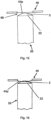
- An arcuate water droplet forms at the end of a capillary when the surface tension of the water exceeds capillarity.
- the capillarity of the wick relative to the surface tension of the water-based solution is selected so that the surface tension the water-based solution dominates, resulting in the formation of an arc-shaped water droplet at the end of the capillary.
- the second part of the ultrasonic generator is positioned so far away from the wick that the oscillating second part of the ultrasonic generator only dips into the water droplet without touching the wick itself. This prevents negative frequency interference with the ultrasonic generator, allowing aerosolization to occur as desired. As a result, unwanted droplet coalescence in the aerosol, which would then impede inhalation to the alveoli in the lungs, does not occur.
- the ultrasonic generator applies ultrasound to the liquid picked up by the outlet end of the wick, nebulizing the liquid and generating an aerosol from the liquid.
- the mouthpiece delivers the generated aerosol to an external part of the device, for example, when a user draws it in.
- the tank, wick, and mouthpiece together define a fluid pathway for transporting the liquid from the tank to the ultrasonic generator and for transporting the aerosol generated by the ultrasonic generator to the mouthpiece.
- the ultrasonic generator is positioned directly between the mouthpiece—an outlet port of the mouthpiece—and the wick.
- the fluid pathway also passes through the ultrasonic generator.
- the container has an outlet opening.
- the wick is arranged in the outlet opening such that the wick at least partially or completely fills the outlet opening.
- aerosol generation may also be referred to as nebulization, aerosolization, atomization, atomization and similar terms.
- the feature "arranged in contact” in the sense of the present invention can have the same meaning as “in direct contact”, “arranged in direct physical contact” or “arranged in surface contact”.
- the term "fillings" within the meaning of the present invention can have the same meaning as “completely filled,” “crammed,” “clamped,” or “occupies an entire cross-sectional area.”
- the cross-sectional plane or area is defined perpendicular to the longitudinal axis of the device and/or the tank and/or the guide.
- the operation of the aerosol generating device can be understood as follows:
- the liquid from the tank is drawn into the wick via the inlet end of the wick.
- the drawn liquid migrates through the wick to its outlet end as a result of the capillary action or wicking of the wick.
- the outlet end of the wick makes the liquid available to the ultrasonic generator, whereby according to an advantageous embodiment of the invention, there is no direct contact between the outlet end of the wick and the second part of the ultrasonic generator.
- the outlet end of the wick supplies the ultrasonic generator with the liquid to be nebulized through the capillary.
- an arc-shaped water droplet forms at the end of a capillary due to the surface tension of the water-based liquid.
- the surface tension arises due to the attractive forces between the water molecules at the interface between the water and the air.
- the water rises due to capillarity caused by adhesion and cohesion.
- the capillarity of the wick is selected in relation to the surface tension of the water-based solution in such a way that the surface tension of the water-based solution dominates, resulting in the formation of an arc-shaped water droplet at the end of the capillary, i.e. at the outlet end of the wick.
- the ultrasonic generator generates ultrasound, e.g., when operated or controlled by a user of the device, or activated, e.g., when supplied with electrical energy from a battery or power source.
- the generated ultrasound sprays the liquid provided by the outlet end of the wick, creating the aerosol, which is then mouthpiece to an exterior of the device.
- the atomization and subsequent removal of the liquid from the outlet end of the wick by the action of the ultrasonic generator provides suction or maintains a capillary or wicking action, drawing or transporting the liquid from a container into the inlet end of the wick and from there to the outlet end of the wick.
- the wick can be arranged at a distance from the surface of the ultrasonic generator and can be spatially sealed in such a way that, apart from the liquid transported by the wick, no other liquid can enter the ultrasonic generator.
- the liquid can reach the ultrasonic generator exclusively via the capillary element or the wick.
- the container is designed to be liquid-tight or fluid-tight except for its outlet opening, so that the liquid from the tank is transported to the ultrasonic generator only via the wick.
- This has the advantage of preventing unwanted leaks of liquid from the container and ensuring that the liquid stored in the tank of the container reaches the ultrasonic generator exclusively through the wick.
- the accumulation of liquid, which forms at the outlet end of the wick due to its surface tension, then ensures that liquid is absorbed by the second part of the ultrasonic generator when this second part is set into vibration and deforms towards the outlet end of the wick.
- the wick with its outlet end is in contact with the first part of the ultrasonic generator.
- the wick can be expedient for the wick to be prestressed by a compression spring along its longitudinal extent in the direction of the ultrasonic generator, such that the wick with its outlet end is pressed against the first part of the ultrasonic generator.
- the contact of the wick with the first part of the ultrasonic generator creates a sealing effect to the side, so that the accumulation of liquid at the outlet end of the wick is actually only located centrally opposite the second part of the ultrasonic generator. This ensures effective absorption of liquid in the passages of the second part of the ultrasonic generator when this second part deforms in the direction of the wick during vibration and immerses itself in the liquid as explained.
- the aforementioned spring preload for the wick can be achieved by arranging the compression spring in axial alignment with the wick and bearing against an end face of the wick where its inlet end is formed.
- the compression spring is arranged on the wick at its lower end face, which is opposite the ultrasonic generator.
- the compression spring can be supported on a base region of the container or on an associated lid, so that the spring force is exerted on the wick in the direction of the ultrasonic generator.
- the aforementioned spring preload for the wick has the advantage that the wick always forms a tight seal against the first part of the ultrasonic generator. On the one hand, this creates a sealing effect with respect to the outlet end of the wick, preventing any uncontrolled flow or escaping of the liquid that accumulates at the outlet end of the wick due to its surface tension. Furthermore, the spring preload ensures that the vibrations of the ultrasonic generator induced by its first part can be "accompanied" by the wick. This means that these vibrations of the first part can be transmitted to the wick without the contact between the wick and the first part of the ultrasonic generator being lost.
- the wick's outlet end is continuously pressed against the first part of the ultrasonic generator due to the spring preload of the compression spring.
- the vibrations are transmitted from the first part of the ultrasonic generator to the wick, its contact with the first part of the ultrasonic generator is maintained or not lost.
- the sealing effect described above which is achieved by the contact of the wick with the first part of the ultrasonic generator, remains unchanged even during vibration.
- the wick can be made of woven or non-woven fabric, such as cotton.
- any conduction or movement or transport of the liquid through the wick and/or in the wick and/or within the wick may be due to wicking or capillary action, e.g., if it is forced or effected or brought about by aerosolization of the liquid at the outlet end of the wick by the ultrasound generated by the ultrasonic generator.
- a material of the wick may be such that capillaries of the wick hold the liquid so that the liquid does not escape by itself, ie in the absence of the wick force generated by the operation (ie the ultrasound generation) of the ultrasonic generator. Only by the vibrations of the Ultrasonic generator, the liquid in the wick can escape from the capillaries of the wick.
- a position and/or orientation of the wick may be located or fixed with respect to the container, in particular with respect to the outlet opening of the container, for example, but not exclusively, by means of a press fit or interference fit.
- the above-mentioned fluid conduction path can be understood in the sense of the present invention as comprising at least two sections or parts or segments - a first section or segment, which can be referred to as a liquid transport section or segment, and a second section or segment, which can be referred to as an aerosol transport section or segment.
- the liquid transport section may be defined at least by the wick, for example, by the inlet end of the wick, the outlet end of the wick, and the intermediate or middle part of the wick (i.e., the part of the wick extending between the inlet end and the outlet end of the wick).
- the liquid is transported from the tank to the ultrasonic generator via the liquid transport section.
- the liquid transport section extends from the tank to the ultrasonic generator.
- the aerosol transport section can be defined by at least one space, chamber, or channel between the ultrasonic generator and an outlet opening (i.e., a discharge opening) of the mouthpiece.
- the aerosol generated at and by the ultrasonic generator is transported to the outlet opening of the mouthpiece via the aerosol transport section.
- the outlet opening may be an opening of the mouthpiece through which or via which the aerosol is ultimately discharged or dispensed from the mouthpiece and/or the aerosol generating device, for example to a user.
- the liquid transport section and the aerosol transport section are connected to each other or overlap continuously or partially, with these two sections together forming the fluid conduction path.
- the fluid conduction path extends through the ultrasonic generator.
- the ultrasonic generator may have a receiving surface (also referred to as the first surface or bottom surface or wick-side surface or bottom surface) and an exit surface (also referred to as the second surface or top surface or discharge opening-facing surface or top surface).
- the receiving surface and the exit surface of the ultrasonic generator can be inverted sides or surfaces, i.e. opposite sides or surfaces of the ultrasonic generator.
- the receiving surface of the ultrasonic generator faces the wick. According to an advantageous embodiment of the invention, this receiving surface is not in direct physical contact (surface contact) with the wick, i.e., with the outlet end of the wick.
- the receiving surface of the ultrasonic generator collects the liquid from an arc-shaped drop that forms on or at the outlet end of the wick.
- the exit surface of the ultrasonic generator faces the exit opening of the mouthpiece.
- the aerosol generated on and by the ultrasonic generator leaves the ultrasonic generator from the exit surface towards the exit opening of the mouthpiece.
- the ultrasonic generator can be configured to operate at a frequency in the range of 1.4 kHz to 3 MHz.
- the aerosol generating device in particular the ultrasonic generator, can be configured to generate aerosol from a water-based liquid (i.e., a liquid containing 80 wt% or more of water), wherein the aerosol has droplets with a size or an average size of 10 ⁇ m or less, in particular less than or equal to 5 ⁇ m, and/or equal to or greater than 1 ⁇ m, in particular greater than or equal to 2 ⁇ m, and/or without heating at least one of the fluids, the liquid and the aerosol (i.e., by maintaining a temperature of the liquid, a temperature of the aerosol can correspond to the temperature of the liquid).
- the aerosol can comprise a plurality of droplets with a size distribution with an average or mean value less than or equal to 10 ⁇ m, in particular less than or equal to 5 ⁇ m.
- the ultrasonic generator may comprise a first part, for example, a piezoelectric or piezoceramic part or element, and a second part, for example, a mesh or metal grid part, or a part with a plurality of passages formed therein, or a perforated part.
- the ultrasonic generator may comprise a first part comprising a piezoelectric element and a second part having a plurality of passages (for example, a mesh or a perforated plate) for allowing the fluid to pass through.
- the outlet end of the wick is not in contact with the second part of the ultrasonic generator. Consequently, the outlet end of the wick is also not in contact with the passages formed in the second part of the ultrasonic generator. This provides the advantage of the invention that the vibrations of this second part of the ultrasonic generator are not influenced or impaired by the wick during operation of the aerosol generating device.
- the second part of the ultrasonic generator can be set into vibration by its first part.
- the second part of the ultrasonic generator may be disc-shaped or circular.
- a diameter of the second part of the ultrasonic generator may be equal to or greater than a diameter of the outlet opening of the container and/or a diameter of the outlet end of the wick (which, as explained above, is not in contact with the second part).
- the second part of the ultrasonic generator can have a flat shape.
- the second part of the ultrasonic generator it is possible for the second part of the ultrasonic generator, as already mentioned above, to have a concave section.
- this concave section of the second part of the ultrasonic generator has a curved shape that extends away from the wick.
- the shape of the outlet end of the wick can also have a curved shape.
- a shape of the wick at the outlet end may correspond to the shape of the second part of the ultrasonic generator.
- the shape of the outlet end of the wick may also be planar.
- the second part of the ultrasonic generator may have a curved shape that protrudes toward or relative to the wick—for example, a concave or convex shape, such as a concave or convex dome shape.
- the shape of the outlet end of the wick and the shape of the second part of the ultrasonic generator can be be adapted, matched, corresponding, similar, or complementary. However, direct contact between the outlet end of the wick and at least the second part of the ultrasonic generator should be prevented.
- the second part of the ultrasonic generator can be surrounded by the first part.
- the first part of the ultrasonic generator may have an annular shape, for example an annular circular or disc shape, and the second part may be arranged at or in the center of the annular shape.
- the receiving surface and the exit surface of the ultrasonic generator can be surfaces of its second part.
- the receiving surface and the exit surface of the ultrasound generator may be in fluid communication with each other via the tissue or the passages or perforations of the second part.
- the fluid conduction path may extend through the second part of the ultrasound generator, i.e., through the fabric or the passages or perforations of the second part from the receiving surface to the exit surface of the ultrasound generator.
- the passages or mesh or perforations may form a part, segment, or portion of the fluid conduction path.
- a portion or segment of the fluid conduction path i.e. the portion disposed in or within or through the ultrasonic generator, may be surrounded by the first part of the ultrasonic generator.
- the first part of the ultrasonic generator may have an annular shape, for example an annular circular or disc shape, and the fluid conduction path may extend or pass through the center of the annular shape.
- the wick is arranged in the outlet opening of the container in such a way that the wick at least partially fills or completely fills the outlet opening.
- the wick can fill the outlet opening in such a way that the container is leak-proof or tight with regard to the liquid stored therein.
- the container can be leak-proof if the wick is positioned in and fills the outlet opening.
- the wick can fill the outlet opening of the container in such a way that a contact area between the wick and the opening is so leak-proof that the container is leak-proof and thus tight.
- the wick may comprise at least two sections or parts or segments, an inner or first section of the wick arranged to project out of the outlet opening and into the tank, and an opening or second section of the wick arranged in or within the outlet opening (i.e., not projecting from either side of the outlet opening or simply being confined or flush with the outer and inner surfaces of the container).
- the two sections or parts or segments of the wick may be formed as one piece.
- the wick may optionally comprise a third portion or part or segment - an outer portion of the wick disposed projecting from the outlet opening to an outer side of the container, i.e., disposed outside the tank and outside the outlet opening.
- the wick When inserting the wick into the outlet opening, the wick may be pressed into the outlet opening, i.e. by walls or surfaces (of the container) defining the outlet opening, whereby the wick thus assumes the cross-sectional shape and/or size (e.g. diameter) of the outlet opening.
- a standard cross-sectional shape of the wick e.g., the opening portion of the wick, and a cross-sectional shape of the outlet opening may be the same, e.g., Both can have a circular shape.
- a standard cross-sectional shape of the wick e.g., the opening portion of the wick, and a cross-sectional shape of the outlet opening may be different, and the wick is pressed into the outlet opening when inserted into the outlet opening, thus assuming the cross-sectional shape of the outlet opening.
- a standard cross-sectional shape of the wick can be understood as a cross-sectional shape of the wick before it is inserted into the outlet opening.
- a standard cross-sectional area of the wick e.g., the opening portion of the wick, may be larger than the cross-sectional area of the outlet opening.
- a preset cross-sectional area of the wick can be understood as a cross-sectional area of the wick before it is inserted into the outlet opening.
- the outlet opening may be completely filled with the wick or packed by the wick. In other words, the entire cross-sectional area of the outlet opening is occupied by the wick, so that the liquid in the tank flows through the outlet opening only over or through the wick.
- the wick is arranged through or in the outlet opening such that no gap, air gap, or spatial gap remains in the outlet opening, i.e., between an outer surface (e.g., an outer peripheral surface) of the wick and a surface of the container defining the outlet opening. Since there is no space, channel, or gap between the outer surface of the wick and the surface of the container that defines the outlet opening, any unintentional flow of liquid or vapor out of the container is reduced or eliminated.
- the wick may be inserted or pressed into the outlet opening, for example in such a way that the entire circumferential surface of the outlet opening is in direct contact (or in surface-to-surface contact) with an outer peripheral surface of the wick.
- the container for example the tank defined by the container, may be liquid-tight or hermetically sealed or fluid-tight, in particular for the flow of liquid from an interior of the container (i.e. the tank) to an exterior of the container (i.e. (i.e., outside an outer surface of the container).
- the container can be liquid-tight or hermetically sealed, except for its outlet opening, so that the liquid from the tank is transported to the ultrasonic generator only via the wick arranged in the outlet opening.
- the outlet opening of the container may be the only exit or drainage opening from the tank to an exterior of the container.
- the wick may comprise a solid body configured to exhibit capillary action or wicking.
- This reservoir may have a volume of 3 ml or less, particularly 2 ml or less.
- the container may have a guide that is tubular and extends from the outlet opening of the container into the tank.
- the guide and the container may be formed integrally.
- an inner diameter of the guide may be equal to a diameter of the outlet opening of the container.
- the guide may have a receiving space.
- the wick is accommodated in the receiving space.
- the guide may only occupy a portion of the tank.
- the guide may occupy between 10 and 90 percent of the total tank volume, or between 20 and 80 percent of the total tank volume, or between 30 and 70 percent of the total tank volume, or between 10 and 30 percent of the total tank volume.
- the receiving space may be continuously connected to the outlet opening and/or be in fluid communication with the outlet opening.
- the receiving space may be formed sequentially with the outlet opening.
- the outlet opening can preferably be in fluid communication with the tank exclusively via the receiving space.
- the receiving space can be concentric and/or coaxial with the outlet opening.
- a cross-sectional area of the receiving space can be filled by the wick.
- the cross-sectional area of the receiving space can be equal to or smaller than a cross-sectional area of the outlet opening. Additionally or alternatively, the cross-sectional area of the receiving space can be constant along a longitudinal axis thereof.
- An entire or complete internal volume of the guide may be filled by the wick or completely filled or packed.
- the receiving space can be completely or completely packed (in cross-section and longitudinal direction) or completely packed by the wick.
- the standard cross-sectional shape of the wick e.g., the inner portion of the wick, and a cross-sectional shape of the receiving space may be identical, e.g., both may be circular.
- the standard cross-sectional shape of the wick e.g., the inner portion of the wick, and a cross-sectional shape of the receiving space may be different, and the wick, when inserted into the receiving space, may be forced through a peripheral wall (defining the receiving space) of the guide, thus assuming the cross-sectional shape of the receiving space.
- the standard cross-sectional area of the wick e.g. the inner section of the wick, may be larger than the cross-sectional area of the receiving space.
- the container for example the one formed by the Container defined tank, liquid-tight or hermetically sealed or fluid-tight.
- the container for example the tank defined by the container, may be liquid-tight or hermetically sealed or fluid-tight, in particular for the flow of liquid from the interior of the container (i.e. from the tank) to the exterior of the container (i.e. outside an exterior surface of the container).
- the outlet opening and the associated receiving space may define or form the only exit from the tank to the outside of the container.
- the outlet opening and/or the receiving space can be completely filled with the wick, or can be stuffed or packed by the wick. In other words, the entire cross-sectional area of the outlet opening and/or the receiving space is occupied by the wick, so that the liquid in the tank flows through the outlet opening and/or the receiving space only via the wick, or through an interior of the wick, or through a body of the wick, or through capillary channels or interstices of the wick.
- the wick can be arranged through or in the outlet opening and/or the receiving space such that no gap, air gap, or air channel remains in the outlet opening and/or the receiving space between an outer surface, e.g., an outer peripheral surface, of the wick and the surface of the container defining the outlet opening and/or the peripheral wall of the guide defining the receiving space. Since there is no space or channel or gap between the outer surface of the wick and the surface of the container defining the outlet opening and/or the peripheral wall of the guide defining the receiving space, any unintended flow of liquid or vapor from the container is reduced or eliminated.
- the container can be liquid-tight except for the outlet opening and the associated receiving space, so that the liquid from the tank is transported to the ultrasonic generator only or exclusively via the wick arranged through the receiving space and the outlet opening.
- the guide may have an inlet end with an inlet or inlet hole.
- the inlet end of the wick may be in fluid communication with the tank via the inlet of the guide.
- the guide may have a circumferential wall extending between the inlet end of the guide and an outlet end of the guide.
- the outlet end of the guide may have an outlet or outlet hole communicating with the outlet opening.
- the outlet of the guide may have the same diameter and/or cross-sectional area as the outlet opening of the container.
- the outlet end of the guide can be connected or coupled to the inner surface of the container.
- the coupling can be fluid-tight or liquid-tight.
- the surrounding wall of the guide can be so liquid-tight that the liquid in the receiving space only enters the wick via the inlet of the guide.
- a gap may be defined between the guide, i.e., the inlet end of the guide, and the inner surface of the container.
- the liquid stored in the tank is absorbed into the wick through the gap.
- the wick may be arranged such that it projects from the guide, i.e. from the inlet end of the guide, into the tank.
- the wick may be arranged such that it projects from the guide, i.e. from the inlet end of the guide, into the gap.
- the guide can hermetically separate the receiving space of the container from the ultrasonic generator, except through the receiving space.
- the wick may protrude from or from the outlet opening to the ultrasonic generator. This means that the outlet opening may be spaced apart from the ultrasonic generator.
- the wick may protrude from the outlet opening and extend beyond an outer surface of the container. In other words, the protruding portion or outer portion or part of the capillary element or wick may be located entirely outside the container.
- a length of the guide extending from the outlet opening of the container into the tank may be equal to or greater than 50 percent of a length of the tank, or equal to or greater than 70 percent of a length of the tank, may be equal to or greater than 80 percent of a length of the tank, or may be equal to or greater than 90 percent of a length of the tank.
- a length of the wick extending from the outlet opening of the container into the tank may be equal to or greater than 50 percent of a length of the tank, or may be equal to or greater than 70 percent of a length of the tank, may be equal to or greater than 80 percent of a length of the tank, or may be equal to or greater than 90 percent of a length of the tank.
- a (total) length of the wick may be greater than a length of the guide and/or may be greater than a combined length of the guide and the outlet opening.
- the length of the guide may be measured from an edge of the outlet opening facing the receiving space.
- the length of the tank may be measured from an edge of the outlet opening facing the tank to a bottom surface of the tank, i.e., an area of the bottom wall of the tank that defines the tank.
- the guide may have a cylindrical shape, e.g. the shape of a right circular cylinder, and may have different cross-sectional shapes, such as circular, triangular, polygonal.
- the wick may have a cylindrical shape, e.g., the shape of a right circular cylinder, and may have various cross-sectional shapes, such as circular, triangular, polygonal.
- the container may have a cylindrical shape, e.g. the shape of a right circular cylinder or a cuboid, and may have different cross-sectional shapes, such as circular, triangular, polygonal.
- the container may also have different parts or sections with different shapes - such as a first part or segment with a cylindrical shape and a second part or segment with a frustoconical or cuboidal or frustoconical or frustoconical shape.
- the guide and/or wick may extend along a longitudinal axis of the container and/or the aerosol generating device.
- the guide and/or wick may be coaxial and/or concentric with the container and/or with the aerosol generating device.
- the guide and/or the wick may be arranged along the longitudinal axis of the container and/or the aerosol generating device.
- the longitudinal axis may be a central longitudinal axis of the container and/or the aerosol generating device.
- the container may comprise a body.
- the body may be formed as a single piece, e.g., molded or 3D printed in one piece. Alternatively, the body may be formed in multiple parts.
- the parts may be connectable to one another with a fluid-tight joint to form the body of the container.
- the parts may be molded or 3D printed.
- the container may have an inlet opening for filling or refilling the liquid into the tank.
- the container may have a closure for closing the inlet opening.
- the closure may be a seal or cap formed of an elastomeric material, such as rubber, that can be detached from the opening to refill the tank.
- a refilling device e.g., a syringe needle
- the closure can be a valve, e.g. a one-way valve or a filling valve (filling valve or refilling valve).
- the container may have a seal or sealing element at the outlet opening and in contact with an outer surface of the wick.
- the sealing element may be disposed inside the outlet opening or outside the outlet opening.
- the sealing element may protrude into the outlet opening.
- An example of the sealing element may be a gasket, e.g., a gasket formed from an elastic material such as a rubber gasket.
- the device may further comprise a holding element arranged between the mouthpiece and the container and/or arranged on or on the container to support or mount or fix the ultrasonic generator.
- the ultrasonic generator can be mounted on the holding element or accommodated in it.
- the holding element may, for example, be formed from an elastic or elastomeric material, such as silicone or rubber, and may be a cushion to hold and support the ultrasonic generator.
- the retaining element may be configured to dampen the vibrations and/or noise generated by the ultrasonic generator transmitted to the container and/or the mouthpiece and/or an external surface of the device.
- the container may include a container connector, and the holding element may include a holding element connector.
- the container connector and the holding element connector may correspond to each other and may engage with each other to fix or couple the container and the holding element to the ultrasonic generator mounted thereon.
- the coupling may be releasable or reversible.
- the mouthpiece, the ultrasonic generator and the wick can be aligned axially or linearly, i.e. in a straight line.
- the ultrasonic generator can be stacked in a straight line on the outlet opening of the container and the wick; and the mouthpiece can be stacked in a straight line on the ultrasonic generator.
- the longitudinal axis of the ultrasonic generator may mean a longitudinal axis of the first part and the second part of the ultrasonic generator.
- the first part and the second part may have the same longitudinal axis.
- the longitudinal axis of the guide may mean the longitudinal axis of the receiving space of the guide.
- the longitudinal axis of the container may mean the longitudinal axis of the receiving space of the container.
- the wick can be placed in the tank without completely filling the tank.
- a section or portion of the sub-volume or segment of the tank may be free of wick or absorbent material and may be a free space or volume to receive and hold the liquid in a free form or state (i.e., without being adsorbed or held by the wick or any absorbent material). This allows at least a portion of the tank to be used exclusively to hold the liquid to be nebulized, which can then be transported via the wick to the ultrasonic generator.
- the wick may be arranged within the tank and fill a cross-section of the tank or the entire tank.
- the guide may optionally be omitted.
- the wick can be arranged in the tank such that it fills a cross-section of the tank, i.e., is in contact with the inner surface of the tank.
- the outlet opening can have a diameter and/or a shape and/or a cross-sectional area corresponding to that of the receiving space.
- the wick can be arranged such that it fills a cross-sectional area of a first portion of the tank.
- a second portion of the tank can be between the wick and a bottom region of the tank. The second portion is free of wick material and/or capillary material.
- the wick can fill the entire tank.
- the container may comprise a guide segment that defines the receiving space or may be formed entirely by this guide segment.
- the wick can be arranged in the outlet opening, wherein the guide segment is arranged such that the wick fills or completely fills the outlet opening and/or the receiving space of the guide segment.
- the guide segment can absorb the liquid adsorbed in the arranged wick.
- the guide segment can form the entire tank.
- the container may have a reservoir segment in addition to the guide segment.
- the reservoir segment does not contain the wick or is free of the wick, i.e., it is not filled by the wick and can therefore absorb the liquid therein.
- the reservoir segment of the tank may be free of the wick or any absorbent material and may be a free space or volume to receive and hold the liquid in a free form or state (i.e., without being adsorbed or held by the wick or any absorbent material). Consequently, the reservoir segment may be used exclusively to receive the liquid to be aerosolized. which can then be transported to the ultrasound generator via the wick arranged in the guide segment, as explained.
- the tank, the wick and the mouthpiece define a fluid conduction path for transporting the liquid from the tank to the ultrasonic generator and for transporting the aerosol generated by the ultrasonic generator to the mouthpiece, preferably that the fluid conduction path runs through the ultrasonic generator and the container, further preferably that the wick is arranged in the outlet opening of the container and fills the outlet opening.
- the liquid used in conjunction with the aerosol generating device and method according to the invention may be a water-based nicotine liquid.
- this liquid it is important for this liquid to have a surface tension sufficient to form a sufficient pool of liquid at the outlet end of the wick for transfer to the ultrasonic generator.
- the liquid may contain at least one additional ingredient, e.g. tobacco extract, nicotine extract, flavoring such as mint extract, clove extract, etc.
- additional ingredient e.g. tobacco extract, nicotine extract, flavoring such as mint extract, clove extract, etc.
- An amount of ethanol and/or at least one additional component in the liquid may be equal to or greater than 10% by weight and equal to or less than 20% by weight.
- the liquid must not contain one or more or all of the following substances: glycerin, propylene glycol, and oil.
- the liquid must not contain at least one or all of glycerin, propylene glycol, and oil, preferably with the exception of essential oils and/or flavor additives.
- the temperature of the liquid and the temperature of the aerosol can be the same.
- no heating effect is performed by the ultrasonic generator.
- no heating effect is required to convert the liquid into the aerosol.
- No heating action shall be carried out at the time and/or place of aerosolization, i.e. the generation of aerosol from the liquid.
- the ultrasonic generator can oscillate at a frequency of less than or equal to 3.5 MHz (megahertz) or less than or equal to 3 MHz, in particular at a frequency in the range from 1.4 kHz to 3 MHz.
- a diameter of the droplets of the aerosol generated by the ultrasonic generator can be less than or equal to 10 ⁇ m, in particular less than or equal to 5 ⁇ m and/or equal to or greater than 1 ⁇ m, in particular greater than or equal to 2 ⁇ m.
- Droplet size can be measured by light diffraction, e.g., laser light diffraction, or by light scattering, e.g., laser light scattering.
- suitable droplet size measurement systems include the Spraytec TM from Malvern Panalytical Ltd or the LS 13 320 XR particle analyzer from Beckmann Coulter GmbH.
- liquid-tight in the context of the present invention means impermeable to any fluid, including a gas, vapor, or liquid, e.g., impermeable to the liquid stored in the tank or to the vapor generated from the liquid stored in the tank.
- liquid-tight in the context of the present invention means impermeable to any liquid, e.g. impermeable to the liquid stored in the tank.
- 'upstream', 'downstream', 'top', 'upper', 'bottom', 'bottom' and similar expressions may be understood in relation to a direction or path of the liquid (to be aerosolized) from the tank to the ultrasonic generator and of the aerosol from the ultrasonic generator to the mouthpiece.
- the unintentional accumulation of droplets on the surface of the ultrasonic generator facing the outlet opening of the container i.e., the inner surface or the underside of the ultrasonic generator, is reduced or prevented. Consequently, any migration of the liquid through the ultrasonic generator, e.g., through the opening or passages or meshes of the ultrasonic generator to the top of the ultrasonic generator, is reduced or stopped, thus reducing or stopping droplet formation on the top of the ultrasonic generator.
- the above-mentioned effect not only increases the speed and efficiency of restarting and nebulization, but also allows the use of liquid with high water content.
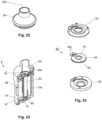
- FIG. 1 and 2 show perspective views of an exemplary embodiment of an aerosol generating device 1 (hereinafter also referred to as device) in an assembled or mounted state.
- Fig. 3 shows the aerosol generating device 1 of Fig. 1 in a disassembled or dismantled state.
- the aerosol generating device according to the invention Fig. 1 or Fig. 3 may be a personal vaporizer, an inhaler, an electronic cigarette, or e-cigarette. It should be noted that, although in the present description, the device is illustrated as having a structure that can be assembled and disassembled, the device according to the invention is not limited thereto. This means that the device 1 according to the invention may have a unitary structure, ie, it cannot be assembled and disassembled, or it may have a structure that can be assembled and disassembled, but differs from the structure according to the Fig. 1 - 3 differs.
- the aerosol generating device 1 can extend along a longitudinal axis 1x (cf. Fig. 2 , Fig. 11 ).
- the aerosol generating device 1 may have a linear shape extending along the longitudinal axis 1x, such as a rod shape or bar shape.
- the aerosol generating device 1 may comprise a main part (or handpiece) 8 and a cartridge part 9 (hereinafter always referred to as "cartridge").
- the cartridge 9 is Fig. 3 shown when it has been dismantled from the main part 8, ie removed therefrom.
- the aerosol generating device e.g. its main part 8, can accommodate a power supply (not shown), such as a battery unit for powering an ultrasonic generator (not included in the Fig. 1-3 shown and explained later) and/or other electronic components.
- a power supply such as a battery unit for powering an ultrasonic generator (not included in the Fig. 1-3 shown and explained later) and/or other electronic components.
- the aerosol generating device 1 may also include a control device (not shown) for controlling operation of the power supply and the ultrasonic generator and/or other components of the device 1.
- the aerosol generating device 1 may further include a charging port 82 for charging the power supply of the device 1 by providing an external power supply or one or more indicators such as LED indicators 84, 88. These indicators serve to indicate the operating state of the device 1 and/or a charging state of the device 1, e.g., a fully charged state, a low battery state, a state in which the ultrasonic generator is powered to generate ultrasound, or a standby state.
- a charging port 82 for charging the power supply of the device 1 by providing an external power supply or one or more indicators such as LED indicators 84, 88. These indicators serve to indicate the operating state of the device 1 and/or a charging state of the device 1, e.g., a fully charged state, a low battery state, a state in which the ultrasonic generator is powered to generate ultrasound, or a standby state.
- the aerosol generating device 1 can have a user interface 88 (cf. Fig. 1 ), e.g., a button, such as an ON/OFF button, that a user can actuate, e.g., press, to control the function or operation of the device 1, such as inputting a user command to implement the power supply of the ultrasonic generator to generate or produce ultrasound for aerosol.
- a user interface 88 e.g., a button, such as an ON/OFF button, that a user can actuate, e.g., press, to control the function or operation of the device 1, such as inputting a user command to implement the power supply of the ultrasonic generator to generate or produce ultrasound for aerosol.
- the device 1 may have a surface feature 89, such as a logo or branding or a non-slip surface modification.
- the aerosol generating device 1, e.g., the cartridge 9, may comprise a reservoir or a container (not included in the Fig. 1 - 3 shown, but explained later) for receiving or containing a liquid to be nebulized to produce aerosol, and a mouthpiece 50 for delivering the aerosol thus produced to an outside of the device 1.
- the main part 8 and the cartridge 9 may be formed as one body or have a structure which can be connected to one another by means of engaging parts 8x, 9x which are provided on the main part 8 and the cartridge 9 (cf. Fig. 3 ), can be assembled and disassembled.
- the main part 8 may contain a main engagement part 8x and the cartridge 9 may contain a cartridge engagement part 9x (cf. Fig. 3 ).
- the main engagement part 8x can be reversibly engaged with and released from the cartridge engagement part 9x in order to connect or separate the main part 8 and the cartridge 9. In this way, the device 1 with its components, main part 8 and cartridge 9, can be assembled or disassembled again if necessary.
- Electrical contacts or connections 9y to electrically or signal-technically connect the power supply (contained in the main part 8) and the ultrasonic generator 40 (contained in the cartridge 9) to each other.
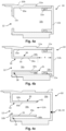
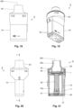
- the device 1, ie the cartridge 9, comprises a container 10 as shown in the Fig. 4a, 4b and 4c shown, with an outlet opening 12, a wick 20 fitted into the outlet opening 12, as shown in the Fig. 5a and 5b shown, and an ultrasonic generator 40 (also referred to as ultrasonic transducer or probe or head or actuator) arranged opposite the wick 20, as shown in the Fig. 9a and Fig. 9b is shown.
- an ultrasonic generator 40 also referred to as ultrasonic transducer or probe or head or actuator
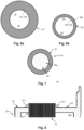
- Fig. 7 shows an exemplary embodiment of the ultrasonic generator 40, which is part of the aerosol generating device 1 according to the invention and is mounted in the cartridge 9.
- the ultrasonic generator 40 can have a first part 42 comprising a piezoelectric element; and a second part 44 having a plurality of passages 44p or a mesh 44p, e.g., a metallic mesh.
- the passages 44p or the mesh 44p make the second part 44 of the ultrasonic generator 40 permeable to liquid and in particular to the aerosol generated by the ultrasonic generator 40. Further details on the ultrasonic generator 40 and its interaction with the wick 20 are explained separately below.
- the first part 42 of the ultrasonic generator 40 may have an annular shape, wherein the second part 44 of the ultrasonic generator 40 may be arranged in a center of the annularly shaped first part 42.
- the second part 44 of the ultrasonic generator 40 has two opposite or inverted sides or surfaces - a receiving surface and an exit surface - which are in fluid communication with each other via the mesh 44p or the passages 44p.
- the receiving surface of the second part 44 of the ultrasonic generator 40 can be understood as the surface of the second part 44 facing the outlet opening 12 and the outlet end 22 of the wick 20.
- the exit surface of the second part 44 can be understood as the surface of the second part 44 facing the mouthpiece 50 or facing an exit opening 50h of the mouthpiece 50.
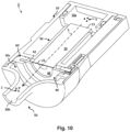
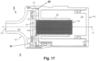
- Fig. 10 , 11 and 12 show an exemplary embodiment of the device 1, in which the container 10, the wick 20, the ultrasonic generator 40 and the mouthpiece 50 are shown in their arrangement relative to one another.
- the container 10 may include a guide 30 as shown in Fig. 4b and 4c shown, or the guide 30 can be moved as shown in Fig. 4a shown, not included.
- the Fig. 10 and 11 show an exemplary embodiment of the device 1 with the guide 30. However, the Fig. 10 and 11 The arrangement shown can be applied mutatis mutandis to the device 1 without the guide 30.
- Figure 12 shows an exemplary embodiment of the device 1 without the guide 30.
- the container 10 comprises a liquid reservoir in the form of an accommodation space 10s (hereinafter always referred to as "tank").
- This tank 10s serves to store or hold a liquid 3 (in Fig. 10 symbolized by three dots) that is to be sprayed.
- the container 10 may be formed from a polymeric material, such as plastic.
- the container 10 may have at least a part or segment that is transparent and allows a view of an interior of the container 10, i.e., the tank 10s, whereby a user can see the level of the liquid present in the tank 10s.
- the container 10 may include a body 11.
- the body 11 may include the outlet opening 12.
- the body 11 may be formed in one part, ie it may be formed in one piece, as in Fig. 4c shown; or may be formed by a plurality of parts 11a, 11b, as shown in the Fig. 4a and 4b shown, such as a first body segment or part 11a, e.g., a main container body 11a, and a second body segment or part 11b, e.g., a container lid 11b.
- the parts 11a, 11b can be connected with a liquid-tight connection 11x therebetween to form or completely assemble the body 11 of the container 10.
- the parts 11a, 11b can be reversibly connectable with the liquid-tight connection 11x, i.e., they can be coupled and decoupled from each other.
- the liquid-tight connection 11x can be a screw and thread connection or a press-fit connection, etc.
- the container 10 - regardless of whether it is formed in one part, as in Fig. 4c shown, or assembled by several interconnectable parts is, as in Fig. 4a and 4b shown - may define the tank 10s fluid-tight or liquid-tight or hermetically sealed with respect to an exterior of the container 10, except for the outlet opening 12 or adjacent areas thereof.
- the tank 10s of the container 10 is in fluid communication with an outside of the container 10 to allow the liquid to flow from the tank 10s to the outside of the container 10 only via the outlet opening 12.
- the container 10 or the body 11 of the container 10 may have the guide 30 extending from the outlet opening 12 into the tank 10s.
- the guide 30 may have a hollow tubular shape and define a receiving space 30s.
- the guide 30 may be attached to or contact a portion of the inner surface of the container 10 that surrounds or circumscribes the outlet opening 12.
- the outlet opening 12 may be located on an inner surface of the container 10 within the guide 30 or within a peripheral wall 35 of the guide 30.
- a contact interface or portion 38 between the guide 30 and the inner surface 10a of the container 10 may be liquid-tight or hermetically sealed.
- the guide 30 may be integrally formed with the portion of the inner surface of the container 10 that surrounds or circumscribes the outlet opening 12.
- the guide 30 may comprise a hollow, tubular body having an outlet end 32 connected to the inner surface 10a of the container 10, surrounding or surrounding the outlet.
- the outlet end 32 of the guide 30 may have an outlet 32h in fluid communication with the outlet opening 12.
- the hollow, tubular body of the guide 30 may have an inlet end 31 (cf. Fig. 4b, Fig. 4c ) which is arranged inside the tank 10s and from the Inner surface 10a of the container 10 (or in the embodiment of Fig. 4a and Fig. 4b : is spaced from the container lid 11b) by a gap 4.
- an inlet end 31 cf. Fig. 4b, Fig. 4c
- the hollow, tubular body of the guide 30 may have an inlet end 31 (cf. Fig. 4b, Fig. 4c ) which is arranged inside the tank 10s and from the Inner surface 10a of the container 10 (or in the embodiment of Fig. 4a and Fig. 4b : is spaced from the container lid 11b) by a gap 4.
- the inlet end 31 of the guide 30 can have an inlet 31h (cf. Fig. 4c ) which is in fluid communication with the tank 10s.
- the peripheral wall 35 of the guide 30 may extend longitudinally between the inlet end 31 and the outlet end 32 of the guide 30.
- the tank 10s of the container 10 is in fluid communication with an outside of the container 10 to allow the liquid to flow from the tank 10s to the outside of the container 10 only via the guide 30 and the outlet opening 12, for example only via the inlet 31h, the tank 30s, the outlet 32h and the outlet opening 12 arranged one behind the other.
- the guide 30 may be arranged within the tank 10s in a cantilevered arrangement and may be connected to the inner surface 10a of the container 10 only at one end of the guide 30, i.e., the outlet end 32 of the guide 30.
- the peripheral wall 35 and the inlet 31 of the guide 30 may be spaced from the inner surface 10a of the container 10.
- the container 10 may further comprise an inlet opening 18 and a lid 19 (cf. Fig. 4c ) that covers or seals the inlet opening 18.
- the inlet opening 18 and/or the lid 19 must only allow liquid to flow into the tank 10s from an outside of the container, i.e., the liquid from the tank 10s must not flow out of the tank 10s via the inlet opening 18 and/or the lid 19.
- the inlet opening 18 and/or the lid 19 can be used to fill or refill the liquid into the tank 10s.
- Fig. 5a shows the wick 20 which is inserted into and through the outlet opening 12 of the Fig. 4a shown container 10 is inserted
- Fig. 9a shows the ultrasonic generator 40, which is adjacent to the Fig. 5a shown wick 20 is arranged.
- Fig. 5b shows the wick 20 inserted into and through the outlet opening 12 and the guide 30 of the container 10 inserted into Fig. 4b and Fig. 9b is shown. Furthermore, Fig. 9b the ultrasonic generator 40, which is adjacent to the Figure 5b shown wick 20 is arranged.
- the wick 20 may have a rigid tubular shape and may be configured to transport liquid by capillary action or wicking.
- the wick 20 transports the liquid from the tank 10s to the ultrasonic generator 40 via the outlet opening 12 (if the container 10 does not contain the guide 30) or via the outlet opening 12 and the guide 30 (if the container 10 contains the guide 30).
- the wick 20 has an inlet end 21 for receiving the liquid 3 from the tank 10s into the wick 20.
- the inlet end 21 is arranged within the container 10, ie, in the tank 10s, for receiving the liquid 3.
- the wick 20 has, on its opposite end face, which is located opposite the ultrasonic generator 40, an outlet end 22 that is not arranged in contact with the ultrasonic generator 40. In any case, the outlet end 22 supplies the ultrasonic generator 40 with the liquid 3.
- the ultrasonic generator 40 may be shaped to extend into the outlet opening 12 without directly contacting the outlet end 22.
- a second portion (described later) of the ultrasonic generator 40 may be shaped to extend into the outlet opening 12.
- the ultrasonic generator 40 applies ultrasound to the liquid received from the outlet end 22 of the wick, thereby spraying the liquid 3 and generating the aerosol 2 from the liquid 3 (as shown in Fig. 10 shown).
- the mouthpiece 50 delivers the generated aerosol 2 to an exterior of the device 1, for example when it is pulled or sucked in by a user.
- the ultrasonic generator 40 is arranged, e.g., directly, between the mouthpiece 50 and the wick 20.
- the fluid conduction path 5 also runs through the ultrasonic generator 40.
- the wick 20 is arranged in the outlet opening 12 such that the wick 20 fills the outlet opening 12, ie completely fills it.
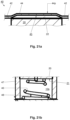
- FIG. 6a This is a cross section along line II of Fig. 5a . As can be seen from the Fig. 6a As can be seen, an outer peripheral surface 20c of the wick 20 can directly contact an entire peripheral surface defining the outlet opening 12.
- the outlet opening 12 can be completely filled or stuffed by the wick 20.
- the entire cross-sectional area of the outlet opening 12 is occupied by the wick 20 such that the liquid in the tank 10s flows through the outlet opening 12 only via the wick 20.
- the wick 20 is arranged in the outlet opening 12 and the guide 30 in such a way that the wick 20 covers the outlet opening 12 and/or the receiving space 30 of the guide 30 fills or completely fills.
- Fig. 6b which is a cross-section along the line II-II of the Fig. 5b the outer peripheral surface 20c of the wick 20 can directly contact an inner surface 30a of the peripheral wall 35 of the guide 30 at least over a lateral cross-section perpendicular to the longitudinal axis of the guide 30.
- the wick 20 occupies an entire volume or space of the receiving space 30s of the guide 30.
- the outlet opening 12 and/or the receiving space 30 of the guide 30 can be completely filled or stuffed by the wick 20.
- the wick 20 can be received in the outlet opening 12 and/or the receiving space 30s of the guide 30 by fitting it into the outlet opening 12 and/or the receiving space 30s of the guide 30.
- a sealing element 12s e.g., a rubber seal, as used, for example, in Figure 8 shown, be arranged at the outlet opening 12.
- the seal 12s may contact the outer peripheral surface 20c of the wick 20.
- the outlet end 22 of the wick 10 is not in direct contact with the second part 44 of the ultrasonic generator 40, as will be explained separately below.
- the device 1 can further comprise a holding element 60 (cf. Fig. 10 ) arranged between the mouthpiece 50 and the container 10.
- the ultrasonic generator 40 can be mounted on the support member 60 or received in the support member 60 to support, mount, or fix the ultrasonic generator 40 between the mouthpiece 50 and the container 10.
- the container may have a container connecting element 15 (as shown for example in Fig. 8 shown), and the holding element 60 may have a holding element connecting element (not shown).
- the container connecting element 15 and the holding element connecting element may correspond to each other and may engage with each other to fix or couple the container 10 and the holding element 60 with the ultrasonic generator 40 mounted thereon. This is shown in the Fig.9a and 9b
- the coupling can be detachable or reversible.
- Fig. 12 shows a further exemplary embodiment of the device 1, in which the wick 20 can be arranged directly in the tank 10s, ie in contact with the inner surface 10a of the tank 10s, and occupies the tank 10s - wholly or partially.
- the container 10 may have a guide segment 10g that defines the receiving space 30s.
- the wick 20 is arranged in the outlet opening 12 and the guide segment 10g such that the wick 20 fills or completely fills the outlet opening 12 and/or the receiving space 30s of the guide segment 10g.
- the guide segment 10g can absorb the liquid 3 adsorbed in the wick 20 arranged therein.
- the guide segment 10g can form the entire tank 10s.
- the container 10 may comprise a reservoir segment 10f in addition to the guide segment 10g.
- the reservoir segment 10f does not encompass the wick 20, i.e., it is not filled by the wick 20 and can hold the liquid 3 therein (cf. Fig. 12 ).
- the wick 20 can have a full length FL between 15 mm and 25 mm, for example 19 mm.
- a total length PL of the guide 30 and the outlet opening 12 can be between 12 mm and 18 mm, for example 16 mm.
- the wick 20 may comprise at least two sections or parts or segments - an inner section 24, i.e. a first section of the wick 20, which is arranged outside the outlet opening 12 and in the tank 10s, and an opening section 25, i.e. a second section, of the wick 20, which is arranged entirely in or inside the outlet opening 12, i.e. which does not protrude from the outlet opening 12 on any side.
- the wick 20 may optionally comprise a third section or part or segment - an outer section or an outer section 26 of the wick, which is arranged protruding from the outlet opening 12 to the outside of the container 10, i.e. arranged outside the tank 10s and outside the outlet opening 12.
- the wick 20 may protrude on both sides, i.e. the inlet end 21 of the wick 20 may protrude from the guide 30 into the tank 10s and the outlet end 22 of the wick 20 may protrude from the outlet opening 12 to an outside of the container 10 or the tank 10s.
- Fig. 15 The arrangement between the ultrasonic generator 40 and the outlet end 22 of the wick 20 is shown in the resting state of the ultrasonic generator 40. Due to the surface tension of the liquid 3, an accumulation of the liquid 3 forms as an arc-shaped drop on or at the outlet end 22 of the wick 20.
- the surface tension of the liquid 3 is selected to be sufficiently high or has a sufficiently high value that an accumulation of the liquid 3 forms as an arc-shaped drop on or at the outlet end 22 of the wick 20 (cf. Fig. 15 , Fig. 26 , Fig. 27 ).
- the invention ensures that any germ-inhibiting substances or other liquid components contained in the liquid 3 which prevent contamination of the aerosol generating device 1 do not reduce the surface tension of the liquid 3 to such an extent that there is no longer any accumulation of liquid 3 at the outlet end 22 of the wick 20.
- the outlet end 22 of the wick 20 has a distance of 90 (cf. Fig. 15 ) to the passages 44p formed in the second part 44 of the ultrasonic generator 40.
- This distance 90 can be achieved by stops, edges, spacer discs or spacer rings (not shown), or any other structural means for creating a distance.
- the Fig. 16 shows a partial view of the arrangement between the ultrasonic generator 40 and the outlet end 22 of the wick 20 while the second part 44 (with its passages 44p) is vibrated.
- the second part 44 of the ultrasonic generator 40 can be set into vibration by its first part 42.
- the passages 44p formed in the second part 44 touch or dip into the liquid 3 at the outlet end 22 of the wick 20, so that these passages 44p fill with the liquid 3. Due to the high frequency of the oscillations, the liquid 3 then emerges as an aerosol from the second part 44 of the ultrasonic generator 40 on its opposite side.
- the outlet end 22 of the wick 30 is exposed to an outer side of the outlet opening 12 and can either be flush with the outer surface 10b of the container 10 or protrude outwardly from the outer surface 10b of the container 10 or be arranged within the outlet opening 12.
- the outlet end 22 of the wick 20 is not in direct contact with the second part 44 of the ultrasonic generator 40.
- the outlet end 22 of the wick 20 is not in contact with the passages 44p or the mesh 44p formed in or by the second part 44 of the ultrasonic generator 40.
- the outlet end 22 of the wick 20 is not in direct contact with the second part 44 of the ultrasonic generator 40 at its receiving surface.
- the liquid 3 is supplied through the outlet end 22 of the wick and received by the receiving surface of the second part 44 of the ultrasonic generator 40.
- the first part 42 of the ultrasonic generator 40 oscillates by piezoelectric action and then implements or transmits the oscillations to the second part 44 of the ultrasonic generator 40, for example by it is in direct contact with the second part 44.
- the second part 44 of the ultrasonic generator 40 also oscillates.
- the liquid is taken up by the outlet end 22 of the wick 20 and suitably nebulized, and then at the opposite exit surface of the second part 44 as an aerosol 2 (cf. Fig. 10 ) into the aerosol chamber 50s and towards the outlet opening 50h of the mouthpiece 50.
- the generated aerosol 2 (cf. Fig. 10 ) then leaves the second part 44 of the ultrasonic generator 40 at or from the exit surface of the second part 44 of the ultrasonic generator 40, ie on its side opposite the wick 20.
- the surface tension of the liquid 3 is selected or set sufficiently high so that a collection of liquid 3 always forms at the outlet end 22 of the wick 20, opposite the ultrasonic generator 40 and its second part 44.
- this collection of liquid 3 serves, as explained, for transfer to the ultrasonic generator 40 and its second part 44, in particular when the latter is set into vibration during its actuation.
- the generated aerosol 2 is discharged from the exit surface of the second part 44 of the ultrasonic generator 40 into an aerosol chamber 50s (cf. Fig. 10 ) which is defined between the outlet opening 50h of the mouthpiece 50 and the ultrasonic generator 40, and then via the outlet opening 50h of the mouthpiece 50 to the outside of the device 1 or to the outside area A (cf. Fig. 17 ) of cartridge 9.
- Fig. 17 shows a further embodiment of the aerosol generating device 1 according to the invention, in which at least one flavored element 92 with a predetermined flavor is provided.
- a bypass 91 is formed within the mouthpiece 50, through which a fluid connection is formed between the aerosol chamber 50s of the mouthpiece 50 and an outer region A of the aerosol generating device 1 or the associated cartridge 9. Accordingly, during operation of the aerosol generating device 1, when a user exerts a suction force on or through the outlet opening 50h of the mouthpiece 50, fresh air is sucked in from outside and flows through the bypass 91 into the aerosol chamber 50s.
- the said flavored element 92 can be arranged on or in the mouthpiece 50, fluidically adjacent to the bypass 91, or directly within the bypass 91.
- the flavored element 92 is provided with a predetermined flavor, depending on the wishes of the respective user.
- the flavored element 92 is designed according to the invention with regard to its flavor such that an air flow, if it either flows past this flavored element 92 and/or flows through this element 92, absorbs flavor particles from or from the flavored elements 92, and the air flow then absorbs the respective flavor from the flavored element 92 together with the generated aerosol 2.
- the air flow enriched with the predetermined taste from the flavored element 92 is then drawn together with the aerosol 2, which has been generated by means of the vibration of the ultrasonic generator 40 (cf. the three points in Fig. 10 , with which the aerosol 2 is symbolized in a simplified manner within the aerosol chamber 50s), are directed together in the direction of the outlet opening 50h of the mouthpiece 50 and exits there from the mouthpiece 50 for inhalation by the user.
- the flavored element 92 is ring-shaped.
- the flavored element 92 should advantageously be located fluidically between the outlet opening 50h of the mouthpiece 50 and the bypass 91. Alternatively, it is also possible for the flavored element 92 to be located directly in the bypass 91 or adjacent thereto, e.g. at a (in Fig. 17 not shown) inlet opening of the bypass 91.
- a plurality of flavored elements 92 are attached to the mouthpiece.
- the flavored elements 92 can either be provided with the same flavor or with different flavors. In any case, with a plurality of flavored elements 92, it is understood that all of these elements 92 are then, as already explained, fluidically located between the outlet opening 50h of the mouthpiece 50 and the bypass 91. This ensures that the fresh air, which flows through the bypass 91 from the outer area A of the cartridge 9 or the mouthpiece 50 into its aerosol chamber 50s as a result of the suction generated by the user, always flows past the flavored elements 92 and/or flows through these elements 92, thereby taking on the flavor of the flavored elements 92.
- an aromatized element 92 can be easily replaced by the user, preferably without the use of a separate tool. This can be achieved in a simple manner if the cartridge 9 is disassembled from the main part 8 of the aerosol generating device 1 according to the invention (cf. Fig. 3 ), and/or if the mouthpiece 50 is removed from the container 10. Such an exchange possibility also applies, mutatis mutandis, to a plurality of flavored elements 9 that can be provided simultaneously on or in the mouthpiece 50.
- the above-mentioned replacement of the flavored element 92 is in the embodiment of Fig. 17 This is easily possible because, as explained, the flavored element 92 is ring-shaped. Thus, it can be easily inserted into or removed from the front of the mouthpiece 50 when the mouthpiece is removed from the container 10.
- Fig. 18 shows a front view of cartridge 9
- Fig. 19 a perspective view of cartridge 9 from below
- Fig. 20 a side view of cartridge 9.
- Fig. 21 shows a sectional view of cartridge 9 along line AA of Fig. 20 To clarify details of this sectional view, area I of Fig. 21 in the Fig. 21a shown enlarged. Similarly, area II of Fig. 21 in the Fig. 21b shown enlarged.
- a characteristic feature of the embodiment of the aerosol generating device 1 according to the invention of Fig. 21 consists in that the wick 20 is prestressed by a compression spring 46 along its longitudinal extent in the direction of the ultrasonic generator 40, such that the wick 20 is pressed with its outlet end 22 against the first part 42 of the ultrasonic generator 40.
- the wick 22 with its front side, on which its outlet end 22 is formed in contact with the first part 42 of the ultrasonic generator 40.
- the compression spring (46) is arranged in axial alignment with the wick (20) and rests against a lower end face of the wick (20), on which the inlet end 21 (see also Fig. 10 , in analogous consideration).
- the second part 44 of the ultrasonic generator 40 has a concave section 45 opposite the outlet end 22 of the wick.
- this concave section 45 it should be understood that the passages 44p of the second part 44 of the ultrasonic generator 40 are formed in this concave section 45.
- Fig. 21a shows the upper area of the wick 20 and the ultrasonic generator 40 arranged opposite it.
- Fig. 21a This shows the above-mentioned concave section 45 of the second part 44 of the ultrasonic generator 40, which, due to its curved shape, extends away from the wick 20.
- the functioning of the arrangement of Fig. 21a will be explained in more detail below.
- the inner region of the container 10 according to the embodiment of Fig. 21 is also based on the Fig. 23 shown, which is the sectional view of Fig. 21 now illustrated in perspective in a half section of the container 10.
- a guide sleeve 47 is provided, in which the wick 20 is enclosed along its longitudinal extent.
- a plurality of recesses 48 are formed within this guide sleeve 47. These recesses 48 serve the purpose of allowing the liquid stored in the tank 10s of the container 10 to flow radially through the recess(es) 48 toward the wick 20, to enter the individual capillaries of the wick 20 at the inlet end 21 and/or at other locations on the wick 20, and then to flow toward the outlet end 22 of the wick.
- Fig. 22 shows again - in disassembled state - the mouthpiece 50.
- this mouthpiece 50 can be attached to the container 10 at its front side, where the outlet opening 12 is located.
- Fig. 24 shows the ultrasonic generator 40 again in a perspective view.
- the ultrasonic generator 40 has a first annular part 42 (with a piezoelectric element not shown in detail), in the center of which the disc-shaped second Part 44 with the multitude of passes 44p (in Fig. 24 not shown for simplicity).
- suitable sealing elements are provided according to the invention, for example a seal receptacle 52 and a seal cover 54.
- the ultrasonic generator 40 is received in the manner of a "sandwich" between the seal receptacle 52 and the seal cover 54 and is suitably arranged together with these sealing elements 52, 54 in the outlet opening 12 or adjacent thereto.
- the ultrasonic generator 40 is shown with its first part 42 and its second part in a simplified side view. It can be seen that the second part 44 has the concave section 45 already mentioned above.
- Fig. 26 shows for the embodiment of Fig. 21 In principle, this simplifies the arrangement of the wick 20 when it is in contact with the second part 42 of the ultrasonic generator 40. As a result of the pretension exerted on the wick 20 by the compression spring 46, the wick 20 is pressed from below against the first part 42 of the ultrasonic generator 40.
- the embodiment functions according to Fig. 21 in the same way as the already explained embodiment of Fig. 15 and Fig. 16 : Even in the resting state of the ultrasonic generator 40, the liquid accumulates at or on the outlet end 22 of the wick 20 (cf. Fig. 26 ). If the ultrasonic generator 40 is now activated when the button 88 is pressed (see Fig.
- this second part 44 of the ultrasonic generator 44 when deformed downwards, ie in the direction of the wick 20, dips into the liquid 3 which has accumulated at the outlet end 22 of the wick 20, whereby the liquid 3 is then taken up in the passages 44p of the second part 44 of the ultrasonic generator 40.
- the present invention also provides a method for generating an aerosol 2.
- the aerosol 2 (cf. Fig. 10 , Fig. 28 ) can be generated by an aerosol generating device 1 according to the embodiment(s) explained above.
- a liquid 2 can be stored in the tank 10s of the container 10, wherein the thus stored liquid 3 is suitably aerosolized or nebulized, as explained, by actuating the ultrasonic generator 40 of the device 1.
- the liquid consists of water and ethanol.
- the amount of water can be equal to or greater than 80% by weight.
- substances or liquids which prevent contamination of the aerosol generating device 1 can reduce the surface tension of the liquid 3.
- a reduction in the surface tension can have an impact on the transport of the liquid 3 through the wick 20. If the surface tension of the liquid 3 is too low, an insufficient accumulation of the liquid 3 forms on the outlet end 22 of the wick 20.
- the liquid 3 is a water-based nicotine liquid, wherein other liquid components which prevent contamination of the aerosol generating device 1 do not reduce the surface tension of the liquid 3 to such an extent that an accumulation of liquid 3 no longer occurs at the outlet end 22 of the wick 20.
- this can be achieved by using the substances hydrogen peroxide, essential oils, silver ion solution and/or sodium chloride, which are contained in the liquid 3 and/or are suitably introduced into the wick 20.
- water-based liquid 3 for example, a food additive in the form of lactic acid.
- the desired pH value can be adjusted through all components of the water-based liquid 3.
- the pH value of the water-based liquid 3 should be adjusted to prevent corrosion at the passages 44p of the ultrasonic generator 40.
- the pH of liquid 3 can also be in the range between 4 and 8, and more preferably also in a range between 5 and 7. In other words, for the latter variant, the pH of liquid 3 is in the range 5-7.
- a nicotine lactate is formed.
Landscapes
- Health & Medical Sciences (AREA)
- Engineering & Computer Science (AREA)
- Anesthesiology (AREA)
- Biomedical Technology (AREA)
- Heart & Thoracic Surgery (AREA)
- Hematology (AREA)
- Life Sciences & Earth Sciences (AREA)
- Animal Behavior & Ethology (AREA)
- General Health & Medical Sciences (AREA)
- Public Health (AREA)
- Veterinary Medicine (AREA)
- Chemical & Material Sciences (AREA)
- Chemical Kinetics & Catalysis (AREA)
- General Chemical & Material Sciences (AREA)
- Bioinformatics & Cheminformatics (AREA)
- Pulmonology (AREA)
- Special Spraying Apparatus (AREA)
Applications Claiming Priority (4)
| Application Number | Priority Date | Filing Date | Title |
|---|---|---|---|
| DE202023001810.2U DE202023001810U1 (de) | 2023-08-28 | 2023-08-28 | Ph-Wert für eine wasserbasierte elektrische Zigarette mit einem Ultraschall-Vernebler |
| DE202023001809.9U DE202023001809U1 (de) | 2023-08-28 | 2023-08-28 | Flüssigkeit für eine wasserbasierte elektrische Zigarette mit einem Ultraschall-Vernebler |
| DE202023001823.4U DE202023001823U1 (de) | 2023-08-28 | 2023-08-28 | Elektrische Zigarette mit einem Ultraschall-Vernebler |
| DE202023001824.2U DE202023001824U1 (de) | 2023-08-28 | 2023-08-28 | Aroma für eine wasserbasierte elektrische Zigarette mit einem Ultraschall-Vernebler |
Publications (2)
| Publication Number | Publication Date |
|---|---|
| EP4555876A1 true EP4555876A1 (fr) | 2025-05-21 |
| EP4555876B1 EP4555876B1 (fr) | 2026-04-01 |
Family
ID=92593130
Family Applications (1)
| Application Number | Title | Priority Date | Filing Date |
|---|---|---|---|
| EP24196843.7A Active EP4555876B1 (fr) | 2023-08-28 | 2024-08-27 | Dispositif de génération d'aérosol et procédé de génération d'un aérosol |
Country Status (2)
| Country | Link |
|---|---|
| EP (1) | EP4555876B1 (fr) |
| DE (3) | DE102024124473A1 (fr) |
Families Citing this family (1)
| Publication number | Priority date | Publication date | Assignee | Title |
|---|---|---|---|---|
| CN223311490U (zh) * | 2024-06-20 | 2025-09-09 | 英诺威特(无锡)医疗科技有限公司 | 滤芯导流式万向雾化器 |
Citations (14)
| Publication number | Priority date | Publication date | Assignee | Title |
|---|---|---|---|---|
| CN101282792A (zh) * | 2005-05-02 | 2008-10-08 | 香港功能陶瓷有限公司 | 压电流体雾化装置及方法 |
| US20110315786A1 (en) * | 2009-03-31 | 2011-12-29 | Murata Manufacturing Co., Ltd. | Atomizing Unit and Atomizer Including the Same |
| JP2015062892A (ja) * | 2013-08-28 | 2015-04-09 | 住友化学株式会社 | 超音波霧化装置 |
| EP3247435A1 (fr) | 2015-01-23 | 2017-11-29 | William Tan | Élément de vaporisation par ultrasons |
| DE202018000122U1 (de) | 2018-01-10 | 2018-02-14 | Aerochemica Dr. Deppe Gmbh | Elektrische Zigarette mit einem Piezo-Vernebler |
| US20180255834A1 (en) * | 2015-09-16 | 2018-09-13 | Ad Beauty Gmbh | A method and a dispensing arrangement for treating a flow of vaporized liquid provided by an e-cigarette and an e-cigarette for the oral intake of vaporized liquid containing an additional composition |
| US20190104762A1 (en) * | 2015-10-30 | 2019-04-11 | Lunatech, Llc | Water-based vaporizable liquids, methods and systems for vaporizing same |
| WO2020141112A1 (fr) * | 2019-01-04 | 2020-07-09 | Nicoventures Trading Limited | Génération d'aérosol |
| US20200245692A1 (en) | 2019-02-01 | 2020-08-06 | Lunatech, Llc | Pre-filled vaporizing liquid container and personal vaporizing devices for using such container |
| WO2021081009A1 (fr) | 2019-10-20 | 2021-04-29 | Respira Technologies, Inc. | Dispositifs électroniques pour l'aérosolisation et l'inhalation de liquide |
| US20210236746A1 (en) * | 2020-02-03 | 2021-08-05 | Monq, Llc | Mesh nebulizer systems |
| WO2022122651A1 (fr) * | 2020-12-09 | 2022-06-16 | Philip Morris Products S.A. | Procédé amélioré de production d'un extrait de tabac liquide |
| WO2022152529A1 (fr) * | 2021-01-12 | 2022-07-21 | Ventus Medical Limited | Formulations contenant de la nicotine pouvant être pulvérisées |
| IT202100005027A1 (it) * | 2021-03-04 | 2022-09-04 | Ape8 S R L | Composizione liquida da inalazione per sigarette elettroniche |
-
2024
- 2024-08-27 DE DE102024124473.9A patent/DE102024124473A1/de active Pending
- 2024-08-27 EP EP24196843.7A patent/EP4555876B1/fr active Active
- 2024-08-27 DE DE102024124472.0A patent/DE102024124472A1/de active Pending
- 2024-08-27 DE DE102024124474.7A patent/DE102024124474A1/de active Pending
Patent Citations (15)
| Publication number | Priority date | Publication date | Assignee | Title |
|---|---|---|---|---|
| CN101282792A (zh) * | 2005-05-02 | 2008-10-08 | 香港功能陶瓷有限公司 | 压电流体雾化装置及方法 |
| US20110315786A1 (en) * | 2009-03-31 | 2011-12-29 | Murata Manufacturing Co., Ltd. | Atomizing Unit and Atomizer Including the Same |
| JP2015062892A (ja) * | 2013-08-28 | 2015-04-09 | 住友化学株式会社 | 超音波霧化装置 |
| EP3247435B1 (fr) | 2015-01-23 | 2021-03-10 | William Tan | Élément de vaporisation par ultrasons |
| EP3247435A1 (fr) | 2015-01-23 | 2017-11-29 | William Tan | Élément de vaporisation par ultrasons |
| US20180255834A1 (en) * | 2015-09-16 | 2018-09-13 | Ad Beauty Gmbh | A method and a dispensing arrangement for treating a flow of vaporized liquid provided by an e-cigarette and an e-cigarette for the oral intake of vaporized liquid containing an additional composition |
| US20190104762A1 (en) * | 2015-10-30 | 2019-04-11 | Lunatech, Llc | Water-based vaporizable liquids, methods and systems for vaporizing same |
| DE202018000122U1 (de) | 2018-01-10 | 2018-02-14 | Aerochemica Dr. Deppe Gmbh | Elektrische Zigarette mit einem Piezo-Vernebler |
| WO2020141112A1 (fr) * | 2019-01-04 | 2020-07-09 | Nicoventures Trading Limited | Génération d'aérosol |
| US20200245692A1 (en) | 2019-02-01 | 2020-08-06 | Lunatech, Llc | Pre-filled vaporizing liquid container and personal vaporizing devices for using such container |
| WO2021081009A1 (fr) | 2019-10-20 | 2021-04-29 | Respira Technologies, Inc. | Dispositifs électroniques pour l'aérosolisation et l'inhalation de liquide |
| US20210236746A1 (en) * | 2020-02-03 | 2021-08-05 | Monq, Llc | Mesh nebulizer systems |
| WO2022122651A1 (fr) * | 2020-12-09 | 2022-06-16 | Philip Morris Products S.A. | Procédé amélioré de production d'un extrait de tabac liquide |
| WO2022152529A1 (fr) * | 2021-01-12 | 2022-07-21 | Ventus Medical Limited | Formulations contenant de la nicotine pouvant être pulvérisées |
| IT202100005027A1 (it) * | 2021-03-04 | 2022-09-04 | Ape8 S R L | Composizione liquida da inalazione per sigarette elettroniche |
Also Published As
| Publication number | Publication date |
|---|---|
| EP4555876B1 (fr) | 2026-04-01 |
| DE102024124473A1 (de) | 2025-03-06 |
| DE102024124472A1 (de) | 2025-03-06 |
| DE102024124474A1 (de) | 2025-03-06 |
Similar Documents
| Publication | Publication Date | Title |
|---|---|---|
| EP3738632B1 (fr) | Inhalateur | |
| AT519470B1 (de) | Mundstück für einen Inhalator | |
| EP2456329B1 (fr) | Produit de cigarette sans fumée | |
| DE69724559T2 (de) | Aromaerzeugender artikel | |
| AT508244B1 (de) | Inhalatorkomponente | |
| DE202017007183U1 (de) | Elektronische Dampfversorgungsvorrichtung mit absorbierendem Element | |
| DE102018127926A1 (de) | Verdampferkopf für einen Inhalator, insbesondere für ein elektronisches Zigarettenprodukt | |
| EP3110268A1 (fr) | Dispositif fumoir | |
| EP2952110A1 (fr) | Appareil d'inhalation électrique, élément de stockage pour un appareil d'inhalation électrique et son procédé de préparation | |
| CH698603B1 (de) | Inhalator. | |
| EP4555876B1 (fr) | Dispositif de génération d'aérosol et procédé de génération d'un aérosol | |
| DE102019109079B4 (de) | Aerosol-Dispersionseinrichtung | |
| DE102019109081B4 (de) | Aerosol-Dispersionseinrichtung | |
| DE202023001824U1 (de) | Aroma für eine wasserbasierte elektrische Zigarette mit einem Ultraschall-Vernebler | |
| DE202023001810U1 (de) | Ph-Wert für eine wasserbasierte elektrische Zigarette mit einem Ultraschall-Vernebler | |
| DE202023001823U1 (de) | Elektrische Zigarette mit einem Ultraschall-Vernebler | |
| DE202023001809U1 (de) | Flüssigkeit für eine wasserbasierte elektrische Zigarette mit einem Ultraschall-Vernebler | |
| DE202018003077U1 (de) | Aerosol-Zigarette | |
| DE102019111218B4 (de) | Raucherinstrumentersatzprodukt | |
| DE202014106041U1 (de) | Speicherelement zum Bereitstellen und Abgeben einer Flüssigkeit in einer mobilen Vorrichtung | |
| DE102019110224B3 (de) | Aerosol-Inhalationseinheit | |
| DE102022121550A1 (de) | POD-System zur Bereitstellung einer E-Zigarette | |
| DE102019116726A1 (de) | Verdampferkartusche sowie Inhalator mit einer solchen Verdampferkartusche | |
| DE102019113704A1 (de) | E-Zigarette für einen verbesserten Dampfgenuss | |
| WO2020007414A1 (fr) | Dispositif de dispersion d'aérosol |
Legal Events
| Date | Code | Title | Description |
|---|---|---|---|
| PUAI | Public reference made under article 153(3) epc to a published international application that has entered the european phase |
Free format text: ORIGINAL CODE: 0009012 |
|
| STAA | Information on the status of an ep patent application or granted ep patent |
Free format text: STATUS: THE APPLICATION HAS BEEN PUBLISHED |
|
| AK | Designated contracting states |
Kind code of ref document: A1 Designated state(s): AL AT BE BG CH CY CZ DE DK EE ES FI FR GB GR HR HU IE IS IT LI LT LU LV MC ME MK MT NL NO PL PT RO RS SE SI SK SM TR |
|
| STAA | Information on the status of an ep patent application or granted ep patent |
Free format text: STATUS: REQUEST FOR EXAMINATION WAS MADE |
|
| 17P | Request for examination filed |
Effective date: 20250725 |
|
| STAA | Information on the status of an ep patent application or granted ep patent |
Free format text: STATUS: EXAMINATION IS IN PROGRESS |
|
| 17Q | First examination report despatched |
Effective date: 20250924 |
|
| GRAP | Despatch of communication of intention to grant a patent |
Free format text: ORIGINAL CODE: EPIDOSNIGR1 |
|
| STAA | Information on the status of an ep patent application or granted ep patent |
Free format text: STATUS: GRANT OF PATENT IS INTENDED |
|
| GRAS | Grant fee paid |
Free format text: ORIGINAL CODE: EPIDOSNIGR3 |
|
| GRAA | (expected) grant |
Free format text: ORIGINAL CODE: 0009210 |
|
| STAA | Information on the status of an ep patent application or granted ep patent |
Free format text: STATUS: THE PATENT HAS BEEN GRANTED |
|
| INTG | Intention to grant announced |
Effective date: 20260212 |
|
| AK | Designated contracting states |
Kind code of ref document: B1 Designated state(s): AL AT BE BG CH CY CZ DE DK EE ES FI FR GB GR HR HU IE IS IT LI LT LU LV MC ME MK MT NL NO PL PT RO RS SE SI SK SM TR |
|
| REG | Reference to a national code |
Ref country code: CH Ref legal event code: F10 Free format text: ST27 STATUS EVENT CODE: U-0-0-F10-F00 (AS PROVIDED BY THE NATIONAL OFFICE) Effective date: 20260401 Ref country code: GB Ref legal event code: FG4D Free format text: NOT ENGLISH |
|
| REG | Reference to a national code |
Ref country code: DE Ref legal event code: R096 Ref document number: 502024000969 Country of ref document: DE |
|
| REG | Reference to a national code |
Ref country code: IE Ref legal event code: FG4D Free format text: LANGUAGE OF EP DOCUMENT: GERMAN |