EP4555908A1 - Basisstation und reinigungssystem - Google Patents
Basisstation und reinigungssystem Download PDFInfo
- Publication number
- EP4555908A1 EP4555908A1 EP23851888.0A EP23851888A EP4555908A1 EP 4555908 A1 EP4555908 A1 EP 4555908A1 EP 23851888 A EP23851888 A EP 23851888A EP 4555908 A1 EP4555908 A1 EP 4555908A1
- Authority
- EP
- European Patent Office
- Prior art keywords
- sink
- base station
- dirt
- outlet
- cleaning
- Prior art date
- Legal status (The legal status is an assumption and is not a legal conclusion. Google has not performed a legal analysis and makes no representation as to the accuracy of the status listed.)
- Pending
Links
Images








Classifications
-
- A—HUMAN NECESSITIES
- A47—FURNITURE; DOMESTIC ARTICLES OR APPLIANCES; COFFEE MILLS; SPICE MILLS; SUCTION CLEANERS IN GENERAL
- A47L—DOMESTIC WASHING OR CLEANING; SUCTION CLEANERS IN GENERAL
- A47L11/00—Machines for cleaning floors, carpets, furniture, walls, or wall coverings
- A47L11/40—Parts or details of machines not provided for in groups A47L11/02 - A47L11/38, or not restricted to one of these groups, e.g. handles, arrangements of switches, skirts, buffers, levers
- A47L11/4091—Storing or parking devices, arrangements therefor; Means allowing transport of the machine when it is not being used
-
- A—HUMAN NECESSITIES
- A47—FURNITURE; DOMESTIC ARTICLES OR APPLIANCES; COFFEE MILLS; SPICE MILLS; SUCTION CLEANERS IN GENERAL
- A47L—DOMESTIC WASHING OR CLEANING; SUCTION CLEANERS IN GENERAL
- A47L11/00—Machines for cleaning floors, carpets, furniture, walls, or wall coverings
- A47L11/28—Floor-scrubbing machines, motor-driven
- A47L11/282—Floor-scrubbing machines, motor-driven having rotary tools
- A47L11/283—Floor-scrubbing machines, motor-driven having rotary tools the tools being disc brushes
-
- A—HUMAN NECESSITIES
- A47—FURNITURE; DOMESTIC ARTICLES OR APPLIANCES; COFFEE MILLS; SPICE MILLS; SUCTION CLEANERS IN GENERAL
- A47L—DOMESTIC WASHING OR CLEANING; SUCTION CLEANERS IN GENERAL
- A47L2201/00—Robotic cleaning machines, i.e. with automatic control of the travelling movement or the cleaning operation
- A47L2201/02—Docking stations; Docking operations
- A47L2201/024—Emptying dust or waste liquid containers
-
- A—HUMAN NECESSITIES
- A47—FURNITURE; DOMESTIC ARTICLES OR APPLIANCES; COFFEE MILLS; SPICE MILLS; SUCTION CLEANERS IN GENERAL
- A47L—DOMESTIC WASHING OR CLEANING; SUCTION CLEANERS IN GENERAL
- A47L2201/00—Robotic cleaning machines, i.e. with automatic control of the travelling movement or the cleaning operation
- A47L2201/02—Docking stations; Docking operations
- A47L2201/028—Refurbishing floor engaging tools, e.g. cleaning of beating brushes
Definitions
- the present disclosure relates to the technical field of cleaning equipment, in particular to a base station and a cleaning system.
- a self-moving cleaning device When a self-moving cleaning device receives a cleaning command, it can automatically execute the cleaning command and finish the cleaning work, which not only liberates the labor force, but also saves the labor cost.
- the self-moving cleaning device when a self-moving cleaning device finishes the cleaning task or other criteria are met, the self-moving cleaning device will return to a base station for corresponding maintenance operations, such as charging and dust collection.
- the embodiments of the disclosure provide a base station and a cleaning system.
- a base station comprises:
- the base station body is provided with a dust collection inlet for connecting with the self-moving cleaning device, and the dust collection inlet is in communication with the dust collection box via the dust collection pipeline, and, in a second working mode of the dust collection pipeline, the power generated by the first fan delivers the dirt in a dust cartridge of the self-moving cleaning device to the dust collection box via the dust collection inlet and the dust collection pipeline.
- the washing disk is further provided with a drain outlet for draining sewage in the sink.
- the drain outlet is located below the dirt outlet.
- the washing disk comprises a first filter disposed between the drain outlet and the dirt outlet.
- the base station further comprises: a drying assembly configured to provide drying airflow to the sink via a drying port provided on the sink.
- the washing disk further comprises a fence; at least a part of the drying port is located below the fence.
- the dirt outlet is located below the fence.
- an upper surface of the fence away from the dirt outlet is a cambered surface, which protrudes in a direction away from the dirt outlet.
- the drying port comprises:
- the dust collection pipeline further comprises:
- the dust collection inlet pipeline comprises:
- the washing disk comprises:
- the cleaning member is provided with bristles on the bottom and/or periphery of the cleaning member.
- the washing disk further comprises:
- the cleaning bracket is removably arranged in the sink.
- the base station further comprises: at least one liquid spray port configured to enable a liquid flowing to the sink and/or the cleaning assembly to pass there-through, and push the dirt in the sink into at least one of the following: a preset area adjacent to the dirt outlet and the dirt outlet.
- the liquid spray port is located on a side wall of the sink, and/or the liquid spray port is located on a side wall of a dock chamber formed by the base station body.
- the base station further comprises: at least one air outlet configured to enable an airflow flowing to the sink and/or the cleaning assembly to pass there-through, and push the dirt in the sink into at least one of the following: a preset area adjacent to the dirt outlet and the dirt outlet.
- the air outlet is located on a side wall of the sink, and/or the air outlet is located on a side wall of a dock chamber formed by the base station body.
- the height of a bottom wall of the sink gradually decreases from the opposite side of the dirt outlet in a direction to the dirt outlet.
- a base station comprises:
- the washing disk further has: a drain outlet for draining the sewage in the sink, wherein the drain outlet is located on an inner wall of the sink; the pushing assembly is further configured to push the dirt in the sink into a preset area adjacent to the drain outlet and/or the drain outlet.
- the drain outlet and the dirt outlet are two outlets spaced apart from each other; or the drain outlet and the dirt outlet are the same outlet.
- the pushing assembly comprises: at least one spray nozzle mounted on the base station body and/or the washing disk.
- the spray nozzle sprays in a direction toward the drain outlet and/or the dirt outlet; alternatively, among a plurality of spray nozzles, some spray nozzles spray in a direction at an included angle with respect to the orientation of the drain outlet and/or the dirt outlet.
- the spray nozzle can be arranged fixedly with respect to the washing disk; alternatively, the spray nozzle can be arranged movably with respect to the washing disk.
- the pushing assembly comprises: a first driving assembly and a mechanical arm, wherein the mechanical arm is connected to the first driving assembly, and the first driving assembly is configured to provide a driving force to the mechanical arm; the mechanical arm is configured to push the dirt in the sink under the driving action of the first driving assembly.
- the pushing assembly comprises: a second driving assembly, a rotating shaft and a conveyor belt, wherein the rotating shaft is connected to the second driving assembly, the conveyor belt is connected to the rotating shaft, and the second driving assembly can drive the rotating shaft to rotate, which in turn drives the conveyor belt to push the dirt in the sink.
- the pushing assembly comprises:
- a base station comprises:
- a base station comprises:
- a base station comprises:
- a base station comprises:
- the washing disk further has: a drain outlet for the sewage in the sink to pass there-through, wherein the drain outlet is located on an inner wall of the sink, and the cutters are arranged adjacent to the drain outlet.
- a base station comprises:
- a base station comprises:
- a base station comprises:
- a base station comprises:
- the washing disk further comprises: a vibrating member, which is mounted on the expansion base and makes the expansion base vibrate to shake off the dirt on the cleaning assembly passing through the expansion base.
- a base station comprises:
- a cleaning system comprising:
- the self-moving cleaning device is further configured to enable the dirt in the sink to enter the dust cartridge of the self-moving cleaning device through a dust suction port of the self-moving cleaning device.
- the self-moving cleaning device comprises:
- the sink can be cleaned, and the accumulation of dirt in the sink can be reduced.
- the cleaning system in an embodiment of the present disclosure comprises a self-moving cleaning device 500 and a base station 100.
- the self-moving cleaning device 500 is a device that automatically performs cleaning operation in an area to be cleaned without the user's manipulation. When the self-moving cleaning device 500 finishes the cleaning task or stops the cleaning task owing to other reasons, the self-moving cleaning device 500 can return to the base station 100 for charging, and/or replenishing water, and/or cleaning, and/or collecting dust, etc.
- the self-moving cleaning device 500 may comprise a machine body 520, and a sensing system, a control system, a driving system, and a cleaning system, etc., which are arranged on the machine body 520.
- the sensing system is configured to sense the information on the ambient environment around the self-moving cleaning device 500 and the information on the movement state of the self-moving cleaning device 500, and provide the information to the control system.
- the control system can plot a real-time map of the environment where the self-moving cleaning device 500 is located according to the information provided by the sensing system, and provide an action strategy for the self-moving cleaning device 500 in connection with the information such as the current movement state of the self-moving cleaning device 500.
- the driving system drives the self-moving cleaning device to move on the surface to be cleaned according to the instructions from the control system.
- the self-moving cleaning device 500 further comprises a cleaning system, which may include a wet-cleaning system and a dry-cleaning system.
- a dry-cleaning system may comprise a roller brush 511, a dust cartridge, a fan, and an air outlet.
- the roller brush that interferes with the ground to a certain degree sweeps up the dust on the ground and carries it to the front of a dust suction port between the roller brush and the dust cartridge, and then the dust is sucked by suction gas generated by the fan and passing through the dust cartridge into the dust cartridge.
- the dry-cleaning system may further comprise an edge brush having a rotating shaft that is at an angle with respect to the ground for moving debris into the area of the roller brush 511 of the cleaning system.
- the roller brush 511 may be a bristle brush, a rubber brush, or a mixed rubber and bristle brush, etc.
- the wet-cleaning system may comprise a cleaning assembly 510, a water supply mechanism, and a liquid storage tank, etc.
- the cleaning assembly 510 can be arranged below the liquid storage tank, and the cleaning liquid in the liquid storage tank is delivered to the cleaning assembly 510 via the water supply mechanism, so that the cleaning assembly 510 can perform wet-cleaning on the surface to be cleaned.
- the cleaning liquid in the liquid storage tank may be directly sprayed on the surface to be cleaned, and the cleaning assembly may clean the surface by uniformly spreading the cleaning liquid thereon.
- the self-moving cleaning device 500 is provided with a water filling nozzle in communication with the liquid storage tank, and the liquid outside the self-moving cleaning device 500 can be replenished into the liquid storage tank via the water filling nozzle, so as to realize water replenishment for the liquid storage tank.
- the cleaning assembly 510 provided in the embodiment of the present disclosure comprises a movement mechanism (not shown in the figure) and a cleaning element 512 arranged on the machine body 520, i.e., the entire cleaning assembly 510 can be mounted on the machine body 520 via the movement mechanism, and the cleaning assembly 510 moves along with the movement of the machine body 520 to realize a floor mopping function.
- the movement mechanism is used to drive the cleaning element 512 to act.
- the movement mechanism can drive the cleaning element 512 to ascend and descend, and the movement mechanism can also drive the cleaning element 512 to move in the horizontal direction, such as reciprocation and rotation in the horizontal direction, so as to meet different functional requirements for the cleaning element 512, which is to say, the movement mechanism can realize differentiated handling of the cleaning element 512, improve the cleaning performance of the self-moving cleaning device, and improve the cleaning efficiency and use experience.
- the cleaning element 512 can be located behind the roller brush 511, and the cleaning element 512 is usually made of a soft material having a water absorption capability, such as fabric or sponge, etc.
- the self-moving cleaning device 500 When the self-moving cleaning device 500 has operated for a specified cleaning time or has finished the cleaning for specified cleaning area, or the power of the self-moving cleaning device is lower than a threshold, or the dirt in the dust cartridge of the self-moving cleaning device reaches a certain amount, etc., the self-moving cleaning device 500 can return to the base station for corresponding maintenance, such as cleaning, charging, or dust collection, etc.
- the base station 100 may comprise a base station body 110 and a washing disk 120 located at a lower part of the base station body 110. After the self-moving cleaning device 500 returns to the base station 100, it is borne on the washing disk 120. As shown in Fig. 4a , the washing disk 120 has a sink 121 for accommodating at least a part of the cleaning assembly 510 of the self-moving cleaning device 500, and a cleaning rib 210 that interferes with the cleaning assembly 510.
- the component cleaned in the base station 100 may be the roller brush 511 and/or the cleaning element 512 in the cleaning assembly 510.
- the base station 100 may perform dry-cleaning on the cleaning assembly 510.
- the cleaning assembly 510 is driven by the movement mechanism to rotate or swing, and the cleaning rib 210 can scrape the dirt off the cleaning assembly 510 by means of the interference with the cleaning assembly 510, and the scraped dirt falls into the sink 121.
- a cleaning liquid can be introduced into the sink 121 through a liquid outlet 114 of the base station body 110, so that the cleaning assembly 510 can be soaked, and the cleaning assembly 510 can be wet-cleaned with the cleaning liquid.
- the cleaning rib 210 interferes with the wetted cleaning assembly 510 to scrape off the dirt on the cleaning assembly 510, and the sewage produced in this operation falls into the sink 121.
- the base station body 110 may be provided with a clean water tank for storing the cleaning liquid, and the cleaning liquid in the clean water tank may be conveyed into the sink 121 or sprayed to the cleaning assembly 510 through a liquid pipeline system.
- no clean water tank is provided on the base station body 110; instead, a cleaning liquid from a liquid supply source outside the base station 100 can be directly delivered through the liquid pipeline system into the sink 121 or sprayed to the cleaning assembly 510.
- the cleaning liquid for cleaning the cleaning assembly 510 may come from a liquid storage tank of the self-moving cleaning device 500.
- the cleaning liquid in the liquid storage tank of the self-moving cleaning device 500 is delivered into the sink 121 through a water supply mechanism, so that the cleaning assembly 510 is soaked.
- the sewage generated during wet-cleaning can be drained out of the sink 121 through a drain outlet 124 in the sink 121, some dirt remains in the sink 121.
- the base station 100 in the embodiment of the present disclosure further comprises a dust collection assembly located in the base station body 110.
- the base station body 110 has a dust collection inlet 112, and the washing disk 120 is further provided with a dirt outlet 122, which may be located on a side wall of the sink 121 or at the bottom of the sink 121.
- the dust collection assembly comprises a dust collection box 160 and a dust collection pipeline that makes the dirt outlet 122 communicate with the dust collection box 160, and the dust collection pipeline is configured to at least convey the dirt passing through the dirt outlet 122 or the dust collection inlet 112 to the dust collection box 160;
- the dust collection pipeline has at least a first working mode and a second working mode, and the first working mode is configured as follows: the dust collection pipeline conveys the dirt in the sink 121 to the dust collection box 160 through the dirt outlet 122;
- the second operating mode is configured as follows: the dust collection pipeline conveys the dirt in the dust cartridge of the self-moving cleaning device 500 to the dust collection box 160 through the dust collection inlet 112.
- the dust collection box 160 can not only receive the dirt in the dust cartridge of the self-moving cleaning device 500 to realize the cleaning of the dust cartridge of the self-moving cleaning device 500, but also receive the dirt in the sink 121 to realize the cleaning of the sink 121, so as to reduce the accumulation of dirt in the sink 121 and reduce the frequency of manual cleaning of the sink 121.
- the dirt outlet 122 and the drain outlet 124 on the washing disk 120 may be two separate outlets.
- the dirt outlet 122 and the drain outlet 123 are arranged at different positions on the inner wall of the sink 121 and spaced apart from each other.
- Fig. 3 exemplarily shows that the drain outlet 124 is located below the dirt outlet 122.
- the washing disk 120 comprises a first filter 230 for filtering the sewage in the sink 121.
- the first filter 230 is located between the dirt outlet 122 and the drain outlet 124, the drain outlet 124 is located below the first filter 230, and the dirt outlet 122 is located above the first filter 230.
- the first filter 230 is located at the upstream of the fluid formed by the sewage, and the drain outlet 124 is located at the downstream of the fluid.
- the sewage is filtered by the first filter 230 and then drained through the drain outlet 124, so that the problem of blockage of the drain outlet 124 can be alleviated; by arranging the dirt outlet 122 above the first filter 230, larger particles that can't be filtered off can be sucked into the dust collection box 160.
- the dirt outlet 122 and the drain outlet 124 may be the same outlet.
- both the sewage and the solid impurities in the sink 121 can be discharged from the sink through the drain outlet 124.
- the drain outlet 124 can be in communication with the sewage tank or the dust collection box 160 of the base station 100 respectively, and the dirt in the sink 121 can be discharged into the sewage tank or the dust collection box 160 according to the actual situation.
- the pipeline between the drain outlet 124 and the sewage tank can be opened to discharge the sewage in the sink 121 into the sewage tank; then the pipeline between the drain outlet 124 and the sewage tank can be closed, while the pipeline between the drain outlet 124 and the dust collection box 160 can be opened to discharge the residual solid impurities into the dust collection box 160.
- the base station further comprises a drying assembly 190 for providing a drying airflow into the sink 121.
- the washing disk further has a drying port 123 through which the drying airflow produced by the drying assembly 190 flows into the sink 121 to dry at least the sink 121 itself, the dirt in the sink 121 and the cleaning assembly 510 located in the sink 121.
- the control module of the base station 100 can control the drying module 190 to dry the sink 121 first; when the drying duration reaches a preset duration, or the humidity of the cleaning module 510 decreases to a certain humidity range, or the humidity in the sink 121 reaches a humidity threshold, the control module controls the dust collection pipeline to activate the first working mode, and the dust collection pipeline conveys the dirt in the sink 121 to the dust collection box 160 through the dirt outlet 122.
- the control module of the base station 100 can control the drying module 190 to dry the sink 121 first; when the drying duration reaches a preset duration, or the humidity of the cleaning module 510 decreases to a certain humidity range, or the humidity in the sink 121 reaches a humidity threshold, the control module controls the dust collection pipeline to activate the first working mode, and the dust collection pipeline conveys the dirt in the sink 121 to the dust collection box 160 through the dirt outlet 122.
- the drying assembly 190 comprises: a second fan 191 that produces a drying airflow, and a heating element (not shown) that heats up the drying airflow blown by the second fan 191.
- the heating element is located upstream of the drying airflow blown by the second fan 191, and the drying port 123 is located downstream of the drying airflow, so that the airflow blown by the second fan 191 is heated by the heating element and then flows into the sink 121 through the drying port 123, to ensure that the drying airflow flowing into the sink 121 is a heated airflow.
- the heating element turns the drying airflow into hot airflow, so as to improve the drying effect on the sink 121.
- drying assembly 190 may not be provided with a heating element.
- the heating element may be a Positive Temperature Coefficient (PTC) heater.
- PTC Positive Temperature Coefficient
- the base station 100 in the embodiment of the present disclosure may not be provided with a drying assembly.
- the washing disk 120 further comprises a fence 220, which may be located above the dirt outlet 122.
- a fluid diversion effect of the fence 220 can be utilized to increase the pressure of the drying airflow flowing out of the drying port 123, so as to improve the drying effect.
- an upper surface of the fence 220 facing away from the dirt outlet 122 is a cambered surface 221, which protrudes in a direction away from the dirt outlet 122.
- the cambered surface 221 can further improve the diversion effect on the drying fluid and further improve the drying effect.
- the drying port 123 comprises a first part 123a, a second part 123b and a third part 123c that are in communication with each other, wherein the first part 123a and the second part 123b are respectively configured to face the cleaning elements 512 at two different positions, and the third part 123c is located between the first part 123a and the second part 123b and is in communication with the first part 123a.
- the third part 123c of the drying port 123 is located below the fence 220, and the first part 123a and the second part 123b are located above the fence 220. In that way, the airflow flowing out of the third part 123c is more targeted for drying the sink 121 near the dirt outlet 122, and the first part 123a and the second part 123b will not be blocked; thus, the drying of the cleaning assembly 510 of the self-moving cleaning device 500 is effectively ensured.
- the drying port 123 may not be provided with the third part 123c; instead, the drying port 123 comprises a first part 123a and a second part 123b that are spaced apart from each other.
- the airflow produced by the dirt suction can enter the dirt outlet 122 under the fence 220, and airflow above the dirt outlet 122 can be guided by the cambered surface 221 of the fence 220 to flow to the dirt outlet 122.
- the suction force can be further increased by means of the fence 220, and the pressure at the dirt outlet 122 can be increased, thereby the dirt suction capability can be further improved, and the dust removal effect on the sink 121 can be further improved.
- the fence 220 can further improve the effect of cleaning the dirt.
- the fence 220 may not be provided.
- a dust bag is arranged in the dust collection box 160. After the airflow entering the dust collection box 160 is filtered by the dust bag, the dirt remains in the dust bag, while the airflow that doesn't contain dirt or contains less dirt can be conveyed out of the dust collection box 160 through a dust collection pipeline.
- the dust collection pipeline comprises a dust collection outlet pipeline 180 which is in communication with the dust collection box 160, and is configured to convey the airflow filtered by the dust bag in the dust collection box 160.
- the dust collection outlet 113 may be located on the inner wall of the base station body 110, and the dust collection outlet 113 is in communication with the dust collection outlet pipeline 180 to introduce the airflow flowing out of the dust collection outlet pipeline 180 into the sink 121.
- the air flowing out of the dust collection outlet 113 can be used to dry the sink 121, so as to further improve the drying effect.
- the dust collection pipeline further comprises a dust collection inlet pipeline and a rotary valve 150 connected to the dust collection inlet pipeline, wherein when the dust collection pipeline is in a first working mode, the rotary valve 150 is in a first control state to control the dust collection inlet pipeline to convey the dirt in the sink 121 to the dust collection box 160 through the dirt outlet 122; when the dust collection pipeline is in a second working mode, the rotary valve 150 is in a second control state to control the dust collection inlet pipeline to convey the dirt in the dust cartridge to the dust collection box 160 through the dust collection inlet 112.
- the dirt in the sink 121 and the dirt in the dust cartridge can be collected with one first fan 170 by means of the rotary valve 150, so that the first fan 170 can be fully utilized and the utilization of the internal space of the base station 100 can be improved.
- the dust collection assembly may not be provided with the rotary valve 150.
- the dust collection assembly may include two first fans 170, which are utilized to collect the dirt in the sink 121 and the dirt in the dust cartridge of the self-moving cleaning device 500 respectively.
- the dust collection inlet pipeline comprises a first pipeline 140 and a second pipeline 130
- the rotary valve 150 has a first inlet 151, a second inlet and a first outlet; the first inlet 151 of the rotary valve 150 is in communication with the dust collection inlet 112; the outlet of the first pipeline 140 is in communication with the dust collection box 160, and the inlet of the first pipeline 140 is in communication with the first outlet; the inlet of the second pipeline 130 is in communication with the dirt outlet 122, and the outlet of the second pipeline 130 is in communication with the second inlet.
- the first inlet 151 is not in communication with the first outlet, while the second inlet is in communication with the first outlet, so as to realize the communication between the dirt outlet 122 and the dust collection box 160.
- the dirt in the sink 121 can enter the inlet of the second pipeline 130 through the dirt outlet 122, then enter the second inlet of the rotary valve 150 through the outlet of the second pipeline 130, and then enter the first pipeline 140 through the first outlet of the rotary valve 150, and is conveyed through the first pipeline 140 to the dust collection box 160.
- the first inlet 151 is in communication with the first outlet, while the second inlet is not in communication with the first outlet.
- the first pipeline 140 can make the dust collection inlet 112 and the dust collection box 160 communicate with each other.
- the dirt in the dust cartridge of the self-moving cleaning device 500 enters the first inlet 151 of the rotary valve 150 through the dust collection inlet 112, then enters the inlet of the first pipeline 140 through the first outlet of the rotary valve 150, and then enters the dust collection box 160 through the outlet of the first pipeline 140.
- the first inlet 151 of the rotary valve 150 is directly in communication with the dust collection inlet 112. It can be understood that in another embodiment, the first inlet 151 of the rotary valve 150 is not directly in communication with the dust collection inlet 112; instead, a connecting pipeline (not shown) can be provided, and the two ends of the connecting pipeline are respectively in communication with the first inlet 151 of the rotary valve 150 and the dust collection inlet 112.
- the rotary valve 150 may be a ball valve.
- the washing disk 120 may not be provided with the dirt outlet 122.
- the dust collection inlet 112 when the dust collection pipeline is in the first working mode, the dust collection inlet 112 is configured to enable the dirt in the sink 121 to pass there-through to the dust collection box 160; when the dust collection pipeline is in the second working mode, the dust collection inlet 112 is configured to enable the dirt in the dust cartridge to pass there-through to the dust collection box 160.
- the dust collection inlet pipeline can be simply provided with a passage connecting the dust collection inlet 112 and the dust collection box 160, without the rotary valve 150; thus, the dirt in the sink 121 and the dirt in the dust cartridge of the self-moving cleaning device 500 can be collected through the dust collection inlet 112.
- the dirt in the sink 121 can enter the dust collection inlet 112 more easily.
- the dust collection inlet 112 can be adjusted to be closer to the sink 121.
- the washing disk 120 comprises a base assembly having a sink 121, a cleaning member 300 rotatably disposed in the sink 121, and a drive mechanism 320, wherein the drive mechanism 320 is in a drive-connection with the cleaning member 300.
- the drive mechanism 320 When the drive mechanism 320 is rotated under an acting force, it drives the cleaning member 300 to rotate.
- the cleaning member 300 can scrape the inner wall of the sink 121 during the rotation, so that it can remove the dirt in the sink 121, thereby decrease the possibility that the dirt remains in the sink 121 and forms stubborn stains.
- bristles 310 are provided on the bottom and/or the periphery of the cleaning member 300.
- the bristles arranged on the bottom of the cleaning member 300 can scrape the bottom surface of the sink 121, while the bristles 310 arranged on the periphery of the cleaning member 300 can scrape the side surfaces of the sink 121, thereby the dirt remaining on the bottom surface and the side surfaces of the sink 121 can be removed, and the effect of cleaning the sink 121 can be further improved.
- the washing disk 120 further comprises a cleaning bracket 200 located in the sink 121 and a cleaning rib 210 that interferes with the cleaning assembly 510.
- the cleaning member 300 is rotatably connected to the cleaning rib 210.
- At least one of the cleaning rib 210, the fence 220 and the first filter 230 that filters the sewage can be connected to the cleaning bracket 200, and the cleaning bracket 200 can be removably arranged in the sink 121, so as to facilitate the removal of the cleaning rib 210 from the sink 121, thereby facilitate the cleaning of the dirt remaining on the cleaning rib 210, the fence 220, the first filter 230 and the cleaning bracket 200.
- the cleaning member 300 can be removed together with the cleaning bracket 200 when the cleaning bracket 200 is removed from the sink 121; thus, the cleaning member 300 is removably arranged with respect to the sink 121.
- the cleaning member 300 is also detachably connected to the cleaning rib 210, so that the cleaning member 300 can be detached from or mounted to the cleaning rib 210.
- the self-moving cleaning device 500 After the self-moving cleaning device 500 returns to the base station 100, it moves onto the washing disk 120, so that the cleaning element 512 is accommodated in the sink 121.
- the cleaning element 512 rotates to scrape off the dirt on the cleaning element 512 by means of the cleaning rib 210, and the cleaning element 512 contacts with the drive mechanism 320 to drive the drive mechanism 320 to rotate, and the rotating drive mechanism 320 in turn drives the cleaning member 300 to rotate.
- the bristles 310 provided on the cleaning member 300 can scrape the bottom surface and the side surfaces of the sink 121 to clean the dirt remaining on the bottom surface and the side surfaces of the sink 121.
- the sewage produced during the cleaning can be drained through the drain outlet 124 in the sink 121.
- the dirt remaining in the sink 121 is discharged to the dust collection box 160 through the dirt outlet 122.
- the first filter 230, the fence 220 and the cleaning rib 210 can be integrally formed with the cleaning bracket 200.
- the base station 100 further comprises: at least one liquid spray port 402 configured to enable the liquid flowing to the sink 121 and/or the cleaning assembly 510 to pass there-through; the liquid sprayed through the liquid spray port 402 can push the dirt in the sink 121 to at least one of the following positions: a preset area adjacent to the dirt outlet 122, the dirt outlet 122, the area adjacent to the drain outlet 124, and the drain outlet 124.
- the liquid spray port 402 can spray liquid into the sink 121 to wash the deposited and residual dirt in the sink 121, thus realizing automatic cleaning of the sink 121.
- the liquid spray port 402 is located on the base station body 110, and/or the liquid spray port 402 is located on a side wall of the sink 121.
- Fig. 9h illustratively shows that the side wall of a dock chamber 111 formed by the base station body 110 is provided with a plurality of liquid spray ports 402.
- the dock chamber 111 is used to accommodate the self-moving cleaning device 500.
- the dock chamber 111 is in communication with the sink 121; when the self-moving cleaning device 500 moves to the base station 100, the dock chamber 111 can accommodate the machine body 520 of the self-moving cleaning device 500.
- the liquid sprayed from the liquid spray port 402 can be utilized to gather the dirt in the sink 121 in or near the dirt outlet 122, so that the dried dirt can enter the dust collection box 160 through the dirt outlet 122. If the liquid sprayed from the liquid spray port 402 gathers the dirt in the sink 121 in or near the drain outlet 124, as shown in Fig. 11 , the dirt can enter the sewage tank 700 through the drain outlet 124. Therefore, by using the liquid spray port 402, the dirt in the sink 121 can be gathered to a specific position, so that the possibility that the dirt is discharged from the dirt outlet 122 is increased, and the accumulation of the dirt in the sink 121 is reduced.
- the liquid spray port 402 may spray liquid in a direction toward the drain outlet 124 and/or the dirt outlet 122.
- liquid spray ports 402 if one or a plurality (two or more) of liquid spray ports 402 are provided, through the cooperation among the liquid spray ports 402, the dirt in the sink 121 can be pushed to the vicinity of the drain outlet 124 and/or the dirt outlet 122 in a better way.
- some liquid spray ports 402 may spray liquid in a direction at an angle with respect to the orientation of the drain outlet 124 and/or the dirt outlet 122, and the angle may be any angle, such as 90°, 80°, 60°, 30° or 15°, etc.
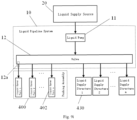
- the liquid spray port 402 is in communication with the liquid pipeline system 10 of the base station 100, and the liquid pipeline system 10 is further in communication with a liquid supply source 20 to deliver the cleaning liquid in the liquid supply source 20 to the liquid spray port 402.
- the liquid supply source 20 may be a clean water tank located on the base station body 110, or the liquid supply source 20 may be an external water source (e.g., tap water) independent of the base station 100.
- the liquid supply source 20 may be an external water source (e.g., tap water) independent of the base station 100.
- the cleaning liquid supplied from the liquid supply source 20 is conveyed to all the liquid spray ports 402 through the liquid pipeline system 10.
- the liquid outlet 114 of the base station 100 may also be used as a liquid spray port 402 for cleaning the sink 121.
- the liquid circuit system 10 further comprises a liquid pump 11 and a valve 12, and the liquid pump 11 is respectively in communication with the liquid supply source 20 and the valve 12.
- the valve 12 has at least two output ends 12a, and each liquid spray port 402 is in communication with one output end 12a.
- the plurality of liquid spray ports can be denoted as liquid spray port 1, liquid spray port 2, ..., liquid spray port n.
- the liquid pump 11 can regulate the pressure of the liquid sprayed from the plurality of liquid spray ports 402 by regulating the flow rate of the liquid, so as to meet the washing requirement in different dirt situations and make the automatic cleaning of the sink 121 more intelligent.
- the liquid pipeline system 10 may further provide other liquid supply functions.
- the liquid pipeline system 10 comprises at least one liquid supply structure 430, which is respectively denoted as liquid supply structure 1, liquid supply structure 2, ..., liquid supply structure m.
- the liquid supply structure 1 can be used to supply cleaning liquid into the sink 121 through the liquid outlet 114, so as to clean the cleaning assembly 510 of the self-moving cleaning device 500.
- the liquid supply structure 2 can be used to replenish liquid into the clean water tank.
- the plurality of liquid supply structures 430 can realize different liquid supply functions to meet different liquid supply requirements.
- the washing disk 120 further has an air outlet 125 in communication with the sink 121, and the air outlet 125 may be located on a side wall of a dock chamber 111 formed by the base station body 110, and/or the air outlet 125 may be located on a side wall of the sink 121.
- the air outlet 125 is configured to enable the airflow flowing to the sink 121 to pass there-through, and the airflow sprayed from the air outlet 125 can push the dirt in the sink 121 into at least one of the following: a preset area adjacent to the dirt outlet 122, the dirt outlet 122, the area adjacent to the drain outlet 124, and the drain outlet 124.
- One or a plurality of air outlets 125 may be provided.
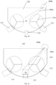
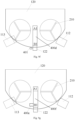
- "a plurality” means two or more. If only one air outlet 125 is provided, as shown in Fig. 9b , the air outlet 125 can be arranged to face the dirt outlet 122.
- the dashed box in the figure shows the approximate movement trajectory of the dirt conveyed from the air outlet 125 to the dirt outlet 122.
- the third fan blows air through the air outlet 125 to blow the dirt in the area A1 to an area B1, which is a preset area adjacent to the dirt outlet 122.
- the first fan 170 can operate, and can suck the dirt in an area B into the dust collection box 160 more conveniently, thus reducing the dirt remaining in the sink 121.
- a plurality of air outlets 125 may face the dirt outlet 122, or some air outlets 125 may not face the dirt outlet 122; the plurality of air outlets 125 may be arranged around a preset area or the dirt outlet 122 so as to jointly push the dirt to the dirt outlet 122.
- the base station 100 further comprises a fan device 400a for providing air flow to the air outlet 125, and the air flow generated by the fan device 400a is blasted to the sink 121 from the air outlet 125.
- the fan device 400a may utilize the second fan 191, or it may be a separate fan different from the second fan 191.
- the air outlet 125 and the liquid spray port 402 may be two separate outlets.
- the pipeline between the liquid spray port 402 and the fan may be opened, and the pipeline between the liquid spray port 402 and the liquid supply source 20 may be closed.
- the base station 100 further comprises: a pushing assembly 400 configured to push the dirt in the sink 121 into at least one of the following: a preset area adjacent to the dirt outlet 122, the dirt outlet 122, an area adjacent to the drain outlet 124, and the drain outlet 124.
- the pushing assembly 400 can push the dirt into the dirt outlet 122 or to the vicinity of the dirt outlet 122, so as to increase the possibility that the dirt is discharged from the dirt outlet 122, reduce the accumulation of the dirt in the sink 121, and further decrease the frequency of manual cleaning of the base station 100.
- the push assembly 400 may be mounted on the washing disk 120, or the push assembly 400 may be mounted on the base station body 110.
- the pushing assembly 400 can also push the dirt in the sink 121 to a preset area adjacent to the dust collection inlet 112 or into the dust collection inlet 112.
- the operation of pushing dirt by the pushing assembly 400 can be performed simultaneously with other operations of the base station 100, and/or may be a separate operation and is not performed simultaneously with other operations of the base station 100.
- Other operations of the base station 100 include at least one of the following: operation of cleaning the cleaning assembly 510 of the self-moving cleaning device 500 performed by the base station 100; and operation of collecting dirt in the sink 121 performed by the base station 100 when the dust collection assembly is in the first working mode.
- the pushing assembly 400 comprises a spray nozzle 410, with an outlet in communication with the sink 121, and the spray nozzle 410 is configured to spray the dirt in the sink 121 to at least one of the following by means of a fluid: a preset area adjacent to the dirt outlet 122, the dirt outlet 122, the area adjacent to the drain outlet 124, and the drain outlet 124.
- the fluid sprayed by the spray nozzle 410 can also wash away the dirt on the cleaning assembly 510 of the self-moving cleaning device 500, which is also beneficial for improving the cleaning effect of the cleaning assembly.
- the spray nozzle 410 is a structural member capable of spraying a liquid column, a liquid curtain or other forms of liquidous fluid.
- the position of the spray nozzle 410 is the same as that of the liquid spray port 402.
- the spray nozzle 410 may be inserted through the liquid spray port 402, and the liquid spray port 402 sprays liquid through the outlet of the spray nozzle 410.
- the position of the spray nozzle 410 is different from that of the liquid spray port 402.
- the spray nozzle 410 and the liquid spray port 402 are spaced apart from each other at different positions on the side wall of the sink 121.
- the liquidous fluid sprayed by the spray nozzle 410 may be a hot fluid heated by a heating mechanism. Compared with an unheated liquid, a hotter liquid can improve the solubility of oil stains, and further improve the removal effect of oily dirt in the sink 121.
- some spray nozzles 410 may spray liquid in a direction at an angle with respect to the orientation of the drain outlet 124 and/or the dirt outlet 122, and the angle may be any angle, such as 90°, 60°, 30° or 15°, etc.
- the plurality of spray nozzles 410 may be arranged around a preset area or the dirt outlet 122, so as to form a better surrounding effect on the preset area, which is beneficial for improving the dirt collection effect.
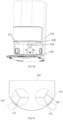
- Fig. 9c exemplarily shows one spray nozzle 410, which may be oriented to the dirt outlet 122, and the dashed box shows the approximate movement trajectory of the dirt conveyed from the spray nozzle 410 to the dirt outlet 122.
- the cleaning assemblies 510 of the self-moving cleaning device 500 most of the dirt in the sink 121 will be collected in an area A1 between the two cleaning assemblies 510, and the dirt in the area A1 can be purged by the fluid sprayed from the spray nozzle 410 to an area B1, which is a preset area adjacent to the dirt outlet 122.
- the first fan 170 can suck the dirt in the area B into the dust collection box 160 more conveniently, thus reducing the dirt remaining in the sink 121 and improving the cleaning effect for the sink 121.
- the spray nozzle 410 may be fixedly arranged with respect to the washing disk 120, or may be movably arranged with respect to the washing disk 120.
- the spray nozzle 410 may also be configured to be driven to move along a preset trajectory or in a second preset direction with respect to the washing disk 120.
- the spray nozzle 410 can expand the spraying range during the movement, so that the sprayed fluid can cover the sink 121 in a better way and the cleaning effect for the sink 121 can be improved.
- the movement of the spray nozzle 410 includes but is not limited to at least one of the following: translation, rotation or swing.
- the movement of the spray nozzle 410 in the second preset direction may be rotation in the horizontal direction, or rotation in the vertical direction perpendicular to the horizontal direction, or rotation in the horizontal direction and the vertical direction.
- the pushing assembly 400 further comprises a mounting bracket 420 mounted on the base station body 110, and the spray nozzle 410 is rotatably mounted on the mounting bracket 420, and is configured to be driven to rotate with respect to the mounting bracket 420 and spray liquid into the sink 121.
- the mounting bracket 420 may also be configured to be driven to move with respect to the base station body 110.
- Fig. 8g exemplarily shows the spray nozzle 410 mounted on the top wall of the dock chamber 111 of the base station body 110. It can be understood that the spray nozzle 410 may be mounted on a side wall of the dock chamber 111 alternatively.
- the spray nozzle 410 may be mounted on the washing disk 120.
- the base assembly of the washing disk 120 comprises a first base 120a and a second base 120b, wherein the second base 120b is mounted on a first surface of the first base 120a and has a sink 121, a second surface of the first base 120a has a bearing surface, and the base station 100 contacts with a supporting surface such as the ground by means of the bearing surface to realize the placement of the base station 100.
- the spray nozzle 410 is mounted on the first base 120a and located between the first base 120a and the second base 120b.
- the liquid sprayed by the spray nozzle 410 may come from the clean water tank in the base station 100, or the spray nozzle 410 may be separately provided with a liquid supply tank or a water supply source such as an external water source.
- the fluid sprayed by the spray nozzle 410 may be an airflow.
- the inlet of the spray nozzle 410 may be in communication with a third fan to realize an effect of spraying air from the spray nozzle 410.
- the third fan may employ the second fan 191 in the drying mode, or the third fan is another fan separate from the second fan 191 in the drying mode.
- the spray nozzle 410 is located at the same position as the air outlet 125.
- the spray nozzle 410 may be inserted through the air outlet 125, and the air outlet 125 sprays an airflow through the outlet of the spray nozzle 410.
- the position of the spray nozzle 410 is different from that of the air outlet 125.
- the spray nozzle 410 and the air outlet 125 are spaced apart from each other at different positions on the side wall of the sink 121.
- the pushing assembly 400 comprises a first driving assembly 400b and a mechanical arm 400c, wherein the mechanical arm 400c is connected to the first driving assembly 400b, and the first driving assembly 400b is configured to provide a driving force to the mechanical arm 400c; the mechanical arm 400c is configured to be driven by the first driving assembly 400b to push the dirt to a preset area adjacent to the dirt outlet 122.
- the first driving assembly 400b Before the first working mode of the dust collection pipeline is activated, the first driving assembly 400b can start operation. As shown in Fig. 9d , the first driving assembly 400b drives the mechanical arm 400c to extend into the area A1 and pick up the dirt; then, as shown in Fig. 9e , the mechanical arm 400c transports the picked dirt from the area A1 to an area B1, which is a preset area adjacent to the dirt outlet 122. After the first working mode of the dust collection pipeline is activated, the first fan 170 can operate, and can suck the dirt in an area B into the dust collection box 160 more conveniently, thus reducing the dirt remaining in the sink 121.
- the first driving assembly 400b comprises a first driving motor, or the first driving assembly 400b comprises a first driving motor and a first transmission element, and the power outputted by the first driving motor is transmitted by the first transmission element, and then the first transmission element drives the mechanical arm 400c to move.
- the first transmission element may be but is not limited to a transmission gear.
- the pushing assembly 400 comprises a second driving assembly 401, a rotating shaft (not shown) and a conveyor belt 400d, wherein the rotating shaft is connected to the second driving assembly 401, the conveyor belt 400d is connected to the rotating shaft, and the second driving assembly 401 can drive the rotating shaft to rotate, and the rotating shaft can drive the conveyor belt 400d to convey the dirt at a preset position in the sink 121 into the dirt outlet 122 or into a preset area adjacent to the dirt outlet 122.
- the preset position is usually a position in the sink 121 where the dirt may be retained easily.
- the preset position is an area A1 between two cleaning elements 512 of the self-moving cleaning device 500.
- One end of the conveyor belt 400d may cover the preset position, so that the dirt retained in the sink 121 is directly collected on the conveyor belt.
- the other end of the conveyor belt 400d may be located in the dirt outlet 122, so that when the second driving assembly 401 drives the conveyor belt 400d to operate, the conveyor belt 400d can directly convey the collected retained dirt into the dirt outlet 122, thereby the dirt can be cleaned more conveniently.
- the conveyor belt 400d may be flush with or slightly higher than the bottom wall of the sink 121, thereby the hinderance on the self-moving cleaning device 500 entering and leaving the dock chamber 111 can be reduced.
- a part of the conveyor belt 400d may be concealed under the cleaning bracket 200 to further reduce the interference with the self-moving cleaning device 500.
- the second driving assembly 401 comprises a second driving motor, or the second driving assembly 401 comprises a second driving motor and a second transmission element. After the power outputted by the second driving motor is transmitted by the second transmission element, the second transmission element drives the conveyor belt 400d to move.
- the second transmission element may be but is not limited to a transmission gear.
- the pushing assembly 400 further comprises a first driving mechanism 400e and a collecting member 400f, wherein a first end of the collecting member 400f is located at a preset position of the sink 121, and a second end of the collecting member 400f is located in a preset area adjacent to the dirt outlet 122, or the second end of the collecting member 400f is located in the dirt outlet 122; the first driving mechanism 400e is connected to one of the second end and the first end of the collecting member 400f, and is configured to drive one end of the collecting member 400f to ascend or descend, so that the second end of the collecting member 400f is lower than the first end, wherein the second end is an end opposite to the first end.
- the first driving mechanism 400e drives the collecting member 400f to descend, so that the second end of the collecting member 400f is lower than the first end, thereby the dirt on the first end can fall into the dirt outlet 122 by gravity or fall into an area adjacent to the dirt outlet 122.
- the collecting member 400f may comprise a structure such as a plate or a diaphragm.
- the first driving mechanism 400e is an air cylinder.
- the first driving mechanism 400e comprises a motor and a lead screw, and an input end of the lead screw is connected to an output end of the motor.
- the base station 100 may not comprise the pushing assembly 400.
- the base station 100 further comprises a second driving mechanism 400g and an extensible pipe 400h
- the base station body 110 has a clearance hole in communication with the dock chamber 111
- the extensible pipe 400h is inserted through the clearance hole, and is respectively in communication with the dock chamber 111 and the sink 121
- the second driving mechanism 400g is connected to a fixed end of the extensible pipe 400h, and a free end of the extensible pipe 400h can extend and retract with respect to the fixed end; the free end is the end opposite to the fixed end.
- the extensible pipe 400h is configured to enable the dirt flowing to the dust collection pipeline to pass there-through;
- the second driving mechanism 400g is configured to drive the extensible pipe 400h to switch between a retracted state and an extended state; when the dust collection pipeline is in the first working mode, the extensible pipe is in an extended state, and the free end of the extensible pipe is located at a preset position where dirt is accumulated in the sink 121 to collect the dirt in the sink 121; when the dust collection pipeline is in the second working mode, the extensible pipe is in a retracted state, there is spacing between the free end of the extensible pipe and the preset position, so as to reduce the effect on collecting the dirt in the dust cartridge 500 in the self-moving cleaning device.
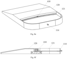
- Fig. 10a exemplarily shows a schematic partial structural diagram of the base station 100 when the extensible pipe 400h is in the retracted state
- Fig. 10b exemplarily shows a schematic partial structural diagram of the base station 100 when the extensible pipe 400h is in the extended state.
- the extensible pipe 400h when the extensible pipe 400h is in the extended state, the extensible pipe 400h can be closer to the dirt in the sink 121, and the dirt in the sink 121 can be more easily transported to the dust collection box 160 through the extensible pipe 400h, so as to reduce the frequency of manual cleaning of the washing disk 120.
- the extensible pipe 400h can be in the extended state, and the free end of the extensible pipe 400h is located in the area A1.
- the first fan 170 can operate, and can suck the dirt in the area A1 into the dust collection box 160 of the base station 100 more conveniently and reduce the dirt remaining in the sink 121.
- the projected free end of the extensible pipe 400h coincides with the preset position, and, at that point, it can be deemed that the free end of the extensible pipe 400h is at the preset position.
- the liquid pipeline system in an embodiment of the present disclosure is also used for conveying the dirt in the washing disk 120.
- the liquid pipeline system comprises a sewage inlet pipe 600 and a sewage tank 700, and a drain outlet 124 is located on the inner wall of the sink 121.
- the sewage inlet pipe 600 makes the drain outlet 124 and the sewage tank 700 communicate with each other, so as to convey the sewage in the sink 121 to the sewage tank 700 through the drain outlet 124.
- the inner diameter of the sewage inlet pipe 600 is greater than 40 mm, and the inner diameter of the drain outlet 124 is greater than or equal to that of the sewage inlet pipe 600.
- a sewage inlet pipe 600 having a larger inner diameter can alleviate the problem of blockage in the process of conveying sewage.
- the inner diameter of the sewage inlet pipe 600 is 40-50 mm.
- the inner diameter of the sewage inlet pipe 600 is 40 mm, 42 mm, 43 mm, 45 mm, 48 mm or 50 mm.
- the liquid pipeline system further comprises a fourth fan, an inlet of the fourth fan is in communication with the sewage tank 700, and the fourth fan is configured to provide driving force for introducing the fluid into the drain outlet 124 and conveying the fluid to the sewage tank 700 through the sewage inlet pipe 600.
- the fourth fan can suck the air in the sewage tank 700, so that the sewage tank 700 is in a negative pressure state, and then the sewage in the sink 121 can be sucked into the drain outlet 124, then enter the sewage inlet pipe 600 through the drain outlet 124, and then enter a sewage cavity through the sewage inlet pipe 600.
- the fourth fan may be a waterproof fan. In order to suck dirt having larger particle sizes in a better way, a high-power fan may be selected for the fourth fan.
- the liquid pipeline system further comprises a screw 610 and a third driving assembly 620, wherein the screw 610 is located in the sewage inlet pipe 600, and the screw 610 is configured to break the dirt in the sewage inlet pipe 600, and the third driving assembly 620 is configured to drive the screw 610 to rotate, so as to break the dirt entering the sewage inlet pipe 600 from the drain outlet 124.
- the screw 610 is located in the sewage inlet pipe 600, and the screw 610 is configured to break the dirt in the sewage inlet pipe 600
- the third driving assembly 620 is configured to drive the screw 610 to rotate, so as to break the dirt entering the sewage inlet pipe 600 from the drain outlet 124.
- the fluid entering the sewage inlet pipe 600 contains solid dirt having larger particle sizes, larger dirt particles can be broken into smaller dirt particles by the rotating screw 610.
- the base station 100 in this embodiment can alleviate the problem of blockage of dirt in the sewage inlet pipe 600, thereby the sewage inlet pipe 600 can be used to pick more dirt in the sink 121, thus reducing the retention of the dirt in the sink 121, which is beneficial for decreasing the frequency of manual cleaning of the washing disk 120.
- the rotating screw 610 not only has a function of breaking the dirt, but also can provide a driving force for the transportation of the dirt.
- the dirt in the sink 121 can be sucked into the sewage inlet pipe 600 by means of the screw 610, and no additional driving device is needed to suck the dirt from the sink 121. That is to say, if the base station 100 comprises the screw 610 and the third driving assembly 620, the aforesaid fourth fan may be omitted.
- the third driving assembly 620 comprises a third driving motor (not shown), or the third driving assembly 620 comprises a third driving motor and a third transmission element (not shown), the power outputted by the third driving motor is transmitted via the third transmission element, and the third transmission element drives the screw 610 to rotate.
- the third transmission element may be but is not limited to a transmission gear.
- the screw 610 may be coaxial with the sewage inlet pipe 600.
- the liquid pipeline system of the base station 100 further comprises: a sealing element 630, which is located between the third driving assembly 620 and the sewage inlet pipe 600, and is configured to realize a sealed connection between the third driving assembly 620 and the sewage inlet pipe 600, so as to prevent leakage of the dirt in the sewage inlet pipe 600.
- a sealing element 630 which is located between the third driving assembly 620 and the sewage inlet pipe 600, and is configured to realize a sealed connection between the third driving assembly 620 and the sewage inlet pipe 600, so as to prevent leakage of the dirt in the sewage inlet pipe 600.
- the base station 100 further comprises a sewage pipe 720 for draining the sewage in the sewage tank 700 and a sewage pump 710 for providing power for drainage, wherein an inlet of the sewage pipe 720 is in communication with the sewage tank 700, and an outlet of the sewage pipe 720 can be connected to a floor drain.
- a filter may also be provided in the sewage tank 700 to filter the fluid entering the sewage tank 700, and the filtered fluid is drained into the floor drain through the sewage pipe 720.
- the base station 100 further comprises cutters 900 and a fourth driving assembly 800 for driving the cutters 900 to rotate, wherein the cutters 900 are at least partially located in the sink 121, and are configured to break the dirt in the sink 121.
- the cutters 900 are at least partially located in the sink 121, and are configured to break the dirt in the sink 121.
- the dirt can be discharged from the drain outlet 124 and/or the dirt outlet 122 more easily, thus reducing the retention of the dirt in the sink 121.
- the cutters 900 may be distributed adjacent to the drain outlet 124, so that the broken dirt is less likely to flow into the drain outlet 124 due to dispersion, and the retention of the dirt in the sink 121 can be reduced.
- the cutter 900 comprises a cutter head 910 or grinding disc 920.
- the cutter head 910 usually has a holder and at least one blade mounted on the holder.
- the cutters 900 are located between the drain outlet 124 and the cleaning bracket 200.
- the height of the bottom wall 121a of the sink 121 gradually decreases in a direction from the side opposite to the dirt outlet 122 toward the dirt outlet 122, so that the dirt in the area where the cleaning bracket 200 is located can move to the dirt outlet 122 along the bottom wall 121a of the sink 121 under the action of gravity, thereby the dirt can be discharged more conveniently.
- the cutters 900 are arranged adjacent to the dirt outlet 122, and the dirt can move to the area where the cutters 900 are located along the bottom wall 121a of the sink 121 under the action of gravity, so that more dirt can be pushed to the cutters 900, and the cutters 900 can break more dirt.
- the sink 121 comprises a primary tank and a secondary tank that are in communication with each other, wherein the primary tank is configured to accommodate the cleaning assembly 510 of the self-moving cleaning device 500, the secondary tank is configured to accommodate the cutters 900, and the bottom wall of the secondary tank is located below the bottom wall of the primary tank, and both the drain outlet 124 and the dirt outlet 122 can be located on a side wall of the secondary tank.
- a side wall is adjacent to the bottom wall, and is perpendicular or approximately perpendicular to the bottom wall.
- the dirt in the primary tank can flow into the secondary tank at a lower position more easily, and the cutters 900 break the dirt in the secondary tank and further reduce the spreading of the broken dirt, so that more broken dirt can enter the drain outlet 124.
- the fourth driving assembly 800 comprises a fourth driving motor 810 and a fourth transmission element, wherein the fourth driving motor 810 drives the fourth transmission element to rotate, and the rotating fourth transmission element drives the cutters 900 to rotate.
- the fourth transmission element may be a transmission gear as shown in Fig. 13 or a worm 840 and a worm gear 850 as shown in Fig. 14 .
- the fourth driving assembly 800 may be located in a cavity inside the washing disk 120 (not in communication with the sink 121) or in a mounting slot outside the side wall of the washing disk 120, so as to limit the communication between the fourth driving assembly 800 and the sink 121 and reduce the effect of the dirt on the fourth driving assembly 800.
- the fourth driving motor 810 and the cutters 900 can be distributed vertically or approximately vertically, so that the fourth driving motor 810 can be adapted to the washing disk 120 having a smaller height, thereby the space of the washing disk 120 can be fully utilized.
- the fourth transmission element comprises a first bevel gear 820 and a second bevel gear 830, wherein the first bevel gear 820 is connected to an output end of the fourth driving motor 810, the second bevel gear 830 is meshed with the first bevel gear 820, and the second bevel gear 830 is connected to the cutters 900, and the axis of the first bevel gear 820 is perpendicular or approximately perpendicular to the axis of the second bevel gear 830.
- the fourth driving motor 810 drives the first bevel gear 820 to rotate, the first bevel gear 820 drives the second bevel gear 830 to rotate, and then the second bevel gear 830 drives the cutters 900 to break the dirt.
- the fourth transmission element comprises a worm gear 850 and a worm 840, wherein the worm 840 is connected to the output end of the fourth driving motor 810, and the worm gear 850 is meshed with the worm 840, connected to the cutters 900, and perpendicular or approximately perpendicular to the worm 840.
- the fourth driving motor 810 drives the worm 840 to rotate, the worm 840 drives the worm gear 850 to rotate, and then the worm gear 850 drives the cutters 900 to rotate to break the dirt.
- the sewage tank 700 may be located above the washing disk 120.
- the sewage tank 700 may be located below the sink 121, and is in communication with the drain outlet 124; the dirt in the sink 121 enters the sewage tank 700 through the drain outlet 124 under the action of gravity.
- the base station 100 having such a structure doesn't require the sewage inlet pipe 600, the fourth fan and the screw 610.
- the base station 100 may not comprise a liquid pipeline system; instead, the drain outlet 124 of the sink 121 is oriented to a floor drain, and the sewage in the sink 121 can be directly drained into the floor drain in the external environment through the drain outlet 124, so as to reduce the retention of the dirt in the sink 121.
- the base station 100 further comprises a protective sleeve, which is sleeved outside the washing disk 120 and configured to bear the dirt in the sink 121. If there is dirt in the sink 121, the dirt will be detained on the protective sleeve, and the washing disk 120 can be cleaned by replacing the protective sleeve regularly.
- a protective sleeve which is sleeved outside the washing disk 120 and configured to bear the dirt in the sink 121. If there is dirt in the sink 121, the dirt will be detained on the protective sleeve, and the washing disk 120 can be cleaned by replacing the protective sleeve regularly.
- the base station 100 further comprises: a collection box 30 for collecting the dirt, a second filter 40 and a sewage box 50, wherein the collection box 30 is in communication with the sink 121 to receive the dirt in the sink 121, the second filter 40 is located at the bottom of the collection box 30 to filter the dirt in the collection box 30, and the sewage box 50 is configured to receive the sewage filtered by the second filter 40, the inner wall of the sewage box 50 is provided with a drain outlet 124, and the sewage inlet pipe 600 is in communication with the drain outlet 124 to transport the sewage in the sewage box 50 to the sewage tank 700.
- the dirt in the sink 121 can flow to the collection box 30 and be filtered by the second filter 40, thereby larger particles that can't be filtered off remain in the collection box 30, while smaller particles can flow to the sewage box 50.
- the sewage pump 710 and the fourth fan can be turned on to suck the sewage in the sewage box 50 into the sewage inlet pipe 600, and then the sewage is conveyed to the sewage tank 700 through the sewage inlet pipe 600.
- the retention of the dirt in the sink 121 can be reduced, and the problem of blockage of the sewage inlet pipe by larger dirt particles entering the sewage inlet pipe 600 can be alleviated.
- the drying port 123 is located above the collection box 30, so that the drying airflow passing through the drying port 123 can dry the dirt in the collection box 30.
- the drying airflow can be used to dry the cleaning assembly 510 of the self-moving cleaning device 500 and dry the dirt in the collection box 30 as well, thereby reduce the odor of the dirt in the collection box 30 and prolong the storage time of the dirt in the collection box 30.
- the collection box 30 is detachably mounted on the washing disk 120.
- the control module of the base station 100 can remind the user to remove the collection box 30, so as to clean the dirt in the collection box 30 and improve the use experience.
- the height of the bottom wall of the sink 121 gradually decreases in a direction from the end away from the drain outlet 124 to the end close to the drain outlet 124.
- Such a gradient setting also enables the dirt in the sink 121 to flow into the collection box 30 by gravity, thereby the retention of the dirt in the sink 121 can be further reduced.
- the height of the bottom wall of the collection box 30 and/or the height of the bottom wall of the sewage box 50 gradually decreases in a direction from the end away from the drain outlet 112 to the end close to the drain outlet 124.
- Such a gradient setting is also beneficial to the flow of the sewage towards the drain outlet 124, thereby the sewage cleaning effect can be improved.
- the washing disk 120 further comprises an expansion base 120c for guiding the self-moving cleaning device 500 into of the base assembly, the base assembly has a sink 121 for accommodating the cleaning assembly 510, and the liquid pipeline system is at least used for conveying the dirt in the sink 121 to the sewage tank 700 or a floor drain; the expansion base 120c is provided with a first comb member (not shown) for scraping off the dirt on the cleaning assembly 510 of the self-moving cleaning device 500.
- the first comb member can remove at least a part of the dirt on the cleaning assembly 510, reduce the dirt entering the sink 121, thereby reduce the retention of the dirt in the sink 121.
- the washing disk 120 further comprises a vibrating member (not shown) mounted on the expansion base 120c, and the vibrating member causes the expansion base 120c to vibrate to shake off the dirt on the cleaning assembly 510 of the self-moving cleaning device 500 passing through the expansion base 120c, so as to reduce the dirt entering the sink 121.
- a vibrating member (not shown) mounted on the expansion base 120c, and the vibrating member causes the expansion base 120c to vibrate to shake off the dirt on the cleaning assembly 510 of the self-moving cleaning device 500 passing through the expansion base 120c, so as to reduce the dirt entering the sink 121.
- the gradient of the upper surface of the expansion base 120c that bears the self-moving cleaning device 500 gradually increases in a direction from the end away from the base assembly to the other end close to the base assembly.
- Such a slope setting can also make the end of the expansion base 120c away from the base assembly join to a supporting surface such as the ground, so as to effectively ensure that the self-moving cleaning device 500 can be guided into the base station 100 smoothly and safely.
- the washing disk 120 further comprises a first air outlet 61, an air duct structure 62 and an air blast device 60, which are located on the expansion base 120c, wherein the air duct structure 62 is in communication with the first air outlet 61, and the air blast device 60 provides an airflow to the first air outlet 61; the inner wall of the air duct structure 62 has a plurality of second air outlets for the airflow to pass there-through, and the second air outlets spray the airflow toward the cleaning assembly 510 of the self-moving equipment to blow off the dirt on the cleaning assembly 510.
- the air duct structure 61 may be located outside the sink 121; in the traveling direction of the self-moving cleaning device 500 to the base station 100, the sink 121 is located at the downstream, and the air duct structure is located at the upstream; thus, the air duct structure 61 can blow the dirt on the cleaning assembly out of the sink 121, thereby reduce the dirt entering the sink 121.
- the air blast device 60 may be but is not limited to a fan.
- the washing disk 120 further has a cavity 63 for containing dirt
- the air duct structure 62 can be located in the cavity 63, and the dirt blown off through the second air outlet of the air duct structure 62 can fall into the cavity 63; and the dirt in the cavity can be cleaned after the dirt is stored to a certain amount.
- the dirt blown off by means of the second air blast port on the air duct structure 62 will not be wetted by the cleaning liquid in the sink 121, the dirt falling in the cavity 63 is dry, and off-odor can be reduced.
- the air duct structure 62 may be located in the sink 121 alternatively.
- a cleaning system is provided in an embodiment of the present disclosure.
- the cleaning system comprises a base station 100 and a self-moving cleaning device 500, wherein the base station 100 comprises the base station 100 described in any of the above embodiments.
- the machine body 520 of the self-moving cleaning device 500 enters a dust suction mode in response to a cleaning instruction and starts the dust suction operation, thereby the dirt in the sink 121 enters the dust cartridge through the dust suction port on the machine body 520.
- the cleaning effect of the sink 121 can be improved.
- the cleaning assembly 510 of the self-moving cleaning device 500 comprises a roller brush 511 and a cleaning element 512, wherein the scraping range of the roller brush 511 is greater than or equal to that of the cleaning element 512. Owing to the differences between the roller brush 511 and the cleaning element 512 in terms of position, structure and material, dirt may be accumulated more easily on the cleaning element 512, when compared with the roller brush 511. By expanding the scraping range of the roller brush 511, the accumulation of dirt on the cleaning element 512 can be reduced, which is beneficial to reduce the dirt in the sink 121.
- the scraping range of the roller brush 511 can be extended in a variety of ways, including, but not limited to: increasing the length of the roller brush, or reducing the outside diameter of the mop.
- the self-moving cleaning device 500 further comprises a second comb member (not shown) for scraping the cleaning assembly 510.
- the second comb member may be mounted on the machine body 520 and disposed adjacent to the cleaning assembly 510. The second comb member interferes with the cleaning assembly 510 to remove at least a part of the dirt on the cleaning assembly 510 and reduce the dirt brought into the sink 121 by the cleaning assembly 510, thereby reduce the retention of the dirt in the sink 121.
- orientational or positional relationships indicated by orientational words such as “front”, “rear”, “upper”, “lower”, “left”, “right”, “horizontal”, “vertical”, “top” and “bottom”, etc. are usually based on the orientational or positional relationships shown in the accompanying drawings, and are used for the convenience of describing the present disclosure and simplifying the description. Unless otherwise stated, these orientational words do not indicate or imply that the devices or elements may have specific orientations or be constructed and operated in specific orientations; therefore, they shall not be understood as limiting the scope of protection of the present disclosure; orientational words “inside” and “outside” usually refer to inside and outside with respect to the outlines of the components.
- spatially relative terms such as “on top of”, “above”, “on” and “over”, etc. can be used herein to describe the spatial positional relationship between a device or feature and other devices or features as shown in the figures. It may be understood that the spatially relative terms are intended to include different orientations of the components in use or operation in addition to the orientations depicted in the drawings. For example, a device described as being “above” or “on top of” other devices or structures in the drawings will be positioned “below” or “under” other devices or structures when the devices are inverted. Thus, the illustrative term “above” can include orientations of “above” and “below”. The device may also be positioned in other different ways (e.g., rotated by 90 degrees or in other orientations), and the spatial relative description used herein may be explained accordingly.
Landscapes
- Cleaning By Liquid Or Steam (AREA)
- Sink And Installation For Waste Water (AREA)
Applications Claiming Priority (5)
| Application Number | Priority Date | Filing Date | Title |
|---|---|---|---|
| CN202222089230.2U CN218128421U (zh) | 2022-08-09 | 2022-08-09 | 清洁托盘、清洁基站及清洁系统 |
| CN202223563680.7U CN219483683U (zh) | 2022-12-30 | 2022-12-30 | 清洁装置、基站以及清洁系统 |
| CN202223600140.1U CN219541262U (zh) | 2022-12-30 | 2022-12-30 | 基站以及清洁系统 |
| CN202320163758.1U CN219699828U (zh) | 2023-02-08 | 2023-02-08 | 基站和清洁系统 |
| PCT/CN2023/112046 WO2024032667A1 (zh) | 2022-08-09 | 2023-08-09 | 基站及清洁系统 |
Publications (2)
| Publication Number | Publication Date |
|---|---|
| EP4555908A1 true EP4555908A1 (de) | 2025-05-21 |
| EP4555908A4 EP4555908A4 (de) | 2025-10-29 |
Family
ID=89850929
Family Applications (1)
| Application Number | Title | Priority Date | Filing Date |
|---|---|---|---|
| EP23851888.0A Pending EP4555908A4 (de) | 2022-08-09 | 2023-08-09 | Basisstation und reinigungssystem |
Country Status (2)
| Country | Link |
|---|---|
| EP (1) | EP4555908A4 (de) |
| WO (1) | WO2024032667A1 (de) |
Families Citing this family (4)
| Publication number | Priority date | Publication date | Assignee | Title |
|---|---|---|---|---|
| TW202537580A (zh) * | 2024-03-25 | 2025-10-01 | 大陸商北京石頭世紀科技股份有限公司 | 清潔基站及清潔系統 |
| WO2025201301A1 (zh) * | 2024-03-25 | 2025-10-02 | 北京石头世纪科技股份有限公司 | 清洁基站及清洁系统 |
| WO2025201309A1 (zh) * | 2024-03-25 | 2025-10-02 | 北京石头世纪科技股份有限公司 | 清洁基站及清洁系统 |
| WO2025214085A1 (zh) * | 2024-04-09 | 2025-10-16 | 北京石头世纪科技股份有限公司 | 一种流体处理装置及基站 |
Family Cites Families (17)
| Publication number | Priority date | Publication date | Assignee | Title |
|---|---|---|---|---|
| CN106618392B (zh) * | 2016-12-16 | 2019-02-26 | 云鲸智能科技(东莞)有限公司 | 清洁机器人和清洁机器人系统 |
| WO2021160055A1 (zh) * | 2020-02-14 | 2021-08-19 | 尚科宁家(中国)科技有限公司 | 一种用于电动拖把的清洗装置 |
| CN214048676U (zh) * | 2020-05-29 | 2021-08-27 | 深圳市银星智能科技股份有限公司 | 清洁基站以及清洁机器人系统 |
| CN111759240A (zh) * | 2020-06-22 | 2020-10-13 | 深圳市银星智能科技股份有限公司 | 自动洗拖布维护站 |
| CN111938526B (zh) * | 2020-08-13 | 2024-07-12 | 杭州匠龙机器人科技有限公司 | 一种扫拖机器人的集成站 |
| CN112353327B (zh) * | 2020-11-12 | 2025-07-15 | 深圳市杉川机器人有限公司 | 扫地机器人基站和清洁设备 |
| CN213993469U (zh) * | 2020-11-17 | 2021-08-20 | 深圳市杉川机器人有限公司 | 自动清洗结构和基站 |
| KR20220071810A (ko) * | 2020-11-24 | 2022-05-31 | 삼성전자주식회사 | 로봇 청소기와 도킹 스테이션을 포함하는 청소 장치 및 그 제어 방법 |
| CN215838722U (zh) * | 2021-02-06 | 2022-02-18 | 杭州匠龙机器人科技有限公司 | 一种清洁机器人系统 |
| CN115316883B (zh) * | 2021-05-11 | 2025-08-12 | 尚科宁家(中国)科技有限公司 | 一种用于清洁机器人的基站 |
| CN114711667A (zh) * | 2022-03-25 | 2022-07-08 | 深圳市优必选科技股份有限公司 | 清洁基站及表面清洁设备 |
| CN114766968A (zh) * | 2022-04-22 | 2022-07-22 | 小窝智能(北京)科技有限公司 | 一种清洁基站及清洁系统 |
| CN217524943U (zh) * | 2022-05-12 | 2022-10-04 | 尚科宁家(中国)科技有限公司 | 一种清洁系统 |
| CN217852794U (zh) * | 2022-06-20 | 2022-11-22 | 追觅创新科技(苏州)有限公司 | 基站 |
| CN115067834B (zh) * | 2022-06-24 | 2024-05-07 | 美智纵横科技有限责任公司 | 拖地机的拖布清洗组件、基座、拖地装置及其控制方法 |
| CN219483683U (zh) * | 2022-12-30 | 2023-08-08 | 追觅创新科技(苏州)有限公司 | 清洁装置、基站以及清洁系统 |
| CN115462717B (zh) * | 2022-08-10 | 2024-07-19 | 云鲸智能创新(深圳)有限公司 | 基站和清洁设备系统 |
-
2023
- 2023-08-09 WO PCT/CN2023/112046 patent/WO2024032667A1/zh not_active Ceased
- 2023-08-09 EP EP23851888.0A patent/EP4555908A4/de active Pending
Also Published As
| Publication number | Publication date |
|---|---|
| WO2024032667A1 (zh) | 2024-02-15 |
| EP4555908A4 (de) | 2025-10-29 |
Similar Documents
| Publication | Publication Date | Title |
|---|---|---|
| EP4555908A1 (de) | Basisstation und reinigungssystem | |
| CN112006615B (zh) | 一种清洁机器人的集成站 | |
| CN111973072B (zh) | 一种扫拖清洁机器人的集成站 | |
| CN111973073B (zh) | 一种智能扫拖清洁机器人的集成站 | |
| CN112006614B (zh) | 一种智能清洁机器人的集成站 | |
| CN111938526B (zh) | 一种扫拖机器人的集成站 | |
| CN111920349B (zh) | 一种拖吸机器人的集成站 | |
| CN216535171U (zh) | 清洁系统及基站 | |
| CN111973090B (zh) | 一种拖吸清洁机器人的集成站 | |
| CN218500623U (zh) | 基站 | |
| CN112401762A (zh) | 一种集成站及其清洁机器人系统 | |
| CN216876228U (zh) | 自移动清洁机器人及清洁系统 | |
| KR20190099407A (ko) | 베이스 스테이션 및 청소 로봇 시스템 | |
| EP4520242A1 (de) | Selbstfahrender reinigungsroboter, reinigungssystem, steuerungsverfahren und reinigungsverfahren | |
| CN111973091B (zh) | 一种智能扫拖机器人的集成站 | |
| JP2021122503A (ja) | 床面清掃装置 | |
| CN216535170U (zh) | 水箱及自移动清洁机器人 | |
| CN114668336A (zh) | 一种双清洁辊扫拖一体机器人及冲洗基座 | |
| KR20250163953A (ko) | 베이스 스테이션 및 청소 로봇 시스템 | |
| CN212591932U (zh) | 一种清洁机器人的集成站 | |
| CN212591928U (zh) | 一种智能扫拖清洁机器人的集成站 | |
| CN223392407U (zh) | 清洁基站及清洁系统 | |
| CN115153368A (zh) | 集尘基站 | |
| CN220477553U (zh) | 基站及清洁系统 | |
| CN216535172U (zh) | 滚筒组件及自移动清洁机器人 |
Legal Events
| Date | Code | Title | Description |
|---|---|---|---|
| STAA | Information on the status of an ep patent application or granted ep patent |
Free format text: STATUS: THE INTERNATIONAL PUBLICATION HAS BEEN MADE |
|
| PUAI | Public reference made under article 153(3) epc to a published international application that has entered the european phase |
Free format text: ORIGINAL CODE: 0009012 |
|
| STAA | Information on the status of an ep patent application or granted ep patent |
Free format text: STATUS: REQUEST FOR EXAMINATION WAS MADE |
|
| 17P | Request for examination filed |
Effective date: 20250213 |
|
| AK | Designated contracting states |
Kind code of ref document: A1 Designated state(s): AL AT BE BG CH CY CZ DE DK EE ES FI FR GB GR HR HU IE IS IT LI LT LU LV MC ME MK MT NL NO PL PT RO RS SE SI SK SM TR |
|
| REG | Reference to a national code |
Ref country code: DE Ref legal event code: R079 Free format text: PREVIOUS MAIN CLASS: A47L0011400000 Ipc: A47L0011283000 |
|
| A4 | Supplementary search report drawn up and despatched |
Effective date: 20250926 |
|
| RIC1 | Information provided on ipc code assigned before grant |
Ipc: A47L 11/283 20060101AFI20250922BHEP Ipc: A47L 11/40 20060101ALI20250922BHEP |
|
| DAV | Request for validation of the european patent (deleted) | ||
| DAX | Request for extension of the european patent (deleted) |