EP4520242A1 - Selbstfahrender reinigungsroboter, reinigungssystem, steuerungsverfahren und reinigungsverfahren - Google Patents
Selbstfahrender reinigungsroboter, reinigungssystem, steuerungsverfahren und reinigungsverfahren Download PDFInfo
- Publication number
- EP4520242A1 EP4520242A1 EP22894457.5A EP22894457A EP4520242A1 EP 4520242 A1 EP4520242 A1 EP 4520242A1 EP 22894457 A EP22894457 A EP 22894457A EP 4520242 A1 EP4520242 A1 EP 4520242A1
- Authority
- EP
- European Patent Office
- Prior art keywords
- roller
- cleaning
- self
- air duct
- moving
- Prior art date
- Legal status (The legal status is an assumption and is not a legal conclusion. Google has not performed a legal analysis and makes no representation as to the accuracy of the status listed.)
- Pending
Links
Images





Classifications
-
- A—HUMAN NECESSITIES
- A47—FURNITURE; DOMESTIC ARTICLES OR APPLIANCES; COFFEE MILLS; SPICE MILLS; SUCTION CLEANERS IN GENERAL
- A47L—DOMESTIC WASHING OR CLEANING; SUCTION CLEANERS IN GENERAL
- A47L11/00—Machines for cleaning floors, carpets, furniture, walls, or wall coverings
- A47L11/29—Floor-scrubbing machines characterised by means for taking-up dirty liquid
- A47L11/30—Floor-scrubbing machines characterised by means for taking-up dirty liquid by suction
-
- A—HUMAN NECESSITIES
- A47—FURNITURE; DOMESTIC ARTICLES OR APPLIANCES; COFFEE MILLS; SPICE MILLS; SUCTION CLEANERS IN GENERAL
- A47L—DOMESTIC WASHING OR CLEANING; SUCTION CLEANERS IN GENERAL
- A47L11/00—Machines for cleaning floors, carpets, furniture, walls, or wall coverings
- A47L11/24—Floor-sweeping machines, motor-driven
-
- A—HUMAN NECESSITIES
- A47—FURNITURE; DOMESTIC ARTICLES OR APPLIANCES; COFFEE MILLS; SPICE MILLS; SUCTION CLEANERS IN GENERAL
- A47L—DOMESTIC WASHING OR CLEANING; SUCTION CLEANERS IN GENERAL
- A47L11/00—Machines for cleaning floors, carpets, furniture, walls, or wall coverings
- A47L11/29—Floor-scrubbing machines characterised by means for taking-up dirty liquid
-
- A—HUMAN NECESSITIES
- A47—FURNITURE; DOMESTIC ARTICLES OR APPLIANCES; COFFEE MILLS; SPICE MILLS; SUCTION CLEANERS IN GENERAL
- A47L—DOMESTIC WASHING OR CLEANING; SUCTION CLEANERS IN GENERAL
- A47L11/00—Machines for cleaning floors, carpets, furniture, walls, or wall coverings
- A47L11/40—Parts or details of machines not provided for in groups A47L11/02 - A47L11/38, or not restricted to one of these groups, e.g. handles, arrangements of switches, skirts, buffers, levers
- A47L11/4013—Contaminants collecting devices, i.e. hoppers, tanks or the like
- A47L11/4016—Contaminants collecting devices, i.e. hoppers, tanks or the like specially adapted for collecting fluids
-
- A—HUMAN NECESSITIES
- A47—FURNITURE; DOMESTIC ARTICLES OR APPLIANCES; COFFEE MILLS; SPICE MILLS; SUCTION CLEANERS IN GENERAL
- A47L—DOMESTIC WASHING OR CLEANING; SUCTION CLEANERS IN GENERAL
- A47L11/00—Machines for cleaning floors, carpets, furniture, walls, or wall coverings
- A47L11/40—Parts or details of machines not provided for in groups A47L11/02 - A47L11/38, or not restricted to one of these groups, e.g. handles, arrangements of switches, skirts, buffers, levers
- A47L11/4013—Contaminants collecting devices, i.e. hoppers, tanks or the like
- A47L11/4025—Means for emptying
-
- A—HUMAN NECESSITIES
- A47—FURNITURE; DOMESTIC ARTICLES OR APPLIANCES; COFFEE MILLS; SPICE MILLS; SUCTION CLEANERS IN GENERAL
- A47L—DOMESTIC WASHING OR CLEANING; SUCTION CLEANERS IN GENERAL
- A47L11/00—Machines for cleaning floors, carpets, furniture, walls, or wall coverings
- A47L11/40—Parts or details of machines not provided for in groups A47L11/02 - A47L11/38, or not restricted to one of these groups, e.g. handles, arrangements of switches, skirts, buffers, levers
- A47L11/4027—Filtering or separating contaminants or debris
-
- A—HUMAN NECESSITIES
- A47—FURNITURE; DOMESTIC ARTICLES OR APPLIANCES; COFFEE MILLS; SPICE MILLS; SUCTION CLEANERS IN GENERAL
- A47L—DOMESTIC WASHING OR CLEANING; SUCTION CLEANERS IN GENERAL
- A47L11/00—Machines for cleaning floors, carpets, furniture, walls, or wall coverings
- A47L11/40—Parts or details of machines not provided for in groups A47L11/02 - A47L11/38, or not restricted to one of these groups, e.g. handles, arrangements of switches, skirts, buffers, levers
- A47L11/4072—Arrangement of castors or wheels
-
- A—HUMAN NECESSITIES
- A47—FURNITURE; DOMESTIC ARTICLES OR APPLIANCES; COFFEE MILLS; SPICE MILLS; SUCTION CLEANERS IN GENERAL
- A47L—DOMESTIC WASHING OR CLEANING; SUCTION CLEANERS IN GENERAL
- A47L11/00—Machines for cleaning floors, carpets, furniture, walls, or wall coverings
- A47L11/40—Parts or details of machines not provided for in groups A47L11/02 - A47L11/38, or not restricted to one of these groups, e.g. handles, arrangements of switches, skirts, buffers, levers
- A47L11/408—Means for supplying cleaning or surface treating agents
- A47L11/4083—Liquid supply reservoirs; Preparation of the agents, e.g. mixing devices
-
- A—HUMAN NECESSITIES
- A47—FURNITURE; DOMESTIC ARTICLES OR APPLIANCES; COFFEE MILLS; SPICE MILLS; SUCTION CLEANERS IN GENERAL
- A47L—DOMESTIC WASHING OR CLEANING; SUCTION CLEANERS IN GENERAL
- A47L7/00—Suction cleaners adapted for additional purposes; Tables with suction openings for cleaning purposes; Containers for cleaning articles by suction; Suction cleaners adapted to cleaning of brushes; Suction cleaners adapted to taking-up liquids
- A47L7/0004—Suction cleaners adapted to take up liquids, e.g. wet or dry vacuum cleaners
-
- A—HUMAN NECESSITIES
- A47—FURNITURE; DOMESTIC ARTICLES OR APPLIANCES; COFFEE MILLS; SPICE MILLS; SUCTION CLEANERS IN GENERAL
- A47L—DOMESTIC WASHING OR CLEANING; SUCTION CLEANERS IN GENERAL
- A47L7/00—Suction cleaners adapted for additional purposes; Tables with suction openings for cleaning purposes; Containers for cleaning articles by suction; Suction cleaners adapted to cleaning of brushes; Suction cleaners adapted to taking-up liquids
- A47L7/0004—Suction cleaners adapted to take up liquids, e.g. wet or dry vacuum cleaners
- A47L7/0019—Details of the casing
-
- A—HUMAN NECESSITIES
- A47—FURNITURE; DOMESTIC ARTICLES OR APPLIANCES; COFFEE MILLS; SPICE MILLS; SUCTION CLEANERS IN GENERAL
- A47L—DOMESTIC WASHING OR CLEANING; SUCTION CLEANERS IN GENERAL
- A47L7/00—Suction cleaners adapted for additional purposes; Tables with suction openings for cleaning purposes; Containers for cleaning articles by suction; Suction cleaners adapted to cleaning of brushes; Suction cleaners adapted to taking-up liquids
- A47L7/0004—Suction cleaners adapted to take up liquids, e.g. wet or dry vacuum cleaners
- A47L7/0023—Recovery tanks
- A47L7/0038—Recovery tanks with means for emptying the tanks
-
- A—HUMAN NECESSITIES
- A47—FURNITURE; DOMESTIC ARTICLES OR APPLIANCES; COFFEE MILLS; SPICE MILLS; SUCTION CLEANERS IN GENERAL
- A47L—DOMESTIC WASHING OR CLEANING; SUCTION CLEANERS IN GENERAL
- A47L9/00—Details or accessories of suction cleaners, e.g. mechanical means for controlling the suction or for effecting pulsating action; Storing devices specially adapted to suction cleaners or parts thereof; Carrying-vehicles specially adapted for suction cleaners
- A47L9/009—Carrying-vehicles; Arrangements of trollies or wheels; Means for avoiding mechanical obstacles
-
- A—HUMAN NECESSITIES
- A47—FURNITURE; DOMESTIC ARTICLES OR APPLIANCES; COFFEE MILLS; SPICE MILLS; SUCTION CLEANERS IN GENERAL
- A47L—DOMESTIC WASHING OR CLEANING; SUCTION CLEANERS IN GENERAL
- A47L9/00—Details or accessories of suction cleaners, e.g. mechanical means for controlling the suction or for effecting pulsating action; Storing devices specially adapted to suction cleaners or parts thereof; Carrying-vehicles specially adapted for suction cleaners
- A47L9/10—Filters; Dust separators; Dust removal; Automatic exchange of filters
- A47L9/14—Bags or the like; Rigid filtering receptacles; Attachment of, or closures for, bags or receptacles
- A47L9/1409—Rigid filtering receptacles
-
- A—HUMAN NECESSITIES
- A47—FURNITURE; DOMESTIC ARTICLES OR APPLIANCES; COFFEE MILLS; SPICE MILLS; SUCTION CLEANERS IN GENERAL
- A47L—DOMESTIC WASHING OR CLEANING; SUCTION CLEANERS IN GENERAL
- A47L9/00—Details or accessories of suction cleaners, e.g. mechanical means for controlling the suction or for effecting pulsating action; Storing devices specially adapted to suction cleaners or parts thereof; Carrying-vehicles specially adapted for suction cleaners
- A47L9/10—Filters; Dust separators; Dust removal; Automatic exchange of filters
- A47L9/14—Bags or the like; Rigid filtering receptacles; Attachment of, or closures for, bags or receptacles
- A47L9/1427—Means for mounting or attaching bags or filtering receptacles in suction cleaners; Adapters
- A47L9/1463—Means for mounting or attaching bags or filtering receptacles in suction cleaners; Adapters specially adapted for rigid filtering receptacles
-
- A—HUMAN NECESSITIES
- A47—FURNITURE; DOMESTIC ARTICLES OR APPLIANCES; COFFEE MILLS; SPICE MILLS; SUCTION CLEANERS IN GENERAL
- A47L—DOMESTIC WASHING OR CLEANING; SUCTION CLEANERS IN GENERAL
- A47L9/00—Details or accessories of suction cleaners, e.g. mechanical means for controlling the suction or for effecting pulsating action; Storing devices specially adapted to suction cleaners or parts thereof; Carrying-vehicles specially adapted for suction cleaners
- A47L9/22—Mountings for motor fan assemblies
-
- A—HUMAN NECESSITIES
- A47—FURNITURE; DOMESTIC ARTICLES OR APPLIANCES; COFFEE MILLS; SPICE MILLS; SUCTION CLEANERS IN GENERAL
- A47L—DOMESTIC WASHING OR CLEANING; SUCTION CLEANERS IN GENERAL
- A47L2201/00—Robotic cleaning machines, i.e. with automatic control of the travelling movement or the cleaning operation
-
- A—HUMAN NECESSITIES
- A47—FURNITURE; DOMESTIC ARTICLES OR APPLIANCES; COFFEE MILLS; SPICE MILLS; SUCTION CLEANERS IN GENERAL
- A47L—DOMESTIC WASHING OR CLEANING; SUCTION CLEANERS IN GENERAL
- A47L2201/00—Robotic cleaning machines, i.e. with automatic control of the travelling movement or the cleaning operation
- A47L2201/04—Automatic control of the travelling movement; Automatic obstacle detection
Definitions
- This disclosure relates to the field of robotics, particularly focusing on a self-moving cleaning robot. Additionally, it relates to a cleaning system comprising the aforementioned self-moving cleaning robot, along with control methods and cleaning methods.
- the self-moving floor cleaning robot is an intelligent household appliance capable of autonomously performing cleaning tasks such as sweeping, vacuuming, and mopping within a room, relying on a certain level of artificial intelligence.
- the present disclosure provides a self-moving cleaning robot, a cleaning system, a control method, and a cleaning method.
- a self-moving cleaning robot comprising a body and a water tank mounted on the body.
- the water tank comprises:
- a water tank comprising:
- a self-moving cleaning robot comprising a body and a water tank assembly disposed in the body.
- the water tank assembly comprises: a clean water tank; a sewage tank with an air inlet; a fan chamber, wherein the opening of the fan chamber faces the bottom of the water tank assembly, and the fan assembly is inserted into the fan chamber from the opening.
- the top of the fan chamber is provided with an air outlet communicating with the sewage tank.
- a second channel is provided between the clean water tank and the fan chamber to allow the airflow entering the sewage tank from the air inlet to be discharged through the air outlet via the second channel.
- One beneficial effect of the present disclosure is that, during the operation of the self-moving robot, negative pressure is generated in the air duct, which can suck the sewage generated during the cleaning work from the air inlet into the tank body.
- the first channel space of the tank body is relatively open, allowing sewage and airflow to be adequately separated in the first channel.
- the sewage remains in the inner cavity of the tank body, while the airflow uniformly flows towards the air outlet through the second channel inside the tank body and is discharged, preventing the situation where the sewage is carried away by excessively fast local airflow.
- a self-moving cleaning robot comprising a body and, mounted on the body:
- a cleaning system comprising a self-moving cleaning robot and a base station.
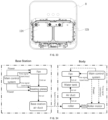
- the base station includes a base station body with a housing cavity, and a drying system is installed inside the base station body.
- the housing cavity of the base station body is constructed to accommodate the self-moving cleaning robot.
- the inlet of the first air duct of the self-moving cleaning robot is configured to draw in the wind drying airflow emitted by the drying system, drying the cleaning device.
- the first air duct located at the rear of the cleaning device, can suction away sewage from behind the cleaning device.
- the sewage suctioned by the air duct can be separated from gas in the second air duct of the sewage tank, avoiding entry into the third air duct and affecting the fan assembly. This ensures efficient utilization of energy by the fan assembly, thereby improving work efficiency.
- a self-moving cleaning robot comprising a body with a mounting cavity and a roller assembly mounted in the mounting cavity.
- the roller assembly comprises:
- a roller assembly comprising:
- One beneficial effect of this disclosure is that, in the roller assembly of the self-moving cleaning robot, the pressure block at one end of the roller can be sealed against the end face of the roller bracket, and under the action of the elastic device, the pressure block can be moved axially along the side wall of the roller cavity of the roller bracket to ensure the sealing performance between them, facilitating the assembly and disassembly of the roller.
- a self-moving floor scrubbing robot comprising:
- a control method for the robot is also provided, wherein the robot employs the self-moving floor scrubbing robot; further comprising an identification device and a control unit, comprising the following steps:
- An advantageous effect of this disclosure is that the squeegee scrapes away sewage from the roller while the roller cleans the working surface, thus enhancing the cleaning ability of the roller.
- the roller and the squeegee undergo relative movement, causing the squeegee to stop scraping water to prevent sewage from remaining on the floor.
- a cleaning system comprising:
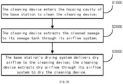
- a cleaning method is provided, implemented by a cleaning system, comprising:
- a base station comprising:
- An advantageous effect of the present disclosure is that after the cleaning device enters the housing cavity of the base station, the air duct system can extract dry airflow sent out by the base station's drying system, drying the cleaning unit and the residual water stains inside the cleaning device, preventing bacteria growth and odor.
- a water tank comprising a body and a water tank mounted on the body, wherein the water tank comprises:
- a water tank comprising a body and a water tank mounted on the body, wherein the water tank comprises:
- An advantageous effect of the present disclosure is that the airflow in the air duct affects the liquid water level in the cavity of the water tank, causing the liquid to be pushed towards the air outlet.
- the water baffle inside the water tank, located adjacent to the air outlet on the inner wall of the body, can block the raised water level, preventing liquid from being drawn out of the water tank from the air outlet. Additionally, the water baffle has through-holes, allowing airflow in the air duct to flow towards the air outlet.
- body 1 floating part 11-A, fixed part 11-B, mounting cavity 101, clean water interface 102, waterless detection sensor 103, limiting slot 1011, hinge shaft 120, universal wheel 13, cliff sensor 14, tank groove 15, battery 16, battery mounting bracket 160, connecting line 161, lifting part 17, support base 18, shaft pressure cover 19, roller assembly 2, roller 20, assembly groove 200, drive assembly 21, rotating part 210, pressure block 22, anti-rotation portion 221, elastic device 23, base component 24, roller shaft end cover 241, first screw socket 2410, guide rod 2411, fixed seat 242, second screw socket 2420, roller end cover 243, flange 2431, anti-rotation structure 2432, rotating shaft 25, bearing 26, positioning structure 27, roller bracket 28, anti-rotation groove 280, avoidance space 281, locking slot 282, limit buckle 283, side wall 284, roller cover plate 29, slider 291, locking member 292, coupling portion 2920, first air duct 31, first air outlet 310, second air duct 32, second air inlet 320, second air outlet 32
- Cleaning equipment includes floor cleaning machine, vacuum cleaners, and floor-sweeping robots, which play an efficient cleaning role in various places such as municipal sanitation, manufacturing workshops, and indoor environments, reducing the labor cost of cleaning, improving work efficiency, and are indispensable equipment in modern society.
- Self-moving floor cleaning robots are a type of cleaning equipment that can automatically complete cleaning, vacuuming, mopping, and other cleaning tasks in a room with certain artificial intelligence.
- Existing self-moving floor cleaning robots clean the floor using a roller, with an air inlet at the rear of the roller to suction away water stains. After using for a period of time, the roller needs to be removed for cleaning.
- the existing self-moving cleaning robot's roller is inconvenient to disassemble and install with the body, and there is a problem of poor sealing, resulting in significant loss of suction power at the rear air inlet, making it easy for water stains to remain on the floor. The water stains will continue to adhere to dust, causing secondary pollution, reducing cleaning efficiency, and causing people to slip on the floor due to water stains when walking.
- the present disclosure provides a self-moving cleaning robot, comprising a body capable of walking on a working surface with the assistance of a control unit.
- a cleaning device is arranged on the body, and the cleaning device is configured to clean the working surface.
- the self-moving cleaning robot can be a floor-sweeping robot, and the working surface to be cleaned can be the floor.
- the body also includes an air duct, a sewage tank, and a fan assembly.
- the air duct includes a first air duct, the entrance of which is adjacent to the cleaning device and is configured to extract sewage from the working surface after cleaning by the cleaning device.
- the sewage tank is configured to contain the sewage from the working surface after cleaning.
- the sewage tank is provided with a second air duct, and the fan assembly has a third air duct.
- the first air duct and the third air duct are respectively connected to the second air duct; the fan assembly is able to provide negative pressure to the three air ducts, and the water vapor extracted by the first air duct enters the second air duct of the sewage tank, where the liquid drops into the sewage tank, and the gas is discharged through the suction passage of the fan assembly.
- the first air duct is relatively narrow, so the airflow speed in the first air duct is higher, which can suction away the sewage after cleaning the working surface.
- the second air duct in the sewage tank is relatively wide. After the water vapor in the first air duct enters the second air duct, the flow rate decreases, the air pressure decreases, and the heavier sewage is separated from the gas and remains in the sewage tank, while the separated gas is sucked into the third air duct.
- the exemplary embodiment of the present disclosure takes the direction of movement of the body as the forward direction.
- the cleaning device is arranged near the front of the body, and the fan assembly is arranged near the rear of the body.
- the first air duct is set behind the cleaning device, and the sewage tank is set between the first air duct and the fan assembly, so that the first air duct, the second air duct, and the third air duct have a longer path, which is conducive to the sufficient separation of water vapor in the second air duct of the sewage tank.
- the air outlet of the fan assembly faces the working surface, blowing the working surface cleaned by the cleaning device to accelerate the evaporation of residual water stains.
- the heat generated by the fan assembly itself can heat the airflow, accelerating the evaporation of water stains on the working surface, fully utilizing the energy of the fan assembly.
- the body also includes a clean water tank for storing clean water, cleaning agents, and other cleaning liquids.
- the clean water tank is configured to supply the cleaning liquid to the cleaning device to enhance the decontamination ability of the cleaning device and improve the efficiency of the self-moving cleaning robot.
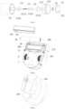
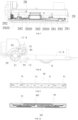
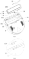
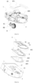
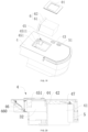
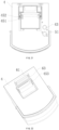
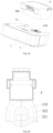
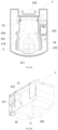
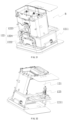
- FIGS. 1 to 27 show specific embodiments of the self-moving cleaning robot of the present disclosure, including the body 1, which is provided with a cleaning device, air ducts, sewage tank 4, clean water tank 5, and fan assembly 7.
- the air duct includes the first air duct 31 set on the body 1, the second air duct 32 set in the sewage tank 4 and connected to the first air duct 31, and the third air duct 33 set in the fan assembly 7 and connected to the second air duct 32.
- the cleaning device is arranged at the front of the body 1, and the entrance of the first air duct 31 is set behind the cleaning device and faces the working surface.
- the entrance of the first air duct 31, the cleaning device, and the working surface form a relatively enclosed space, and the fan assembly 7 rotates to create negative pressure, thereby forming an airflow in the air duct flowing from the cleaning device towards the outlet of the fan assembly 7, allowing the first air duct 31 to suction away the sewage after cleaning the working surface by the cleaning device.
- the air duct not only can suction away sewage but also solid particles on the working surface. When the sewage contains mixed solid particles, the first air duct 31 can suction away both sewage and solid particles simultaneously.
- the bottom of the body 1 is also provided with driving wheels 8 for walking, and the driving wheels 8 are set behind the cleaning device.
- the cleaning device can clean dirt, water stains, etc., on the working surface in front of the driving wheels 8 during walking to prevent dust and water stains from affecting the friction between the driving wheels 8 and the working surface, thereby protecting the driving wheels 8 and improving the mobility of the body 1.
- the cleaning device may include a mop, brush, roller brush, roller, etc., capable of wiping or sweeping the working surface while the body 1 is walking.
- the cleaning device includes a roller 20, and a mounting cavity is provided on the body 1.
- the roller 20 is rotatably connected in the mounting cavity of the body 1 and can roll against the working surface.
- the surface of the roller 20 can be provided with a cleaning layer, which can be a sponge, cotton cloth, velvet, etc. During rolling, the cleaning layer can wipe the working surface and adhere to dust and other stains on the working surface.
- the roller 20 can be designed as a hollow structure to reduce weight.
- the roller 20 can achieve rolling in different ways. In some embodiments, the roller 20 can rotate by relying on the friction between the body 1 and the working surface during walking; in other embodiments, the roller 20 can rotate by the driving action of a driving mechanism.
- a drive assembly 21 is provided on the body 1, and the drive assembly 21 is connected to the roller 20 to drive the rotation of the roller 20.
- the drive assembly 21 includes a motor and a transmission mechanism. The output end of the motor is connected to one end of the roller 20 through the transmission mechanism to drive the rotation of the roller 20.
- one end of the roller 20 can be set to detachably connect with the drive assembly 21, and the other end can be set to detachably rotate with the body 1. Furthermore, in order to reduce the wind loss at the entrance of the first air duct 31, the two end portions of the roller 20 and the corresponding positions of the body 1 are sealed.
- the roller 20 is installed on the body 1 in the form of a roller assembly 2.
- the roller assembly 2 includes a roller bracket 28, a roller 20 mounted on the roller bracket 28, and a roller cover plate 29 that restricts the roller 20 on the roller bracket 28.
- a mounting cavity 101 is provided at a corresponding position on the body 1, and the shape of the mounting cavity 101 matches the shape of the roller assembly 2. This allows the roller assembly 2 to be installed in the mounting cavity 101 of the body 1, and allows the roller 20 to extend out of the lower end surface of the body 1 for fitting with the working surface. The roller 20 can clean the working surface by rotating.
- the roller bracket 28 can have a frame-shaped or slot-shaped structure, with a roller cavity provided on the roller bracket 28.
- the roller 20 is rotatably connected in the roller cavity
- the roller cover plate 29 is frame-shaped, mounted on the open end of the roller bracket 28, and restricts the roller 20 in the roller cavity of the roller bracket 28, with part of the roller 20 extending out from the frame of the roller cover plate 29 for contact with the working surface.
- the drive assembly 21 can be directly or indirectly connected to the rotating part 210 set inside the roller bracket 28 through a transmission mechanism.
- One end of the roller 20 is provided with an assembly groove 200 for assembly with the rotating part 210 to drive the rotation of the roller 20.
- the rotating part 210 can be provided with flanges and/or groove structures to cooperate with corresponding flanges and/or groove structures in the assembly groove 200.
- the roller bracket 28 is provided with a yielding structure, such as an avoidance groove, at one end for cooperation with the transmission mechanism.
- the avoidance groove, etc., rotating part 210 is rotationally connected to the main body and is connected to the transmission mechanism.
- the yielding structure at the corresponding position of the roller bracket 28 can directly pass through the rotating part 210, thereby installing the roller bracket 28 in the mounting cavity 101 of the body 1. This is not specifically described here.
- the other end of the roller 20 can be sealed connected to the end face of the roller bracket 28 by means of pressure blocks 22.
- one end of the roller 20 is provided with pressure blocks 22, which are preloaded at one end of the roller 20 through elastic devices 23.
- the outer end face of the pressure block 22 abuts against the corresponding end face of the roller cavity on the roller bracket 28, and under the action of the elastic device 23, the outer end face of the pressure block 22 forms a contact seal with the end face of the roller cavity.
- the roller 20 is also rotatably connected to the roller bracket 28 through the pressure block 22.
- the pressure block 22 can be rotatably connected to the roller bracket 28 or the roller 20.
- the roller 20 also includes a base component 24 and a rotating shaft 25 supported inside the roller 20.
- the base component 24 is relatively fixed to the roller 20, and the axial direction of the base component 24 is consistent with the axial direction of the roller 20.
- the rotating shaft 25 is configured to move along the axial direction of the base component 24.
- the rotating shaft 25 is rotationally connected to the pressure block 22, and under the action of the elastic device 23, the rotating shaft 25 applies outward pressure to the pressure block 22, driving the pressure block 22 to tightly adhere to the inner wall of the roller cavity, achieving sealing between them.
- the base component 24 can be made of self-lubricating material to reduce friction between the rotating shaft 25 and the base component 24, thus extending the service life.
- the base component 24 includes roller end covers 243 for supporting inside the roller 20 and fixed seats 242 fixed on the roller end covers 243.
- the rotating shaft 25 passes through the fixed seat 242 and is configured to move along the axial direction of the roller 20.
- the fixed seat 242 extends axially relative to the roller 20, and a guiding channel is provided inside the fixed seat 242.
- the rotating shaft 25 is arranged in the guiding channel of the fixed seat 242. When the rotating shaft 25 is subjected to external force, it can move along the extension direction of the fixed seat 242, thereby improving the stability of the rotating shaft 25.
- the base component 24 also includes roller shaft end covers 241 connected to the fixed seat 242 or the roller end covers 243, and the elastic device 23 is arranged between the rotating shaft 25 and the roller shaft end covers 241.
- the elastic device 23 preloads the pressure block 22 against the end face of the mounting cavity through the rotating shaft 25.
- the roller shaft end covers 241 can be designed in a "concave” structure, and the elastic device 23 is arranged inside the roller shaft end covers 241.
- the roller shaft end covers 241, fixed seats 242, and roller end covers 243 of the base component 24 can be connected from the inside to the outside of the roller 20. These components can be integrally processed or set as separate connection structures.
- the connection methods of the separate connection structure include but are not limited to threaded connection, screw connection, adhesive bonding, and insertion connection.
- the roller shaft end covers 241, fixed seats 242, and roller end covers 243 of the base component 24 adopt a modular connection structure to facilitate the installation of the elastic device 23 and the rotating shaft 25.
- Positioning structures 27 are provided between the roller shaft end covers 241 and the fixed seats 242, and between the fixed seats 242 and the roller end covers 243, allowing for convenient positioning during installation.
- the roller shaft end covers 241, fixed seats 242, and roller end covers 243 can be further secured by screws to enhance connection stability. Screw holes or screw sockets can be provided on the roller shaft end covers 241, fixed seats 242, and roller end covers 243 for screw insertion.
- the roller shaft end covers 241 are provided with first screw sockets 2410 on opposite sides
- the fixed seats 242 are provided with second screw sockets 2420 on opposite sides
- threaded holes can be provided on the roller end covers.
- the threaded holes, first screw sockets 2410, and second screw sockets 2420 are coaxially aligned. Screws pass through the threaded holes, first screw sockets 2410, and second screw sockets 2420 to securely connect the roller shaft end covers 241, fixed seats 242, and roller end covers 243 together.
- the fixed seats 242 can be manufactured separately using self-lubricating materials, while the roller shaft end covers 241 and roller end covers 243 can be made from other common materials to save costs.
- the elastic device 23 can be selected from compression springs, elastic plates, elastic blocks, etc.
- a compression spring is used for the elastic device 23.
- the compression spring can be connected to the roller shaft end covers 241 and the rotating shaft 25 using a plug-in mating connection method.
- Guide structures compatible with the compression spring can be provided on the roller shaft end covers 241 and/or the rotating shaft 25, such as guide rods, guide sleeves, etc., to guide the compression spring and improve its installation stability.
- One end of the rotating shaft 25 connected to the elastic device 23 can extend into the roller shaft end cover 241 and be set as a limiting end, which can abut against the end face of the fixed seat 242 to restrict the position of the rotating shaft 25 and prevent it from detaching from the fixed seat 242.
- the radial size of the roller shaft end cover 241 is sufficient to accommodate the limiting end of the rotating shaft 25. Under external force, the rotating shaft 25 can move axially into the roller shaft end cover 241.
- the roller end cover 243 can be close to the end face of the roller 20 and be shaped to match the "concave" structure of the pressure block 22.
- the roller end cover 243 is provided with a cavity to accommodate the pressure block 22, and a limiting structure is formed between the outer circumference of the pressure block 22 and the inner wall of the cavity of the roller end cover 243 to prevent the pressure block 22 from escaping from the cavity of the roller end cover 243.
- the pressure block 22 can move axially along the axis of the roller, and one end of the rotating shaft 25 passes through the roller end cover 243 to rotatably connect with the pressure block 22. Under the driving force of the elastic device 23, the pressure block 22 partially extends from the roller end cover 243 and mates with the corresponding position of the roller bracket 28.
- the outer end face of the pressure block 22 can be provided with grooves and/or protrusions for external connection, which mate with corresponding grooves or protrusions set on the end face of the roller bracket.
- the grooves and/or protrusions should be offset from the center position of the pressure block 22 or set to a non-circular shape.
- the outer side of the pressure block 22 is equipped with an outwardly extending anti-rotation portion 221, and the inner wall of the roller cavity is provided with an anti-rotation groove 280 that mates with the anti-rotation portion 221, the anti-rotation groove 280 can be configured to match the shape of the anti-rotation portion 221.
- the anti-rotation portion 221 fits into the anti-rotation groove 280, preventing the pressure block 22 from rotating with the roller 20.
- the anti-rotation portion 221 After inserting it into the anti-rotation groove 280, under the action of the elastic device 23, the anti-rotation portion 221 is pressed against the side wall of the anti-rotation groove 280. Finally, the anti-rotation portion 221 is constrained in the anti-rotation groove 280 by the roller cover plate 29 to prevent it from coming out of the anti-rotation groove 280.
- the roller cover plate 29 can be connected to the body 1 or the roller bracket 28.
- the roller cover plate 29 is detachably connected, with specific connection methods including but not limited to screw fixation, insertion, and snap connection.
- the roller cover plate 29 can be detachably connected to the roller bracket 28.
- a slider 291 is arranged on the roller cover plate 29.
- the slider 291 is configured to slide fit on the outer side of the roller cover plate 29, and a locking member 292 is further provided on the rear or back of the roller cover plate 29.
- the locking member 292 cooperates with the slider 291, allowing users to move the locking member 292 located at the rear or back of the roller cover plate 29 by manipulating the slider 291 on the outer side of the roller cover plate 29.
- the slider 291 can be guided to fit into the corresponding guide groove set on the roller cover plate 29, and is preloaded to the first position by the elastic device.
- the locking member 292 can cooperate with the slider 291 through a groove or other known means in the art, enabling the locking member 292 to move synchronously with the slider 291.
- a coupling portion 2920 can be provided on the locking member 292, for example, at the end position of the locking member 292 or at any other suitable position.
- the locking member 292 is located in the avoidance space 281 of the roller bracket 28, allowing users to move the locking member 292 within the avoidance space 281 of the roller bracket 28 by manipulating the slider 291.
- Corresponding positions on the roller bracket 28 are provided with locking slot 282 for cooperating with the coupling portions 2920 of the locking member 292, such that when the slider 291 moves from the second position to the first position, the coupling portions 2920 of the locking member 292 can move into alignment with the locking slot 282 of the roller bracket 28 to securely engage the roller cover plate 29 with the roller bracket 28.
- the coupling portions 2920 can be maintained in engagement with the locking slot 282.
- the slider 291 When it is necessary to remove the roller cover plate 29, the slider 291 is driven to move from the second position to the first position, causing the coupling portions 2920 of the locking member 292 to disengage from the locking slot 282 of the roller bracket 28. Then, the roller cover plate 29 can be removed from the roller bracket 28, allowing access to the corresponding components for replacement or maintenance, such as replacing or maintaining the roller 20.
- Multiple coupling portions 2920 can be provided on the locking member 292, spaced apart along the extension direction of the roller cover plate 29; correspondingly, multiple locking slot 282 can be provided on the roller bracket 28, thus ensuring multiple locking structures along the extension direction of the roller bracket 28 and the roller cover plate 29, ensuring the stability of the connection between the two.
- the pressure block 22 When installing the roller 20, the pressure block 22 is moved a certain distance towards the inside of the roller 20, so that the elastic device 23 generates a preloading force on the pressure block 22. Then, the roller 20 is inserted into the roller bracket 28, and the pressure block 22 of the roller is pressed against the corresponding end face of the roller bracket 28 under the action of the elastic device 23, thus achieving sealing. After the roller 20 is installed, the roller cover plate 29 is mounted on the roller bracket 28, and the slider 291 of the roller cover plate 29 is engaged with the corresponding guide groove of the roller bracket 28.
- the slider 291 is pushed from the first position to the second position, causing the locking member 292 on the roller cover plate 29 to move, and the coupling portion 2920 of the locking member 292 is brought into alignment with the locking slot 282 on the roller bracket 28, thereby securely engaging the roller cover plate 29 with the roller bracket 28, and the roller 20 is confined between the roller bracket 28 and the roller cover plate 29.
- the slider 291 When disassembling the roller 20, the slider 291 is driven to move from the second position to the first position, causing the coupling portion 2920 of the locking member 292 to disengage from the locking slot 282 of the roller bracket 28. Then, the roller cover plate 29 is removed, followed by the removal of the roller 20 from the roller bracket 28.
- An auxiliary cleaning component 9 is also provided on the body 1, as shown in FIGS. 1 and 8 .
- the auxiliary cleaning component 9 is positioned near the roller 20 and assists in the cleaning work of the roller 20, thereby improving the cleaning efficiency of the roller 20.
- the auxiliary cleaning component 9 includes a nozzle 91, which is oriented towards the roller 20 and is configured to spray water onto the surface of the roller 20.
- the nozzle 91 can be positioned behind the cleaning device and above the entrance of the first air duct 31.
- the nozzle 91 can be singular or multiple, and when multiple, they can be arranged along the axial direction of the roller 20.
- the nozzle 91 can be a misting nozzle, which sprays the cleaning liquid more uniformly and conserves the consumption rate of the cleaning liquid.
- the nozzles 91 are equipped with multiple units, and these multiple units are integrated and set on the water supply device 90.
- the water supply device 90 can be a plate-like structure parallel to the roller 20. Additionally, the water supply device 90 is equipped with a main water inlet 901 and multiple water supply channels 902. The main water inlet 901 is connected to the clean water tank 5, and the multiple nozzles 91 are connected to the main water inlet 901 through the water supply channels 902. The clean water from the clean water tank 5 is supplied to the nozzles 91 via the main water inlet 901 and the water supply channels 902. Multiple water supply channels 902 can be set up to correspond to each nozzle 91 individually or arranged in a branching manner.
- the multiple nozzles 91 are evenly distributed along the length of the water supply device 90. Additionally, the lengths and widths of multiple water supply channels 902 are identical to ensure equal water pressure and flow rate for each nozzle 91. For example, in the embodiments illustrated in FIGS. 9-10 , there are eight nozzles evenly distributed on the water supply device 90.
- the main water inlet 901 is located at the middle position of the water supply device 90, and the water supply channels 902 extend from the position of the main water inlet 901 to both sides. Through branching, the distance from the main water inlet 901 to each nozzle 91 is the same, thereby ensuring equal water pressure and flow rate for each nozzle 91.
- the water supply channels 902 of the water supply device 90 can be in the form of pipelines or grooves. Groove-shaped water supply channels 902 can be sealed and fit onto the surface of the body 1, forming a closed channel.
- the connection between the water supply device 90 and the body 1 includes but is not limited to welding, bonding, or screw fixation.
- the auxiliary cleaning component 9 further includes a water leveling bar 92.
- the water leveling bar 92 is designed to closely adhere to the surface of the roller 20 and spreads the cleaning liquid evenly across the surface of the roller 20 as it rotates.
- the water leveling bar 92 extends axially along both ends of the roller 20. Referring to the perspective view shown in FIG. 5 , as the roller 20 rotates counterclockwise, the water leveling bar 92 is positioned in front of the nozzles 91. During the rotation of the roller 20, the water leveling bar 92 spreads the cleaning liquid evenly across the surface of the roller 20, thereby improving the cleaning effect of the roller 20.
- the auxiliary cleaning component 9 also includes a squeegee 93, which is constructed to be in contact with the surface of the roller 20.
- the squeegee 93 is positioned at the rear of the roller 20, above the entrance of the first air duct 31, and below the nozzle 91.
- the squeegee 93 scrapes off stains and water stains adhered to the roller 20.
- the dirt and water stains scraped off by the squeegee 93 can fall into the entrance of the first air duct 31 below, and be sucked away by the first air duct 31.
- the ends of the squeegee 93 extend along the axial direction of the roller 20 and tightly fit with the surface of the roller 20, improving the sealing performance at the entrance of the first air duct 31 and reducing air loss.
- the roller 20 completes the cleaning operation, it rotates to the position of the squeegee 93.
- the squeegee 93 then scrapes off the sewage from the surface of the roller 20 and sucks it away through the entrance of the first air duct 31.
- the squeegee 93 participates in enclosing the upper area of the entrance of the first air duct 31.
- the squeegee 93 is located at the rear end of the roller 20 and at the upper end position of the entrance of the first air duct 31.
- the nozzle 91 sprays cleaning fluid onto the surface of the roller 20.
- the portion of the roller 20 sprayed with cleaning fluid rotates to the uniform water strip 92, which evenly spreads the cleaning fluid. It then rotates to the lower working surface for wiping. After wiping the working surface of the roller 20, it rotates to the squeegee 93 for cleaning.
- the dirt and water stains scraped off by the squeegee 93 can be sucked away by the first air duct 31.
- the uniform water strip 92 and the squeegee 93 of the auxiliary cleaning component 9 have certain elasticity and can resiliently abut against the surface of the roller 20. After long-term friction with the roller 20, they can still fit the surface of the roller 20.
- the uniform water strip 92 and the squeegee 93 can be made of elastic materials such as rubber or plastic.
- the uniform water strip 92 and the squeegee 93 can be detachably connected to the body 1, and the connection method can be snap-in, adhesive, screw fixation, etc. When the uniform water strip 92 and the squeegee 93 are worn out after long-term use, they can be removed and replaced with new ones.
- the bottom edge of the lower area of the entrance of the first air duct 31 can be provided with a sealing edge 94.
- the sealing edge 94 fits with the working surface, further improving the sealing of the entrance of the first air duct 31.
- the sealing edge 94 can be made of elastic materials, which can resiliently abut against the working surface. After wear, it can still fit the working surface.
- the sealing edge 94 can be detachably connected to the edge of the first air duct 31 by snap-in, adhesive, screw fixation, etc. When severely worn, it can be replaced.
- the bottom of the roller 20 fits with the working surface
- the squeegee 93 above the entrance of the first air duct 31 fits with the roller 20
- the sealing edge 94 at the bottom edge of the entrance of the first air duct 31 fits with the working surface, forming a closed structure, reducing the air loss in the air duct, thereby improving work efficiency.
- the body 1 can be configured to include a floating part 11-A and a fixed part 11-B.
- the floating part 11-A is hinged to the fixed part 11-B via a hinge shaft, allowing the floating part 11-A to rotate up and down relative to the fixed part 11-B about the hinge shaft.
- the mounting cavity and the roller 20 are set on the floating part 11-A.
- the roller 20 is configured to remain in contact with the working surface under its own gravity and the gravity of the floating part 11-A.
- the roller assembly 2 is floatably mounted on the body 1.
- the roller bracket 28 is equipped with hinge shafts 120, and the roller bracket 28 is hinged to the body 1 via the hinge shafts 120, allowing the roller bracket 28 to move up and down within the mounting cavity 101 of the body 1.
- grooves can be opened at the bottom of the body 1 in the edge of the mounting cavity 101, and support bases 18, which cooperate with the hinge shafts 120, are set in the grooves.
- the support bases 18 are equipped with arc surfaces that adapt to the hinge shafts 120, allowing the hinge shafts 120 to rotate relative to the support bases 18.
- the support bases 18 may include two arc surfaces, each of which matches one end of the hinge shafts 120.
- Multiple hinge shafts 120 can be set on the roller bracket 28 at intervals along its extension, and correspondingly, multiple support bases 18 can be set on the body 1, each corresponding to one hinge shaft 120.
- the body 1 is also equipped with shaft pressure covers 19, which are placed over the support bases 18 in the grooves, limiting the hinge shafts 120 within the grooves and ensuring their coordination with the support bases 18.
- the shaft pressure covers 19 are detachably connected to the body 1, and the connection method can be screw fixing, plug-in, riveting, etc.
- the roller assembly 2 including the roller bracket 28 and the roller 20 mounted on it, as well as the roller cover plant 29, can rotate relative to the body 1 as a whole. This ensures that under the influence of its own gravity, the roller 20 of the roller assembly 2 is always in contact with and coordinated with the working surface, thereby improving the cleaning effect.
- limit buckles 283 are set on the roller bracket 28, and limiting slots 1011 that cooperate with the limit buckles 283 are set on the body 1.
- the limiting slots 1011 are set on the side of the mounting cavity 101 of the body 1 opposite to the support base 18; correspondingly, the limit buckles 283 are set on the side of the roller bracket 28 opposite to the hinge shafts 120.
- the limit buckles 283 on one side of the roller bracket 28 are first inserted into the limiting slots 1011, then the hinge shafts 120 on the other side are installed into the support bases 18, and finally, the hinge shafts 120 are limited on the support bases 18 of the body 1 by the shaft pressure covers 19.
- One side of the roller bracket 28 is limited by the limit buckles 283, and the other side is limited by the coordination of the hinge shafts and support bases and the shaft pressure covers 19. This restricts the movement range of the roller assembly 2 within a certain range.
- limit buckles 283 can also be set on the body 1, and the limiting slots 1011 can be set on the roller bracket 28, achieving the same function. This is not further elaborated here.
- Driving wheels 8 used to support the body 1 are set at the bottom of the body 1, with two driving wheels 8 distributed on opposite sides of the body 1.
- the body 1 is also equipped with universal wheels 13, which are located near the roller 20 and can support the body 1 together with the driving wheels 8 on the ground to keep the body 1 stable.
- the head of the body 1 is structured as a rectangle, and an obstacle detection plate is set on the outer side of the front end of the body 1 for detecting obstacles.
- the roller 20 is positioned at the bottom of the front end of the body 1.
- At least two universal wheels 13 can be set, positioned on the body 1 between the roller 20 and the driving wheels 8, and respectively placed near both ends of the roller 20. With the support of the two universal wheels 13 and two driving wheels 8, the body 1 can be stably supported on the working surface.
- the roller 20 remains in contact with the working surface, preventing the roller 20 from leaving the working surface due to surface wear or unevenness, thereby ensuring the formation of a sealed space between the entrance of the first air duct 31 and the working surface support.
- the water tank or water tank assembly of the self-moving cleaning robot includes a sewage tank 4, a clean water tank 5, a second air duct in the water tank.
- the sewage tank 4 has a second air inlet 320 and a second air outlet 321.
- the second air inlet 320 and the second air outlet 321 are set at different positions within the water tank.
- the second air inlet 320 and the second air outlet 321 are located on opposite sides of the water tank, allowing the airflow and liquid entering the water tank through the second air inlet 320 to flow a certain distance along the extension direction of the water tank.
- the liquid gradually drops to the bottom of the water tank under its own gravity, while the gas exits the water tank through the second air outlet 321, achieving gas-liquid separation.
- the second air duct 32 is located between the second air inlet 320 and the second air outlet 321.
- the second air inlet 320 is connected to the first air duct 31, while the second air outlet 321 is connected to the third air duct 33 of the fan assembly 7.
- Both the second air inlet 320 and the second air outlet 321 are positioned at relatively high positions within the sewage tank 4.
- the gas carrying liquid enters the spacious interior of the water tank through the second air inlet 320
- the airflow velocity decreases, reducing the ability of the gas to carry liquid, thus allowing the liquid to separate from the gas and accumulate in the sewage tank 4.
- the gas can exit through the second air outlet 321.
- the second air inlet 320 is positioned at a high level, allowing the airflow to flow upward within the tank. Under the influence of gravity, the liquid also separates from the gas and remains in the sewage tank 4.
- the water level inside the sewage tank 4 should not exceed the lowest point of the second air inlet 320 and the second air outlet 321 to prevent overflow. Additionally, a safety distance should be maintained between the water level line inside the sewage tank 4 and the second air outlet 321 to prevent sewage from being drawn into the fan assembly 7 due to the proximity of the second air outlet 321 to the airflow. To maintain the minimum flow of air in the second air duct inside the sewage tank 4 and ensure the separation of sewage after entering the sewage tank 4, the maximum water level inside the sewage tank 4 should be set, and the water level should be controlled not to exceed the maximum value. Therefore, a water level detection device can be installed on the sewage tank 4 to detect the water level, and the water level detection device can send the detection signal to the control unit of the self-moving cleaning robot.
- the control unit can be connected to an alarm device.
- the control unit controls the alarm device to emit an alarm signal to remind the user.
- the alarm signal can be a warning light, alarm sound, etc.
- the control unit can also control the fan assembly 7 to shut down to prevent sewage from entering and damaging the fan assembly 7.
- control unit can control the self-moving cleaning robot to return to the base station and extract the sewage from the sewage tank of the self-moving cleaning robot into the base station.
- the water tank can be positioned on the body 1 behind the cleaning device.
- a tank groove 15 is set above the body 1, extending from the position adjacent to the cleaning device to the rear side of the body 1, and the water tank can be detachably installed in the tank groove 15.
- dust or other dirt may accumulate in the gap between the sewage tank 4 and the body 1.
- the user can remove the water tank as a whole for cleaning.
- the water tank and the tank groove 15 can be fastened together through a quick release structure, including but not limited to buckles, slots, etc., as known to those skilled in the art.
- batteries 16 can be installed on both sides of the tank groove 15 to supply power to the body 1.
- battery mounting brackets 160 are respectively set on both sides of the tank groove 15, and two batteries 16 are installed on the battery mounting brackets 160.
- the two batteries 16 can be connected in series.
- the two batteries 16 on both sides can be connected in series with each other via a connecting line 161, which can pass through the gap between the cleaning device and the water tank or be routed to any other position on the body 1 that meets the wiring requirements, without limitation.
- the two driving wheels 8 can also be installed on the body 1 at positions on both sides of the water tank slot 15.
- driving wheel mounting bases 81 are respectively arranged on both sides of the body 1 at positions corresponding to the water tank slot 15.
- the open ends of the driving wheel mounting bases 81 face downwards towards the body 1.
- the two battery mounting brackets 160 can be respectively installed above the two driving wheel mounting bases.
- the two driving wheels 8 are respectively installed inside the driving wheel mounting bases 81, and the body 1 is supported and driven to move by the two driving wheels 8.
- driving motors 80 are also provided within the driving wheel mounting bases 81, and the driving motors 80 are transmissionally connected to the corresponding driving wheels 8 to drive the driving wheels 8 to rotate.
- the driving motors 80 and the driving wheels 8 can also be integrally installed in the driving wheel mounting bases 81 in a modular form.
- a fan chamber 41 can be provided on the lower shell 403, with the open end of the fan chamber 41 facing the bottom of the lower shell 403.
- the fan chamber 41 extends through the hollow structure of the middle shell 402 towards the upper shell 401, and the second air outlet 321 is set at the top of the fan chamber 41, communicating with the fan chamber 41.
- the fan assembly 7 is installed in the fan chamber 41, with the bottom of the fan chamber 41 open, allowing the fan assembly 7 to be loaded from the bottom of the fan chamber 41.
- the second air duct 322 can be a circular passage surrounding the fan chamber 41 in the circumferential direction, or it can be arc-shaped along part of the side wall of the fan chamber 41.
- the shape and direction of extension of the second air duct 322 are related to the shape of the fan chamber 41.
- the second air duct 322 surrounds or partially surrounds the rectangular side wall.
- the second air duct 322 is divided into two sections, each located on opposite sides of the fan chamber 41 and respectively communicating with the first channel 323.
- the airflow carrying liquid first enters the first channel 323 of the second air duct 32 from the second air inlet 320. While flowing in the first channel 323, the liquid drops to the bottom of the sewage tank 4 for storage due to the lower airflow velocity.
- the airflow enters the second air duct 322 from the first channel 323 and flows uniformly upward through the second air duct 322, ultimately flowing out from the second air outlet 321 located at the top of the fan chamber 41.
- the airflow rises in the second air duct 322 its ability to carry liquid decreases, causing the liquid to fall under its own gravity to the bottom of the sewage tank 4 for storage, further improving the efficiency of air-liquid separation.
- the configuration of the second air duct 322 allows the airflow to flow uniformly towards the second air outlet 321 from all directions, thereby avoiding issues such as the airflow carrying some liquid flowing into the fan assembly 7 due to excessively high local airflow velocity at the second air outlet 321.
- the second air duct 322 is formed by the partial side walls of the lower shell 403, the middle shell 402, the upper shell 401, and the side wall of the fan chamber 41.
- a water tank assembly comprising the above-mentioned clean water tank 5, sewage tank 4, and fan chamber 41.
- the fan chamber 41 is used to install the fan assembly 7, with its opening facing the bottom of the water tank assembly, allowing the fan assembly to be inserted into the chamber from the opening.
- the sewage tank 4 has an air inlet, and the top of the fan chamber 41 is provided with an air outlet connected to the sewage tank 4.
- the air inlet can be the second air inlet 320
- the air outlet can be the second air outlet 321.
- a second air duct 322 is provided between the clean water tank 5 and the fan chamber 41, allowing the airflow entering the sewage tank from the air inlet to be discharged from the air outlet through the second air duct 322.
- a wind-blocking mechanism 42 is also provided in the sewage tank 4, as shown in FIGS. 13 and 26 , with the bottom of the wind-blocking mechanism 42 lower than the top of the fan chamber 41. This blocks the direct flow of water vapor from the first channel 323 out of the second air outlet 321. The water vapor needs to bypass the bottom of the wind-blocking mechanism 42, with a portion entering the second air duct 322 and the rest moving upward to enter the second air outlet 321 at the top of the fan chamber 41.
- the wind-blocking mechanism 42 can be located at the top of the sewage tank 4, and can be positioned at any location between the second air inlet 320 and the fan chamber 41.
- the airflow entering from the second air inlet 320 is hindered by the wind-blocking mechanism 42, requiring it to bypass the bottom of the wind-blocking mechanism 42 before flowing to the top of the fan chamber 41 and out of the second air outlet 321.
- the wind-blocking mechanism 42 elongates the flow path of the airflow in the second air duct 32 and changes the direction of airflow, facilitating the full separation of sewage in the sewage tank 4 from the gas.
- the wind-blocking mechanism 42 can be positioned near the second air outlet 321 or adjacent to the fan chamber 41, with its bottom extending downward below the top of the fan chamber 41 and above the highest water level in the sewage tank 4.
- a gap is formed between the wind-blocking mechanism 42 and the side wall of the fan chamber 41 to allow airflow to pass through.
- the ability of the airflow to carry water vapor decreases, allowing for more effective separation of water vapor from the gas.
- the wind-blocking mechanism 42 can be in the form of a plate, strip, or other structures, and is fixedly connected in a vertical position at the top of the sewage tank 4.
- the connection between the wind-blocking mechanism 42 and the sewage tank 4 includes but is not limited to integral molding, adhesion, or insertion.
- the clean water tank 5 and sewage tank 4 can be independently installed on the body 1, or installed together to increase the integration of the body 1.
- the clean water tank 5 and sewage tank 4 can be integrally molded or assembled from multiple parts, without limitation in the present disclosure.
- the clean water tank 5 can be positioned on one side of the sewage tank 4 or partially surrounding the sewage tank 4, with the above position of the clean water tank being only exemplary, with no limitation in the present disclosure.
- the edge position of the middle shell 402 of the sewage tank 4 is set with a semi-open groove facing the upper shell 401.
- the bottom of the upper shell 401 is also provided with a corresponding groove, and the grooves at the bottom of the upper shell 401 and the middle shell 402 are fastened together to form a sealed clean water tank 5.
- the clean water tank 5 can be constructed in a ring shape based on the shape of the middle shell 402, such as setting it around the edge position of the sewage tank.
- the clean water tank 5 can also be arranged in a C-shaped or U-shaped manner.
- the clean water tank 5 is arranged around three sides of the sewage tank, approximating a U-shaped or C-shaped structure.
- the middle shell 402 is hollowed out in the middle, with outer first sidewall 4020 and inner second sidewall 4021 positioned at its edge.
- the first sidewall 4020 and the second sidewall 4021 are parallel and spaced apart, forming an open-ended groove with the bottom of the middle shell 402.
- the edge position of the upper shell 401 is provided with outer third sidewall 4010 and inner fourth sidewall 4011, which form an open-ended groove with the top of the upper shell 401.
- the clean water tank 5 can be in a ring-shaped structure or a C-shaped or U-shaped structure.
- both the middle shell 402 and the upper shell 401 are in a rectangular structure, and the clean water tank 5 extends to the three sidewalls of the middle shell 402 and the upper shell 401, due to the second air inlet 320 being set on the front end sidewall of the upper shell 401.
- the clean water tank 5 is connected to a delivery pipeline, on which a pump 54 is installed, and a nozzle 91 of the auxiliary cleaning component 9 is installed at the end.
- the delivery pipeline can extract water or cleaning fluid from the clean water tank 5 through the pump 54 and deliver it to the nozzle 91, which then sprays the cleaning fluid or water onto the cleaning device.
- a clean water supply port 501 can be provided on the clean water tank 5, and a clean water interface 102 can be set on the body 1 to dock with the clean water supply port 501. After the water tank is assembled on the body 1, the clean water interface 102 on the body 1 can be docked with the clean water supply port 501 on the water tank to connect the clean water tank 5.
- the clean water interface 102 is connected to the delivery pipeline 53 to deliver water or cleaning fluid from the clean water tank to the position of the nozzle 91 through the delivery pipeline 53.
- a clean water tank check valve 531 which is in communication with the clean water supply port 501, can be set inside the clean water tank 5.
- the clean water tank check valve 531 has an elastic valve rod 532 for opening and closing the clean water tank check valve 531, which closes the clean water tank check valve 531 when not subjected to external force.
- An opening structure, which cooperates with the elastic valve rod 532, is provided on the body 1.
- the delivery pipeline 53 is disconnected from the clean water tank check valve 531, the elastic valve rod 532 returns to its original position, and the clean water tank check valve 531 is closed to prevent leakage of the cleaning fluid from the clean water tank 5.
- a clean water suction pipe 530 can be set inside the clean water tank 5, with one end of the clean water suction pipe 530 connected to the clean water tank check valve 531 and the other end extending to the bottom of the clean water tank 5.
- the clean water suction pipe 530 can communicate with the delivery pipeline 53 through the clean water tank check valve 531 to draw the cleaning fluid from the bottom of the clean water tank 5.
- the clean water suction pipe 530 can be straight or bent.
- a waterless detection sensor 103 can also be set on the body 1, which can be used to detect whether there is water passing through the delivery pipeline 53 to detect abnormalities. When an anomaly occurs, the waterless detection sensor 103 can send a detection signal to the control unit, and the control unit can issue an alarm based on this detection signal.
- the waterless detection sensor 103 and the pump 54 on the body 1 can be set below the sewage tank 4 on the body 1.
- the first air outlet 310 is set on the body 1 between the waterless detection sensor 103 and the pump 54, and is used to communicate with the second air inlet 320.
- the lower shell 403 includes a bottom wall 4031 and a side wall 4030.
- the side wall 4030 of the lower shell 403 is connected to the lower part of the first side wall 4020 of the middle shell 402, so that the inner walls of the upper shell 401, the middle shell 402, and the lower shell 403 together enclose the sewage tank 4. That is, the side wall 4030 and the bottom wall 4031 of the lower shell 403, the bottom and the second side wall 4021 of the middle shell 402, and the fourth side wall 4011 and the top of the upper shell 401 collectively enclose the sewage tank 4.
- the fan chamber 41 can be integrally formed with the lower shell 403, extending from the bottom wall 4031 of the lower shell 403 to the direction of the upper shell 401 to form a lower open-ended fan chamber 41.
- the fan chamber 41 can also be seen as an upwardly extending protrusion formed on the bottom wall 4031 of the lower shell 403.
- the sewage tank 4 is enclosed by the inner walls of the lower shell 403 (including the side wall 4030 and the bottom wall 4031), the enclosed sidewall 410 and the top wall 411 of the fan chamber 41, the second side wall 4021 of the middle shell 402, and the fourth side wall 4011 and its top of the upper shell 401.
- the enclosed sidewall 410 of the fan chamber 41 is parallel to and spaced apart from the second side wall 4021 of the middle shell 402 and the fourth side wall 4011 of the upper shell 401, enclosing the second air duct 322 of the second air duct 32.
- the region from the second air inlet 320 to the fan chamber 41 in the sewage tank 4 forms the first channel 323 of the second air duct. That is, the second air duct can be divided into two parts, one part is the first channel 323 adjacent to the second air inlet 320, and the other part is the second air duct 322 adjacent to the second air outlet 321. This allows the airflow entering the first channel 323 through the second air inlet 320 to eventually flow through the second air duct 322 around the fan chamber 41 and flow out from the second air outlet 321 at the top of the fan chamber 41.
- the sewage tank 4 and the clean water tank 5 can also be an integral structure. That is, the sewage tank 4 and the clean water tank 5 can be regarded as a single unitary tank.
- the first side wall 4020, the third side wall 4010, and the side wall 4030 together form the side walls of the tank
- the bottom wall 4031 of the lower shell 403 forms the bottom wall of the tank
- the top wall of the upper shell 401 forms the top wall of the tank.
- the top wall, side walls, and bottom wall of the tank enclose the inner cavity of the tank.
- the fourth side wall 4011 of the upper shell 401, the second side wall 4021, and the bottom wall together form the spacing between the clean water tank 5 and the sewage tank 4, and this spacing divides the inner cavity of the tank into the clean water tank 5 and the sewage tank 4.
- the spacing along with part of the tank's side walls and part of the top wall encloses the clean water tank 5, while the remaining portion of the tank's inner cavity constitutes the sewage tank 4.
- the spacing along with part of the tank's side walls and part of the bottom wall 4031 encloses the clean water tank 5, while the remaining portion of the tank's inner cavity constitutes the sewage tank 4.
- the bottom wall 4031 of the tank has an upward protrusion away from the position of the second air inlet 320, forming a lower open-ended fan chamber 41.
- the enclosed sidewall 410 of the fan chamber 41 restricts the shape of the sewage tank 4, and the enclosed sidewall 410 together with the spacing forms the aforementioned second air duct 322, with the area from the side of the second air inlet 320 in the sewage tank 4 to the position of the fan chamber 41 constituting the first channel 323 of the second air duct 32.
- a drain outlet 43 is provided on the sewage tank 4, through which sewage from the sewage tank 4 can be discharged.
- An inlet 51 is provided on the clean water tank 5, through which water or cleaning fluid can be supplied to the clean water tank 5.
- the drain outlet 43 and the inlet 51 can both be set on the upper shell 401.
- the drain outlet 43 and the inlet 51 can be connected to corresponding drainpipes and water supply pipes set on the base station, supplying cleaning fluid to the clean water tank 5 and draining sewage from the sewage tank 4.
- a sewage suction pipe 430 can be set inside the sewage tank 4, with its upper end corresponding to the drain outlet 43 and its lower end extending to the bottom of the sewage tank, capable of drawing sewage from the bottom of the sewage tank.
- the base station's drainpipe extends into and connects with the sewage suction pipe 430 through the drain outlet 43, extracting sewage from the sewage tank 4.
- the sewage suction pipe 430 can be straight or bent.
- the upper end of the sewage suction pipe 430 can be equipped with a coupling head 4301 for connecting to the drainpipe.
- the coupling head 4301 can be made of a material with certain elasticity, such as rubber or plastic, to ensure a sealed connection between the coupling head 4301 and the sewage suction pipe 430, improving drainage efficiency.
- a first gate valve 431 can be installed inside the drain outlet 43 of the sewage tank 4.
- the first gate valve 431 can be pushed to open, thereby establishing a passage between the drainage pipe and the sewage tank 4.
- the first gate valve 431 automatically resets to close the sewage suction pipe, preventing sewage leakage during movement.
- the structure of the first gate valve 431 can be selected from those known to those skilled in the art, and is not further described here.
- a corresponding structure for docking with the base station water inlet pipe can also be set at the position of the inlet 51 of the clean water tank 5, such as a second active valve 511.
- the second active valve 511 can be pushed to open, establishing a passage between the water inlet pipe and the clean water tank 5, allowing replenishment of water to the clean water tank 5 via the base station.
- the second active valve 511 resets to close the inlet 51 of the clean water tank 5, preventing leakage of water or cleaning fluid from the clean water tank 5.
- the second active valve 511 can be selected with the same structure as the first gate valve 431, or other structures known to those skilled in the art, and are not further described here.
- the cleaning fluid in the clean water tank 5 can also be used for cooling the heating elements on the body 1.
- the heating elements include at least the chip of the control unit, which has heating resistors, diodes, and other components. When the temperature of the heating elements is too high, it affects the efficiency of the chip.
- the clean water tank 5 can be connected to the heat dissipation module 52 via a pipeline to supply the heat dissipation module 52 with lower-temperature cleaning fluid.
- the heat dissipation module 52 is set together with the heating elements and provides water cooling to them.
- the heat dissipation module 52 can be a heat exchanger that fully contacts the surface of the heating elements, dissipating the heat generated by the heating elements.
- the cleaning fluid passing through the heat dissipation module 52 can reduce the temperature of the chip, eliminating the need for a separate heat dissipation device and increasing the integration of the body 1.
- the heating elements can be positioned near the clean water tank 5 or the cleaning device to reduce the length of the water pipes. Additionally, as the temperature of the cleaning fluid increases after passing through the heat dissipation module 52, it can accelerate the dissolution of stains on the working surface when transported to the cleaning device, thereby improving cleaning efficiency.
- the pipeline connecting the heat dissipation module 52 can be the delivery pipeline 53 that supplies cleaning fluid from the clean water tank 5 to the cleaning device.
- the pump 54 simultaneously supplies cleaning fluid to both the cleaning device and the heating unit via the delivery pipeline 53, which can save costs and increase the integration of the body 1.
- the heat dissipation module 52 can be connected to the clean water tank 5 via a circulation pipeline, where a pump is also installed on the circulation pipeline. This pump pumps the cleaning fluid from the clean water tank 5 to the heat dissipation module 52 through the circulation pipeline, providing water cooling to the heating elements, and then returns it to the clean water tank 5 through the circulation pipeline.
- the heat dissipation module 52 of the circulation pipeline and the nozzle 91 of the delivery pipeline 53 can work relatively independently without interfering with each other.
- a dust collection device 6 can be installed inside the sewage tank 4, which is designed to filter particles in the air entering the second air duct 32. As shown in FIG. 19 , a housing for installing the dust collection device 6 is provided inside the sewage tank 4, along with a cover plate 44 mounted at the opening of the housing. Opening the cover plate 44 allows the dust collection device 6 to be removed for cleaning.
- the dust collection device can be a dust collection box, a filter mesh bag, or any other device capable of filtering solid dirt.
- the dust collection device 6 is equipped with an inlet and an outlet, as well as a filter mesh structure for filtering solid dirt.
- the inlet of the dust collection device 6 is connected to the second air inlet 320, while the outlet is connected to the interior of the sewage tank 4.
- the airflow carrying liquid first enters the dust collection device 6 through the second air inlet 320, where solid dirt in the airflow is intercepted by the filter mesh structure inside the dust collection device 6, allowing the gas and sewage to enter the sewage tank 4 through the filter mesh structure 62.
- the dust collection device 6 can be of any shape and structure as long as it can effectively filter solid dirt.
- the dust collection device 6 is installed at the top of the sewage tank 4 and near the second air inlet 320.
- the dust collection device 6 comprises a fixed bracket 61 and a filter mesh 62 mounted on the bracket.
- the fixed bracket 61 is detachably connected inside the sewage tank 4, and the inlet of the dust collection device 6 is set on the fixed bracket 61, with the filter mesh 62 serving as the outlet of the dust collection device 6.
- an anti-misplacement mechanism 45 can be set in the housing of the sewage tank 4. As shown in FIGS. 19-21 , the anti-misplacement mechanism 45 has a first position and a second position. After the dust collection device 6 is disassembled, the anti-misplacement mechanism 45 moves to the first position above the installation surface of the cover plate 44, obstructing the installation of the cover plate 44. When installing the dust collection device 6, the dust collection device 6 pushes the anti-misplacement mechanism 45 to rotate to the second position below the installation surface of the cover plate 44, allowing the cover plate 44 to be installed.
- the anti-misplacement mechanism 45 includes a cam 451 rotatably connected to the sewage tank 4 and a torsion spring 452 that biases the cam 451 to the first position.
- the torsion spring 452 can be mounted on the shaft of the cam 451 through the bracket.
- the cam 451 has a protrusion 4511 protruding from its base circle, which is higher than the installation surface of the cover plate 44 when in the first position.
- the end of the protrusion 4511 can be flat or curved, preventing the cam 451 from rotating when the cover plate 44 is installed.
- the anti-misplacement mechanism 45 also includes a compressed part 453 connected to the cam 451, with the axis of the cam 451 being eccentrically arranged relative to the compressed part 453.
- the dust collection device 6 is provided with a pressure part 63 corresponding to the compressed part 453; the pressure part 63 is designed to cooperate with the compressed part 453 to rotate the cam 451 from the first position to the second position.
- the pressure part 63 can be set at the bottom of the fixed bracket 61.
- the dust collection device 6 is vertically inserted into the housing, and the pressure part 63 can press down the compressed part 453 of the anti-misplacement mechanism 45, thereby driving the cam 451 to rotate from the first position to the second position, allowing the protrusion 4511 of the cam 451 to avoid the installation surface of the cover plate 44.
- the cam 451 resets to the first position under the driving of the torsion spring 452, and the protrusion 4511 rotates to the installation position of the cover plate 44, preventing the cover plate 44 from being installed, thereby preventing users from forgetting to install the dust collection device 6.
- the pressure part 63 of the fixed bracket 61 can be set as a downward-extending rib plate, and the compressed part 453 of the anti-misplacement mechanism 45 can be inclinedly arranged.
- the compressed part 453 near the fixed bracket 61 is raised upward, thereby increasing the rotation angle of the cam 451.
- the protrusion 4511 of the cam 451 can be set as a curved structure to avoid damaging the cover plate 44.
- a groove for avoiding interference with the cam 451 should be left on one side of the fixed bracket 61 where the pressure part 63 is located to prevent interference when the fixed bracket 61 is inserted into the sewage tank 4.
- the anti-misplacement mechanism 45 can be set with two and placed on the opposite sides of the dust collection device 6. Both sides of the fixed bracket 61 are correspondingly equipped with pressure parts 63. When installing the dust collection device 6, the pressure parts 63 on both sides of the fixed bracket 61 simultaneously press the compressed parts 453 of the anti-misplacement mechanisms 45 on both sides, thereby driving the protrusions 4511 of the cams 451 to avoid the installation position of the cover plate 44.
- gates can be installed at the second air inlet 320 and the second air outlet 321. The gates can close the inlet and outlet of the second air duct after disassembling the sewage tank 4 to prevent leakage.
- the first valve 46 can be made of a material with its own elasticity, such as rubber, metal sheets, etc., to close the second air inlet 320 through its own elastic force. It can also be elastically connected to the sewage tank 4 by installing components such as torsion springs or flaps and close the first valve 46 with the elastic force of the torsion springs or flaps. The first valve 46 can be opened under external force.
- the second air inlet 320 faces downwards and corresponds to the end set up of the first air duct 31.
- the first valve 46 is set on the inner side of the second air inlet 320 and can be horizontally or obliquely set up, and its free end can be rotated inward to open the inlet.
- the lifting part 17 can be set as a plate or pillar structure, and its connection with the body 1 includes but is not limited to integral molding, adhesive bonding, screw fixation, etc. At least two lifting parts 17 can be installed, spaced apart and with equal heights to simultaneously lift the first valve 46. The part of the lifting part 17 used to lift the end of the first valve 46 can be set as a curved structure to avoid excessive pressure concentration on the first valve 46.
- a first sealing rubber 460 can be wrapped around the connection between the second air inlet 320 and the first air duct 31. As described in FIG. 23 , the first sealing rubber 460 can be set on the edge of the second air inlet 320 or the outlet edge of the first air duct 31.
- the connection method can be adhesive bonding, snap fitting, etc.
- the first sealing rubber 460 has a certain elasticity to seal the connection gap between the second air inlet 320 and the first air duct 31, reducing wind power loss.
- a ring of grooves is opened on the outer edge of the second air inlet 320.
- the first sealing rubber 460 is annular in structure, with one side embedded in the groove and the other side set as an expansion. After the sewage tank 4 is inserted into the body 1, the first sealing rubber 460 resiliently abuts against the opening edge of the first air duct 31, thereby sealing the gap between the second air inlet 320 and the first air duct 31.
- a second valve 47 is installed at the second air outlet 321. As shown in FIGS. 13 , 17 , and 24 , the second valve 47 is designed to close the outlet under elastic force and open the outlet under negative pressure generated by the fan assembly 7, thereby connecting the second air duct 32 and the third air duct 33.
- one end of the second valve 47 is elastically connected to the sewage tank 4 or the fan chamber 41, and the other end is a free end.
- the second valve 47 can be made of a material with its own elasticity, such as rubber, metal sheets, etc., or can generate elasticity through the installation of components such as torsion springs or flaps.
- the second air outlet 321 faces downwards, and the second valve 47 is set on the outer side of the second air outlet 321.
- the negative pressure generated when the fan assembly 7 is operating can overcome the elastic force of the second valve 47, causing it to move downward and open the second air outlet 321. After the fan assembly 7 is closed, the second valve 47 closes the second air outlet 321 under elastic force to prevent sewage leakage.
- the second air outlet 321 is set at the top of the fan chamber 41, which has a relatively thin top structure.
- the second air outlet 321 can be raised upward to provide sufficient space for movement when the second valve 47 is opened.
- the top wall of the fan chamber 41 can be sloped, allowing the second valve 47 to be inclined and positioned at the location of the second air outlet 321 inside the fan chamber 41.
- a second sealing rubber 470 can be wrapped around the connection between the second air outlet 321 and the air inlet of the fan assembly 7.
- the second sealing rubber 470 can be set on the edge of the second air outlet 321, such as inside the fan chamber 41 at the position of the second air outlet, or on the fan assembly 7.
- the second sealing rubber 470 has a certain elasticity to seal the gap between the second air outlet 321 and the air inlet of the fan assembly 7, reducing wind power loss.
- the water tank provided herein can be used not only for storing liquid but also for storing sewage.
- the water tank may only include a clean water tank or only include a sewage tank.
- the water tank can be applied to cleaning equipment, such as floor scrubbers, floor sweeping robots, etc., for storing liquids such as clean water, sewage, cleaning agents, etc.; it can also be applied to industrial liquid-containing systems, such as soda water separators, etc.
- cleaning equipment such as floor scrubbers, floor sweeping robots, etc.
- industrial liquid-containing systems such as soda water separators, etc.
- Those skilled in the art can apply the water tank to suitable equipment as needed.
- the water tank includes a tank body with an inner cavity in which a duct is provided, and air inlets and air outlets are formed at different positions of the tank body, respectively.
- the water tank includes the aforementioned sewage tank 4 and clean water tank 5.
- the inner cavity of the tank body can be the inner cavity of the sewage tank 4
- the air duct in the inner cavity can be the second air duct 32
- the air inlet and air outlet are respectively the second air inlet 320 and the second air outlet 321.
- the liquid in the sewage tank 4 After the water level in the sewage tank 4 rises to a certain level, under the negative pressure of the second air duct 32, the liquid is pushed up to the outlet of the second air duct 32.
- the water tank is used in equipment such as floor sweeping robots, if the equipment moves or changes speed, the liquid in the sewage tank 4 will sway.
- the direction of movement of the equipment is opposite to the direction of airflow in the second air duct 32, the liquid is pushed up to the outlet of the second air duct 321 due to inertia.
- the liquid level at the outlet 321 of the second air duct is too high, the liquid is prone to be drawn out from the second air outlet 321.
- a water level detection device is usually installed in the water tank, such as a water level detection device used to detect full water levels. When the water level is pushed up, the water level detection device is also easily triggered, causing the water level detection device to emit an incorrect full water signal.
- a water blocking part can be set inside the sewage tank 4, as shown in FIGS. 25-26 , and the water blocking part can be a water baffle 48 structure.
- Setting the water baffle 48 on the inner wall of the tank body near the outlet 321 of the second air duct can block the raised water level and prevent liquid from being drawn out of the water tank from the outlet 321 of the second air duct.
- the water baffle 48 is provided with through-holes, through which airflow in the second air duct 32 can flow towards the second air outlet 321, avoiding the influence of the water baffle 48 on the flow of airflow. Multiple through-holes can be set on the water baffle 48 and evenly distributed to reduce obstruction to airflow.
- a preset water level line should be set inside the sewage tank 4, which can be a scale line expressing full water in the sewage tank 4.
- a safe distance should be left between the preset water level line and the second air outlet 321 to prevent the water level from being too close to the second air outlet 321.
- the water baffle 48 can be set at the position of the preset water level line in the sewage tank 4.
- the water baffle 48 can be set in the second air duct 322 to block the liquid in the second air duct 322 from being pushed up.
- the water baffle 48 is horizontally set and can be shaped to match the second air duct 322.
- the outer side of the water baffle 48 is connected to the inner wall of the sewage tank 4, and the inner side is connected to the enclosed sidewall 410 of the fan chamber 41, and the connection methods include but are not limited to welding, snap connection, bonding, integral injection molding, and screw connection.
- the water baffle part is constructed to float on the water surface, such as being constructed to float on the sewage in sewage tank 4. As the water level in sewage tank 4 gradually rises, the water baffle part also rises accordingly.
- the water baffle part can match the shape of the second air duct 322, especially limiting the water baffle part to be confined within the second air duct 322, allowing it to only rise with the increase of sewage in the vertical direction.
- the water baffle part can be made of a material that can float on the liquid surface, such as foam material or plastic material that can float in sewage.
- the water baffle part can be made of flexible material.
- the water baffle part can have a certain deformation ability along with the rise of the water surface.
- the flexible water baffle part can still suppress the extent of water surface elevation, and to some extent, can also prevent the water surface from being pushed up.
- a water level detection device 49 is also installed inside sewage tank 4, which is used to detect the water level inside the tank.
- the second air duct 32 can be closed or the negative pressure provided to the second air duct 32 can be stopped to prevent the liquid in sewage tank 4 from being carried out from the second channel outlet 321 by the airflow in the second air duct 32.
- the water level detection device 49 disclosed herein can be capacitive or other structures that detect water level through electrical conductivity. Those skilled in the art can choose as needed.
- the water level detection device 49 includes a first detection probe 491 and a second detection probe 492, both of which are conductors.
- the water level detection device 49 is configured to be triggered when the first detection probe 491 and the second detection probe 492 conduct through the liquid, emitting a detection signal.
- the first detection probe 491 and the second detection probe 492 can be arranged adjacent to each other or spaced apart in the cavity of the tank, for example, they can be set at the second air inlet 320 or the second air outlet 321, or in the middle of the tank cavity. Due to the airflow in the second air duct 32, there is a certain fluctuation of the liquid in the direction of extension of the second air duct 32, and the liquid is pushed up towards the second channel outlet 321, causing the water level at the second channel outlet 321 to be higher than that at the second channel inlet 320. To improve the accuracy of the measurement results, in a preferred embodiment, the first detection probe 491 and the second detection probe 492 can be respectively set close to the middle position in the direction of extension of the second air duct 32. Furthermore, the first detection probe 491 and the second detection probe 492 can be respectively set on the opposite sides in the direction of extension of the second air duct 32, which can increase the distance between the two probes and improve the accuracy of the detection results.
- the first detection probe 491 and the second detection probe 492 can be located between the water baffle 48 and the second air inlet 320.
- the bottom ends of the first detection probe 491 and the second detection probe 492 are set at the position of the preset water level line.
- the first detection probe 491 and the second detection probe 492 can be connected to the top of the tank and extend downward.
- a storage groove 490 deviating from the air duct is provided on the side wall of the tank, the storage groove 490 can be set on the side wall extending from the second air inlet to the second air outlet of the sewage tank, and adjacent to the communication area between the second air duct 322 and the first channel 323.
- the first detection probe 491 and/or the second detection probe 492 are set in the storage groove 490.
- the storage groove 490 can be set as a groove-shaped structure or a tube-shaped structure, and extends along the height direction of the side wall of the tank, the storage groove 490 communicates with the second air duct 32, and the liquid in the tank can enter the storage groove 490.
- only one storage groove 490 is provided, and one of the first detection probe 491 and the second detection probe 492 is set in the storage groove 490, or both the first detection probe 491 and the second detection probe 492 are set in the storage groove 490.
- two storage grooves 490 are provided, with one of the first detection probe 491 set in one storage groove 490, and the other in the other storage groove 490.
- the storage groove 490 extends in a direction deviating from the second channel along the Y-axis direction.
- the storage groove 490 can be cylindrical in shape with a C-shaped cross-section. Since the storage groove 490 deviates from the second air duct 32, the water level in the storage groove 490 is less affected by the airflow, and it is not easily pushed up. Therefore, the detection accuracy of the first detection probe 491 and/or the second detection probe 492 inside is higher.
- both probes can be set in the storage groove 490.
- both probes can also be set in the storage groove deviating from the air duct.
- a storage groove is set on each side of the inner wall of the tank, and the first detection probe 491 and the second detection probe 492 are respectively set in their own storage groove.
- the liquid stored in the tank cavity is sewage generated by cleaning equipment during cleaning work, with solid impurities mixed in the sewage.
- at least one of the first detection probe 491 and the second detection probe 492 has a gap between it and the side wall of the tank.
- the inner wall of the tank is in a wet state. If the liquid in the tank is mixed with solid impurities, the solid impurities may get stuck between the first detection probe 491 and the second detection probe 492 and the inner wall of the tank.
- At least one of the first detection probe 491 and the second detection probe 492 has a gap between it and the side wall of the tank, which can prevent at least one probe from being stuck with solid impurities between the probe and the inner wall of the tank, thereby preventing the first detection probe 491 and the second detection probe 492 from conducting due to solid impurities.
- the bottom ends of the first detection probe 491 and the second detection probe 492 can be flush with the preset water level line, or one can be flush with the preset water level line while the other is lower than the preset water level line. Since both the first detection probe 491 and the second detection probe 492 conduct when they simultaneously contact the liquid in the tank, the triggering position of the first detection probe 491 and the second detection probe 492 depends on the higher bottom end. The liquid level in the tank is pushed up towards the second channel outlet under the action of airflow in the passage. In some embodiments, one bottom end of the first detection probe 491 and the second detection probe 492 is not higher than the preset water level line, and the other bottom end is higher than the preset water level line.
- one probe ensures contact with the liquid, while the other probe's bottom end is higher than the preset water level line, thereby eliminating the problem of triggering the preset water level due to the rise in water level. Only when the water level in the tank truly reaches the preset water level, the raised water level can trigger the probes under the action of airflow or movement, thereby triggering the alert signal for the preset water level.
- the fan assembly can stop working based on the detection signal of the water level detection device of the tank, preventing the sewage level from exceeding the preset water level line and entering the fan assembly.
- Embodiments disclosed herein provide a self-moving floor washing robot, comprising the body 1, roller 20, and squeegee 93 of the self-moving cleaning robot as described in the above embodiments.
- the body 1 has a mounting cavity, and the roller 20 is rotatably connected in the mounting cavity.
- the squeegee 93 is connected to the body 1 and is constructed to contact the roller 20 to scrape off the liquid from the roller 20.
- the liquid scraped off by the squeegee 93 is the sewage after cleaning the working surface.
- the specific structure of the self-moving floor washing robot can be seen in the self-moving cleaning robot of the above embodiments, and the similarities are not repeated here.
- roller 20 and the squeegee 93 are constructed such that when encountering obstacles, there is relative movement between the roller 20 and the squeegee 93 to detach them.
- the roller 20 can be set to move relative to the body 1, and the squeegee 93 is set to be relatively fixed to the body 1. When encountering obstacles, the roller 20 moves away from the squeegee 93.
- the roller assembly 2 is rotatably connected to the body 1. When encountering obstacles, the roller assembly 2 is configured to move away from the squeegee 93 to prevent the squeegee 93 from scraping sewage off the roller 20.
- the roller 20 is set to be fixed relative to the body 1, and the squeegee 93 is set to be able to move relative to the body 1. When encountering obstacles, the squeegee 93 moves away from the roller 20.
- the movement of the roller 20 or the squeegee 93 can be achieved through a driving mechanism.
- a driving mechanism Those skilled in the art can set up a driving mechanism based on existing technology, such as motors, drive shafts, gear assemblies, connecting rods, etc.
- the movement can be rotation, oscillation, linear motion, etc.
- the body 1 can be configured to include a floating part 11-A and a fixed part 11-B, with the floating part 11-A hinged to the fixed part 11-B via a hinge axis.
- the floating part 11-A is capable of rotating up and down relative to the fixed part 11-B about the hinge axis.
- the mounting cavity and the roller 20 are set on the floating part 11-A, while the squeegee 93 is set on the fixed part 11-B; the roller 20 is configured to maintain contact with the working surface under its own weight and the gravity of the floating part 11-A.
- the floating part 11-A is configured to rotate relative to the fixed part 11-B when encountering obstacles, causing the roller 20 to move away from the squeegee 93.
- the rotation of the floating part 11-A can be achieved in different ways in the following embodiments.
- the floating part 11-A is configured to rotate relative to the fixed part 11-B under the obstructive force of obstacles. For example, when the obstacle is a threshold, the roller 20 is lifted upward when passing over the threshold, thereby driving the floating part 11-A to rotate upward relative to the fixed part 11-B.
- a driving mechanism is provided between the floating part 11-A and the fixed part 11-B.
- the driving mechanism is configured to drive the floating part 11-A to rotate relative to the fixed part 11-B.
- an elastic preloading device is provided between the floating part 11-A and the fixed part 11-B, and the floating part 11-A is constructed to be preloaded on the working surface by the elastic preloading device.
- the squeegee 93 can be movably connected to the body 1 and includes a driving mechanism configured to drive the squeegee 93 to move away from the roller 20.
- the squeegee 93 is movably connected to the body 1 through a gear and rack engagement structure.
- the squeegee 93 is connected to the rack, and the driving mechanism drives the gear to rotate, which in turn drives the rack to move, thereby moving the squeegee 93.
- the rotation speed of the roller 20 can also be reduced. After the rotation speed of the roller 20 is reduced, it can avoid the squeegee 93 from scraping off the sewage on the roller 20, thereby preventing sewage residue on the working surface.
- the body 1 further includes an identification device, which is configured to identify obstacles ahead.
- the driving mechanism responds to the signal of the identification device recognizing the obstacles ahead by driving the squeegee 93 away from the roller 20.
- the identification device can be a camera or radar device.
- the self-moving floor washing robot also includes a control unit, which can accept signals emitted by the identification device and send control signals to the driving mechanism on the body 1 to control its actions.
- the identification device can send detection signals of obstacles ahead to the control unit. After receiving the detection signal, the control unit sends a control signal to the driving mechanism. Upon receiving the control signal, the driving mechanism drives relative movement between the roller 20 and the squeegee 93 to separate them.
- the control unit after the control unit receives the detection signal of obstacles ahead from the identification device, it sends a control signal to the driving mechanism.
- the driving mechanism drives relative movement between the roller 20 and the squeegee 93 to separate them, thereby avoiding scraping off sewage.
- the driving mechanism can move the floating part 11-A to separate from the squeegee 93 or move the squeegee 93 to separate from the roller 20.
- control unit after the control unit receives the detection signal of obstacles ahead from the identification device, it controls the rotation speed of the roller 20 to decrease. Specifically, the control unit can control the speed of the roller 20 to be reduced to 0-150 rpm, avoiding the squeegee 93 from scraping off the sewage on the roller 20.
- a cliff sensor 14 set up.
- the cliff sensor 14 can be set up in two, each set up at the bottom of the body 1 and located at the front end position of the roller 20.
- the cliff sensor 14 can be used to detect whether there is a gap ahead. For example, when moving to a step position, the cliff sensor 14 can promptly detect the presence of a gap ahead. At this time, the robot should be controlled to stop, or move backward to avoid falling off the step.
- This disclosure also provides a control method for a robot, which is the aforementioned self-moving floor washing robot, comprising an identification device and a control unit.
- the control method includes the following steps: S1000, the control unit receives a detection signal of front obstacles obtained by the identification device, and sends a control signal to a driving mechanism;
- the identification device can obtain obstacle detection signals and send them to the control unit; based on the obstacle detection signals sent by the identification device, the control unit sends control signals to the driving mechanism.
- step S1000 after the control unit receives the detection signal of obstacles ahead obtained by the identification device, it can control the speed of the roller to decrease to 0-150 rpm. With the roller rotating at a slower speed, less sewage is scraped off by the squeegee, or it may not be able to scrape off the sewage.
- the driving mechanism controlled by the control unit is the drive assembly connected to the roller.
- the driving mechanism receives the control signal and drives the roller to undergo relative movement with the squeegee to separate the roller from the squeegee.
- the driving mechanism can drive the floating part 11-A of the body 1 to rotate relative to the fixed part 11-B, thereby separating the roller 20 on the floating part 11-A from the squeegee 93 on the fixed part 11-B.
- the driving mechanism can directly drive the squeegee 93 to move, causing it to move away from the roller 20.
- step S2000 the driving mechanism drives the floating part to move away from the squeegee; or, the driving mechanism drives the squeegee to move away from the roller.
- This disclosure also provides a cleaning system, comprising a cleaning device and a base station.
- the cleaning device is equipped with a cleaning apparatus constructed to clean the working surface. During the cleaning process, the cleaning device generates sewage.
- the cleaning device is capable of extracting the sewage after cleaning the working surface to prevent sewage residue on the working surface.
- the cleaning device can be a currently available cleaning function-equipped self-moving robot or a handheld device, such as a handheld cleaning machine, the self-moving cleaning robot described in the above embodiments, or other household or commercial cleaning devices equipped with wet mopping functions, such as vacuum cleaners.
- the cleaning device also includes an air duct system and a sewage tank.
- the sewage tank is constructed to contain the sewage after cleaning the working surface.
- the air duct system communicates with the sewage tank and is constructed to extract the sewage from the cleaning apparatus to the sewage tank after cleaning the working surface. After extracting the sewage, water stains will remain inside the cleaning device, which are difficult to clean directly. If not dried in time, bacteria will grow inside the cleaning device, causing odor.
- the base station can integrate functions such as charging, dust collection, drainage, water replenishment, and drying, and can charge the self-moving robot, remove dirt and sewage, replenish cleaning fluid, and dry it.
- the control unit can control the body 1 to return to the base station and discharge the sewage in the sewage tank 4 into the base station.
- the base station includes a base station body, which has a housing cavity for accommodating the cleaning device.
- the base station body also has a drying duct, which can blow dry airflow into the housing cavity. After the cleaning device pauses or finishes cleaning, it enters the housing cavity of the base station and undergoes drying with the dry airflow.
- the air duct system of the cleaning device is configured to extract the dry airflow sent out by the drying system, which can dry the water stains remaining inside the cleaning device.
- the housing cavity of the base station can be set at the top, middle, or bottom of the base station body, adapted to the corresponding cleaning device.
- the cleaning device is a handheld vacuum cleaner, and the housing cavity can be set at the top of the base station body to facilitate the user to take or put the handheld vacuum cleaner from the top of the base station body.
- the cleaning device is the aforementioned self-moving cleaning robot, which can walk on the ground independently to clean the floor.
- the housing cavity can be set at the bottom of the base station body so that the self-moving robot can enter the housing cavity from the ground or walk through a slope to reach the housing cavity located at a certain height.
- FIG. 29 is a schematic diagram of the overall structure of the cleaning system in an embodiment.
- the cleaning device A of the cleaning system is the self-moving cleaning robot described above in the embodiment.
- the housing cavity 1211 is set at the bottom of the base station body 121, and the opening of the housing cavity 1211 is set on the side or front of the base station body 121.
- the cleaning device A can enter the housing cavity 1211 of the base station through the opening.
- the bottom of the housing cavity 1211 shown in FIGS. 29-30 is not flush with the ground; it is at a certain height from the ground.
- a ramp can be set at the opening position of the housing cavity 1211. The ramp extends from the opening position of the housing cavity 1211 to the ground, allowing the cleaning device A to drive into the housing cavity 1211 along the ramp from the ground, or leave the housing cavity 1211 along the ramp.
- FIGS. 30-31 are schematic diagrams of the structure of the base station of the cleaning system in an embodiment.
- a drying system 122 forms an air outlet 1221 in the housing cavity 1211 of the base station B.
- the drying system blows dry airflow into the housing cavity 1211 through the air outlet 1221.
- the air outlet is configured to blow the dry airflow towards the cleaning device A's cleaning apparatus located in the housing cavity 1211, drying the cleaning apparatus.
- the air duct system of the cleaning device A is open, the dry airflow blown out of the air outlet is sucked into the air duct system, allowing the air duct system and internal components such as the sewage tank of the cleaning device A to dry.
- the direction of the air outlet should be close to and facing the cleaning device.
- the cleaning device can include but is not limited to a cloth, a roller, a cleaning brush, a scraper, etc., and other conventional cleaning devices fall within the scope of the present disclosure.
- a groove 1212 is set at the bottom of the housing cavity 1211 of base station B.
- the groove 1212 is used to cooperate with the cleaning device, A. After the cleaning device A enters the housing cavity 1211, at least part of the cleaning device can be positioned in the groove 1212 to limit the movement of the cleaning device.
- the air outlet 1221 can be set on the side wall of the groove 1212, directly facing the cleaning device, and blowing dry airflow towards the cleaning device. Alternatively, it can be set on the side wall of the housing cavity 1211 to ensure that when the cleaning device A enters the base station B, the air outlet 1221 of the base station B can directly face the cleaning device A's cleaning apparatus.
- the cleaning apparatus can cooperate with the groove 1212 to position the cleaning device A, preventing the cleaning device A from shaking or slipping out of the base station B's housing cavity 1211.
- the drying system 122 includes a drying duct 1222, a base station fan 1223, and a heating device 1224.
- the drying duct 1222 is connected to the air outlet 1221, and the base station fan 1223 is configured to create negative pressure in the drying duct, causing airflow to flow towards the air outlet 1221.
- the heating device 1224 can be set in the drying duct 1222 to provide heat to the airflow in the drying duct 1222.
- the airflow in the drying duct 1222 is heated by the heating device 1224 to form dry airflow, which is then blown out through the air outlet 1221 to dry the cleaning device.
- the drying duct 1222 can be a pipeline or a duct formed by an opening in the base station body 121.
- the air outlet 1221 and the base station fan 1223 are respectively set at both ends of the drying duct 1222.
- the drying duct 1222 can have multiple branches to form multiple air outlets in the housing cavity 1211.
- the air outlet 1221 can have a single channel, and multiple channels of the drying duct 1222 can be connected to the same air outlet 1221.
- the structural settings of the drying duct 1222 and the air outlet 1221 are merely examples and do not limit the disclosure herein. Those skilled in the art can make adjustments to the actual structural settings or assemblies as needed.
- the base station fan 1223 can include but is not limited to an axial fan or a centrifugal fan, and it can be fixedly mounted on the base station body 121.
- the heating device 1224 includes but is not limited to electric heating wires, heating plates, heat exchange tubes, etc.
- the airflow flowing through the drying duct 1222 is heated by the heating device 1224, forming dry airflow directed towards the air outlet.
- the temperature of the dry airflow can be related to the power and airflow rate of the heating device 1224. Additionally, the heating device 1224 can be singular or plural, but this is not specifically mentioned here.
- the drying system 122 can be set on the back side of the base station body 121.
- the end of the drying duct 1222 extends from the back side of the base station body 121 to the housing cavity 1211, connecting with the air outlet 1221 in the housing cavity 1211, or forming the aforementioned air outlet 1221 in the housing cavity 1211.
- the cleaning device A disclosed herein can also be equipped with a clean water tank, which is used to store clean water, detergents, and other cleaning liquids.
- the clean water tank can supply the cleaning liquid to the cleaning apparatus, thereby improving the cleaning efficiency of the cleaning apparatus.
- the cleaning liquid becomes sewage.
- the air duct system of the cleaning device A is located near the cleaning device A and can suction the sewage into the sewage tank of the cleaning device A.
- a waterway component 123 is installed on the base station B. Through the waterway component 123, the sewage from the sewage tank of the cleaning device A can be extracted into the base station B, and clean liquid can be supplied to the clean water tank of the cleaning device A. When the cleaning device A enters the housing cavity 1211 of the base station B, the waterway component 123 of the base station B can extract the sewage from the sewage tank through the drainage port of the cleaning device A and replenish the clean liquid to its clean water tank through the inlet.
- the base station B can be equipped with a sewage bucket 124 and a clean water bucket 125, both of which are connected to the waterway component 123.
- a power device is installed in the base station B, which can be a pump or a motor capable of providing negative pressure. By providing negative pressure to the waterway component 123, the power device can extract the sewage from the sewage tank and pump clean liquid into the clean water tank.
- a vacuum negative pressure port can be set on the sewage bucket 124.
- This vacuum negative pressure port is connected to the waterway component 123 through a pipeline.
- the motor can create negative pressure at the vacuum negative pressure port in the sewage bucket 124, extracting the sewage stored in the sewage tank of the cleaning device A into the sewage bucket 124.
- the opening end of the housing cavity 1211 has an expanding structure 1213.
- the left and right sides of the opening end of the housing cavity 1211 are inclined outward, for example, with an inclination angle greater than 5°, which guides the cleaning device A, allowing it to smoothly enter the housing cavity 1211.
- guide wheels 1214 can be installed on the inner walls relative to both sides of the housing cavity 1211.
- the axis of rotation of the guide wheels 1214 is perpendicular to the direction of movement when the cleaning device A enters the housing cavity 1211.
- the side walls roll in conjunction with the guide wheels 1214.
- the guide wheels 1214 can guide the cleaning device A and reduce the friction resistance between them.
- positioning structures can be installed inside the housing cavity 1211 to limit the position of the cleaning device A.
- the positioning structures can partially match the cleaning device A, such as the corners of the cleaning device A, the universal wheels, or driving wheels used for movement, etc.
- the positioning structures include but are not limited to grooves, steps, protrusions, etc.
- the positioning structure is a positioning groove 1215, which can be set up in two corresponding to the number of driving wheels of the cleaning device A.
- the positioning grooves 1215 can be opened at the bottom of the housing cavity 1211.
- its bottom driving wheels can match the positioning grooves 1215 to position the cleaning device A, so that the waterway component 123 can accurately align with the drainage port and inlet of the cleaning device A.
- the overall shape of the cleaning device A can be circular, rectangular, triangular, etc., without limitation herein.
- the cleaning device A When entering the housing cavity 1211, the cleaning device A can enter by advancing or retreating.
- the overall shape of the cleaning device A is D-shaped, including a rectangular structure at the front end and a curved surface structure at the rear end.
- the cleaning device A enters the housing cavity 1211 of the base station B in a forward manner, with its rectangular structure entering the cavity first, unlike the traditional method where the curved surface enters the cavity first by retreating.
- the expanding structure and the guide wheels 1214 installed on the sidewall are advantageous for the cleaning device A to enter the cavity with its rectangular structure first in a forward manner.
- the front end of a self-moving cleaning robot is equipped with a bumper sensor structure.
- the bumper sensor is triggered, thereby controlling the self-moving cleaning robot to retreat to avoid the obstacle ahead.
- the self-moving cleaning robot After the self-moving cleaning robot enters the station in a forward manner, it needs to close or shield the signal of the bumper sensor.
- the charging contacts of the self-moving cleaning robot are set on the bumper structure.
- the charging contacts on the bumper structure need to dock with the corresponding charging contacts on the base station.
- the signal of the bumper sensor should be turned off to avoid mis-operations such as the self-moving cleaning robot retreating.
- the cleaning device A when the cleaning device A enters the housing cavity of the base station B, the cleaning device A can be charged, the stored sewage can be pumped out, the water tank can be filled with water, and the cleaning device A's cleaning apparatus can be cleaned.
- Step S1000 The cleaning device enters the housing cavity of the base station to clean the cleaning apparatus.
- the cleaning apparatus before cleaning the cleaning apparatus, it is preferable to extract the sewage from the cleaning device's sewage tank to the base station's sewage bucket based on the current situation, and replenish the cleaning device's water tank with water from the base station's water bucket.
- the sewage should be first pumped out through the drain pipe set on the base station.
- water should also be first replenished into the cleaning device's water tank through the filling pipe set on the base station.
- the sewage in the sewage tank is extracted and the water tank is replenished before the cleaning device enters the base station for cleaning. This is conducive to subsequent cleaning of the cleaning apparatus.
- water is supplied to the cleaning apparatus's cleaning apparatus, and the cleaning apparatus is opened to clean the cleaning apparatus.
- Water can be supplied to the cleaning apparatus through the cleaning device's own water tank to clean the cleaning apparatus.
- water can be supplied to the cleaning apparatus through the base station's water bucket to clean the cleaning apparatus.
- both can supply water to the cleaning apparatus simultaneously, and the cleaning apparatus can complete its own cleaning work during its own rotation.
- the main fan of the cleaning device is not turned on, that is, the airflow system of the cleaning device does not operate, so that the water supplied to the cleaning apparatus will fall into the groove of the base station, allowing some cleaning apparatuses to be immersed in the water in the groove.
- the cleaning device is the self-moving cleaning robot disclosed herein
- the water on the cleaning apparatus can be scraped off by the scraper plate, and the scraped-off water will fall into the groove coordinated with the cleaning apparatus.
- the cleaning apparatus will be immersed in the water. As the cleaning apparatus continues to rotate, it can be cleaned by the water in the groove.
- Step S2000 The cleaning device extracts the cleaned sewage to its sewage tank through its airflow system.
- the main fan of the cleaning device is turned on, and the cleaned sewage is extracted to the sewage tank for storage through the cleaning device's airflow system.
- the cleaning device enters the base station, a seal is formed between the soft rubber at the inlet end of its airflow system and the bottom of the base station's housing cavity, allowing the cleaning apparatus and the water in the groove to be sucked into the sewage tank through the airflow system.
- the cleaning device is the self-moving cleaning robot disclosed herein
- the water scraped off by the scraper plate of the cleaning apparatus can be directly sucked into the sewage tank by the airflow system.
- the cleaning apparatus can absorb the water in the groove, continue to scrape off the water absorbed on the cleaning apparatus with the scraper plate, and be sucked into the sewage tank by the airflow system, so that the cleaning apparatus and the water in the groove can be completely sucked into the sewage tank.
- steps S1000 and S2000 can be repeated multiple times to repeatedly clean the cleaning apparatus.
- the specific number of cleaning times can be set according to actual needs, for example, steps S1000 and S2000 can be performed twice.
- Step S3000 The base station's drying system delivers dry airflow to the cleaning apparatus; the cleaning device extracts dry airflow through its airflow system to dry the cleaning device.
- the base station's fan blows heated dry airflow through the drying duct to the cleaning apparatus for drying. Additionally, at this time, the main fan of the cleaning device is turned on, and the dry airflow blown out by the drying duct can be sucked in through its airflow system to dry the cleaning device's airflow system.
- the main fan of the cleaning device Before the base station fan starts working or just starts working, the main fan of the cleaning device operates at the first power level, for example, it can work at full power for 1-3 minutes, which can suck out the moisture contained in the solid waste in the dust collection device, achieving further separation of solid waste and moisture.
- the main fan of the cleaning device can operate at the second power level, for example, it can enter the low-power mode to gradually dry the entire duct by sucking in the dry airflow blown out by the base station.
- step S3000 there is also a step of extracting the sewage from the cleaning device's sewage tank to the base station's sewage bucket. This allows the sewage tank to be dried as well, avoiding the generation of bacteria and odors in the sewage tank.
- the dry airflow sucked in by the first air inlet can flow through the first air duct, sewage tank, and third air duct to dry the entire duct system.
- the cleaning device can enter the charging mode for charging by the base station.
- the control system of the self-moving floor washing robot starts operating after receiving work instructions, walking on the ground through the driving wheels, and rolling the roller to clean dust, water stains, etc. on the floor.
- the nozzle sprays the cleaning solution from the clean water tank onto the top of the roller, and the water distribution bar evenly spreads the cleaning solution on the roller, improving the cleaning effect of the roller.
- the roller wipes the floor, it rotates to the scraper plate. The water stains and dirt on the surface of the roller are scraped off by the scraper plate and fall into the entrance of the first air duct.
- the edge of the entrance of the first air duct, the roller, the scraper plate, and the ground form a closed space, and the fan assembly creates a negative pressure in the air duct, thereby directly sucking the water stains and dirt scraped off by the scraper plate into the sewage tank through the entrance of the first air duct.
- the sewage does not fall on the ground, let alone accumulate on the working surface, greatly improving the cleaning and dirt suction effect.
- Solid particles sucked into the air duct are filtered through the dust collection device and retained in the dust collection device.
- the gases and liquids sucked into the air duct are separated in the sewage tank.
- the liquid remains at the bottom of the sewage tank, and the gas enters the second channel of the second air duct, flowing uniformly towards the outlet of the second air duct from all directions in the second channel, avoiding the situation where the local airflow is too fast and causes the airflow to suck out the liquid in the sewage tank.
- the airflow from the outlet of the second air duct enters the third air duct, and the fan assembly blows the gas in the third air duct from the bottom of the machine body to the ground, thereby accelerating the evaporation of residual water stains on the ground.
- the roller assembly of the self-moving robot is installed in the mounting cavity at the bottom of the machine body, and the roller of the roller assembly can be detachably mounted on the roller bracket.
- roller When installing the roller, insert the roller into the roller bracket, and then restrict the roller on the roller bracket with the roller cover plate.
- the roller cover plate When installing the roller cover plate, first push the slider from the first position to the second position, and then assemble the roller cover plate on the roller bracket. After releasing the slider, the slider returns from the second position to the first position under the action of the elastic device.
- the slider drives the locking member on the roller cover plate to move, so that the engaging portion of the locking member can match with the locking groove on the roller bracket, thereby locking the roller cover plate to the roller bracket, and the roller is restricted between the roller bracket and the roller cover plate.
- the self-moving robot walks on the ground, and the roller rotates and rubs against the ground to perform cleaning work.
- the scraper plate can scrape off the dirt and sewage on the roller. After using for a period of time, the surface of the roller shows wear and tear.
- the roller assembly is connected to the body through a pivot axis, allowing the roller assembly to maintain contact with the ground under the action of gravity. That is, the roller assembly is floatingly arranged and can rotate relative to the body up and down.
- the roller can always be in contact with the ground and roll under the action of gravity, thereby avoiding gaps between the roller and the ground. This ensures a seal between the entrance of the first air duct and the ground, preventing air loss in the air duct, which would otherwise prevent the first air duct from sucking away the sewage not scraped off by the scraper plate. Additionally, maintaining contact between the roller and the ground can improve the cleaning effect of the roller on the ground. Even if the roller is worn out, it can still maintain its cleaning ability on the ground.
- the outlet of the first air duct on the body docks with the entrance of the second air duct on the sewage tank.
- the lifting part on the body can push open the first gate at the entrance of the second air duct, so that the first air duct and the second air duct are connected.
- the entrance of the third air duct on the body docks with the outlet of the second air duct on the sewage tank.
- the second gate at the outlet of the second air duct can be opened under the negative pressure, allowing the second air duct and the third air duct to be connected, thereby connecting the first air duct, the second air duct, and the third air duct to each other, and airflow is formed in the air duct.
- the first gate and the second gate can automatically close to prevent the liquid inside from overflowing through the entrance or exit of the second air duct.
- the dust collection device in the sewage tank needs to be cleaned regularly.
- disassembling first open the cover plate on the top of the sewage tank, then remove the dust collection device inside the containment chamber, clean the garbage inside the dust collection device, or replace a new dust collection device.
- the anti-error mechanism in the containment chamber under the action of the torsion spring, rotates its cam from the second position to the first position, occupying the installation position of the cover plate. At this time, the cover plate cannot be installed.
- the pressure part of the dust collection device can drive the pressed part of the anti-error mechanism to move, causing the cam to rotate from the first position to the second position, making room for installing the cover plate.
- the cover plate can be installed in the corresponding position, ensuring the collection of solid particles in the air duct and the sealing of the second air duct.
- the self-moving robot When the self-moving robot is working, it walks forward on the ground, cleans the ground with the cleaning device, and the fan of the self-moving robot provides negative pressure to the air duct.
- the sewage generated after cleaning the ground is sucked into the first air duct by the airflow, then enters the cavity inside the water tank through the entrance of the second air duct.
- the sewage and airflow are separated inside the water tank, with the sewage remaining in the cavity of the water tank and the airflow being discharged from the exit of the second air duct. Under the action of the airflow, the sewage tends to be pushed up toward the exit of the second air duct.
- the entrance of the second air duct is near the front end of the water tank, and the exit of the second air duct is near the rear end of the water tank.
- the sewage will also tend to be pushed up toward the exit of the second air duct due to inertia, causing the sewage to be easily sucked into the exit of the second air duct by the airflow or causing the water level detection device to be mistakenly triggered.
- the water tank is used to store sewage generated by the cleaning device.
- the cavity inside the water tank sucks in liquid-carrying sewage through the entrance of the second air duct. Sewage and airflow separate inside the water tank, with sewage remaining in the cavity of the water tank and airflow discharged from the exit of the second air duct.
- the sewage is stored in the cavity of the water tank, and the water level detection device set in the cavity of the water tank can detect the water level height.
- the first detection probe and the second detection probe of the water level detection device can be conductive through the sewage, thereby generating a detection signal.
- the fan assembly stops working based on the detection signal to prevent the water level of the sewage from being too high and being sucked into the fan assembly.
- the recognition device at the front of the body detects obstacles on the ground.
- the recognition device sends a detection signal to the control system.
- the control system can control the scraper plate to move away from the roller, stopping the scraping of sewage from the roller to prevent water stains and dirt from remaining on the ground at the entrance of the first air duct when the roller crosses obstacles.
- control system can control the roller to reduce speed based on the control signal, greatly reducing the amount of sewage scraped from the roller by the scraper plate. This also prevents water stains and dirt from remaining on the ground.
- the drainage pipe and water inlet pipe on the base station respectively dock with the drainage outlet and water inlet of the cleaning device to extract the sewage from the cleaning device's sewage tank to the base station's sewage bucket for processing, and replenish the water tank of the cleaning device with water through the base station's clean water bucket.
- the cleaning device's water tank and/or the base station's clean water bucket can supply water to the cleaning device's cleaning device for cleaning.
- the main fan of the cleaning device is turned on to extract the sewage from the cleaning into the sewage tank, and then extract the sewage from the sewage tank into the base station's sewage bucket for storage again.
- the base station fan is turned on to blow dry airflow from the base station's air drying duct to the cleaning device's cleaning device, and the cleaning device's duct system inhales the blown dry airflow to dry the air duct system and sewage tank of the cleaning device.
Landscapes
- Engineering & Computer Science (AREA)
- Mechanical Engineering (AREA)
- Cleaning In General (AREA)
- Electric Suction Cleaners (AREA)
Applications Claiming Priority (12)
| Application Number | Priority Date | Filing Date | Title |
|---|---|---|---|
| CN202111365286.XA CN116135120A (zh) | 2021-11-17 | 2021-11-17 | 水箱及自移动清洁机器人 |
| CN202111365281.7A CN116135118A (zh) | 2021-11-17 | 2021-11-17 | 自移动洗地机器人及控制方法 |
| CN202122822726.1U CN216535170U (zh) | 2021-11-17 | 2021-11-17 | 水箱及自移动清洁机器人 |
| CN202111365290.6A CN116135121A (zh) | 2021-11-17 | 2021-11-17 | 清洁系统、基站及清洁方法 |
| CN202111365285.5A CN116135119A (zh) | 2021-11-17 | 2021-11-17 | 自移动清洁机器人及清洁系统 |
| CN202122824860.5U CN216535172U (zh) | 2021-11-17 | 2021-11-17 | 滚筒组件及自移动清洁机器人 |
| CN202122858778.4U CN216876229U (zh) | 2021-11-17 | 2021-11-17 | 水箱和清洁设备 |
| CN202111365272.8A CN116135117A (zh) | 2021-11-17 | 2021-11-17 | 滚筒组件及自移动清洁机器人 |
| CN202122822600.4U CN216876228U (zh) | 2021-11-17 | 2021-11-17 | 自移动清洁机器人及清洁系统 |
| CN202111363992.0A CN116135116A (zh) | 2021-11-17 | 2021-11-17 | 水箱和清洁设备 |
| CN202122822729.5U CN216535171U (zh) | 2021-11-17 | 2021-11-17 | 清洁系统及基站 |
| PCT/CN2022/121120 WO2023087919A1 (zh) | 2021-11-17 | 2022-09-23 | 自移动清洁机器人、清洁系统、控制方法及清洁方法 |
Publications (2)
| Publication Number | Publication Date |
|---|---|
| EP4520242A1 true EP4520242A1 (de) | 2025-03-12 |
| EP4520242A4 EP4520242A4 (de) | 2025-09-17 |
Family
ID=86396211
Family Applications (1)
| Application Number | Title | Priority Date | Filing Date |
|---|---|---|---|
| EP22894457.5A Pending EP4520242A4 (de) | 2021-11-17 | 2022-09-23 | Selbstfahrender reinigungsroboter, reinigungssystem, steuerungsverfahren und reinigungsverfahren |
Country Status (3)
| Country | Link |
|---|---|
| US (1) | US20240298862A1 (de) |
| EP (1) | EP4520242A4 (de) |
| WO (1) | WO2023087919A1 (de) |
Cited By (1)
| Publication number | Priority date | Publication date | Assignee | Title |
|---|---|---|---|---|
| DE102024125499A1 (de) * | 2024-09-05 | 2026-03-05 | Alfred Kärcher SE & Co. KG | Schmutzfluidtank für eine Bodenreinigungsmaschine, Bodenreinigungsmaschine und Reinigungsstation |
Families Citing this family (4)
| Publication number | Priority date | Publication date | Assignee | Title |
|---|---|---|---|---|
| CN117091710B (zh) * | 2023-09-04 | 2024-02-06 | 江阴市全盛自动化仪表有限公司 | 一种冷却塔风机温度探头结构 |
| CN116923925B (zh) * | 2023-09-15 | 2023-11-21 | 福龙马集团股份有限公司 | 一种湿垃圾收运车及其使用方法 |
| CN119386551B (zh) * | 2024-12-31 | 2025-04-18 | 西南林业大学 | 一种分析设备水路过滤器 |
| CN119388591A (zh) * | 2024-12-31 | 2025-02-07 | 山西佰亿达建筑工程有限公司 | 一种用于建筑维修改造用的冲击钻及使用方法 |
Family Cites Families (16)
| Publication number | Priority date | Publication date | Assignee | Title |
|---|---|---|---|---|
| ES2429138T3 (es) * | 2005-02-18 | 2013-11-13 | Irobot Corporation | Robot autónomo de limpieza de superficies para una limpieza en seco y en mojado |
| CN208625596U (zh) * | 2018-01-16 | 2019-03-22 | 深圳市智意科技有限公司 | 洗地机的污水收集机构 |
| US11166611B2 (en) * | 2018-02-13 | 2021-11-09 | Hizero Technologies Co., Ltd. | Cleaning robot and roller cleaning device |
| AU2020100432A4 (en) * | 2019-03-28 | 2020-04-23 | Bissell Inc. | Surface cleaning apparatus with two-stage collection |
| CN110897561B (zh) * | 2019-12-20 | 2024-11-19 | 深圳银星智能集团股份有限公司 | 清洁设备 |
| CN112190200A (zh) * | 2020-10-14 | 2021-01-08 | 深圳华芯信息技术股份有限公司 | 双滚筒洗地机器人及其洗地方法 |
| CN112120613A (zh) * | 2020-10-22 | 2020-12-25 | 深圳市洁傲智能科技有限公司 | 用于智能洗地机的滚刷的自清洁方法和组件 |
| CN112137522B (zh) * | 2020-10-22 | 2024-06-07 | 微思机器人(深圳)有限公司 | 用于智能洗地机的自清洁-风干方法和组件 |
| CN112716393A (zh) * | 2021-01-15 | 2021-04-30 | 深圳市杉川机器人有限公司 | 扫地机器人 |
| CN113598665A (zh) * | 2021-08-26 | 2021-11-05 | 由利(深圳)科技有限公司 | 自清洁滚筒机构及扫地机器人 |
| CN216535170U (zh) * | 2021-11-17 | 2022-05-17 | 科沃斯机器人股份有限公司 | 水箱及自移动清洁机器人 |
| CN216876228U (zh) * | 2021-11-17 | 2022-07-05 | 科沃斯机器人股份有限公司 | 自移动清洁机器人及清洁系统 |
| CN216535172U (zh) * | 2021-11-17 | 2022-05-17 | 科沃斯机器人股份有限公司 | 滚筒组件及自移动清洁机器人 |
| CN216535171U (zh) * | 2021-11-17 | 2022-05-17 | 科沃斯机器人股份有限公司 | 清洁系统及基站 |
| CN216876229U (zh) * | 2021-11-17 | 2022-07-05 | 科沃斯机器人股份有限公司 | 水箱和清洁设备 |
| CN216535175U (zh) * | 2021-11-30 | 2022-05-17 | 深圳市银星智能科技股份有限公司 | 清洁机器人 |
-
2022
- 2022-09-23 WO PCT/CN2022/121120 patent/WO2023087919A1/zh not_active Ceased
- 2022-09-23 EP EP22894457.5A patent/EP4520242A4/de active Pending
-
2024
- 2024-05-15 US US18/664,433 patent/US20240298862A1/en active Pending
Cited By (2)
| Publication number | Priority date | Publication date | Assignee | Title |
|---|---|---|---|---|
| DE102024125499A1 (de) * | 2024-09-05 | 2026-03-05 | Alfred Kärcher SE & Co. KG | Schmutzfluidtank für eine Bodenreinigungsmaschine, Bodenreinigungsmaschine und Reinigungsstation |
| WO2026052362A1 (de) | 2024-09-05 | 2026-03-12 | Alfred Kärcher SE & Co. KG | Schmutzfluidtank für eine bodenreinigungsmaschine, bodenreinigungsmaschine und reinigungsstation |
Also Published As
| Publication number | Publication date |
|---|---|
| WO2023087919A1 (zh) | 2023-05-25 |
| US20240298862A1 (en) | 2024-09-12 |
| EP4520242A4 (de) | 2025-09-17 |
Similar Documents
| Publication | Publication Date | Title |
|---|---|---|
| US20240298862A1 (en) | Self-moving cleaning robot, cleaning system, control method, and cleaning method | |
| CN216535171U (zh) | 清洁系统及基站 | |
| CN216876228U (zh) | 自移动清洁机器人及清洁系统 | |
| CN112006615B (zh) | 一种清洁机器人的集成站 | |
| EP3487375B1 (de) | Flüssigkeitsbehälter und autonomer reinigungsroboter | |
| CN112205930B (zh) | 一种扫拖一体机器人的工作机站 | |
| CN112006614B (zh) | 一种智能清洁机器人的集成站 | |
| CN112515540B (zh) | 清洁装置 | |
| CN216535170U (zh) | 水箱及自移动清洁机器人 | |
| EP4555908A1 (de) | Basisstation und reinigungssystem | |
| CN113925407B (zh) | 一种湿式表面清洁系统的集成站和表面清洁系统 | |
| CN112515539A (zh) | 清洁设备 | |
| CN113827143A (zh) | 用于处理主动式表面清洁装置的方法和湿式表面清洁系统 | |
| CN111973091B (zh) | 一种智能扫拖机器人的集成站 | |
| CN216652196U (zh) | 湿式表面清洁系统和接口底座 | |
| WO2022262212A1 (zh) | 维护站和清洁系统 | |
| JP2004351191A (ja) | 蒸気噴射式クリーニング装置 | |
| CN216535172U (zh) | 滚筒组件及自移动清洁机器人 | |
| CN216876229U (zh) | 水箱和清洁设备 | |
| WO2023273660A1 (zh) | 清洁件组件、尘盒组件、自移动清洁设备及清洁系统 | |
| CN215820817U (zh) | 清洁系统的基座 | |
| CN221044895U (zh) | 一种清洁基站和清洁系统 | |
| WO2026031598A1 (zh) | 清洁基站、滚筒自清洁方法及清洁系统 | |
| CN220477553U (zh) | 基站及清洁系统 | |
| CN116135118A (zh) | 自移动洗地机器人及控制方法 |
Legal Events
| Date | Code | Title | Description |
|---|---|---|---|
| STAA | Information on the status of an ep patent application or granted ep patent |
Free format text: STATUS: THE INTERNATIONAL PUBLICATION HAS BEEN MADE |
|
| PUAI | Public reference made under article 153(3) epc to a published international application that has entered the european phase |
Free format text: ORIGINAL CODE: 0009012 |
|
| STAA | Information on the status of an ep patent application or granted ep patent |
Free format text: STATUS: REQUEST FOR EXAMINATION WAS MADE |
|
| 17P | Request for examination filed |
Effective date: 20240613 |
|
| AK | Designated contracting states |
Kind code of ref document: A1 Designated state(s): AL AT BE BG CH CY CZ DE DK EE ES FI FR GB GR HR HU IE IS IT LI LT LU LV MC MK MT NL NO PL PT RO RS SE SI SK SM TR |
|
| A4 | Supplementary search report drawn up and despatched |
Effective date: 20250820 |
|
| RIC1 | Information provided on ipc code assigned before grant |
Ipc: A47L 11/30 20060101AFI20250813BHEP Ipc: A47L 11/29 20060101ALI20250813BHEP Ipc: A47L 11/40 20060101ALI20250813BHEP Ipc: A47L 7/00 20060101ALI20250813BHEP Ipc: A47L 9/22 20060101ALI20250813BHEP Ipc: A47L 11/24 20060101ALI20250813BHEP Ipc: A47L 9/14 20060101ALI20250813BHEP Ipc: A47L 9/00 20060101ALI20250813BHEP |