EP4555910A2 - Machine de nettoyage du sol dotée d'un dispositif séparateur - Google Patents
Machine de nettoyage du sol dotée d'un dispositif séparateur Download PDFInfo
- Publication number
- EP4555910A2 EP4555910A2 EP25168801.6A EP25168801A EP4555910A2 EP 4555910 A2 EP4555910 A2 EP 4555910A2 EP 25168801 A EP25168801 A EP 25168801A EP 4555910 A2 EP4555910 A2 EP 4555910A2
- Authority
- EP
- European Patent Office
- Prior art keywords
- cleaning roller
- floor
- cleaning
- cleaning machine
- machine according
- Prior art date
- Legal status (The legal status is an assumption and is not a legal conclusion. Google has not performed a legal analysis and makes no representation as to the accuracy of the status listed.)
- Pending
Links
Images







Classifications
-
- A—HUMAN NECESSITIES
- A47—FURNITURE; DOMESTIC ARTICLES OR APPLIANCES; COFFEE MILLS; SPICE MILLS; SUCTION CLEANERS IN GENERAL
- A47L—DOMESTIC WASHING OR CLEANING; SUCTION CLEANERS IN GENERAL
- A47L11/00—Machines for cleaning floors, carpets, furniture, walls, or wall coverings
- A47L11/34—Machines for treating carpets in position by liquid, foam, or vapour, e.g. by steam
-
- A—HUMAN NECESSITIES
- A47—FURNITURE; DOMESTIC ARTICLES OR APPLIANCES; COFFEE MILLS; SPICE MILLS; SUCTION CLEANERS IN GENERAL
- A47L—DOMESTIC WASHING OR CLEANING; SUCTION CLEANERS IN GENERAL
- A47L11/00—Machines for cleaning floors, carpets, furniture, walls, or wall coverings
- A47L11/02—Floor surfacing or polishing machines
- A47L11/20—Floor surfacing or polishing machines combined with vacuum cleaning devices
-
- A—HUMAN NECESSITIES
- A47—FURNITURE; DOMESTIC ARTICLES OR APPLIANCES; COFFEE MILLS; SPICE MILLS; SUCTION CLEANERS IN GENERAL
- A47L—DOMESTIC WASHING OR CLEANING; SUCTION CLEANERS IN GENERAL
- A47L11/00—Machines for cleaning floors, carpets, furniture, walls, or wall coverings
- A47L11/26—Floor-scrubbing machines, hand-driven
-
- A—HUMAN NECESSITIES
- A47—FURNITURE; DOMESTIC ARTICLES OR APPLIANCES; COFFEE MILLS; SPICE MILLS; SUCTION CLEANERS IN GENERAL
- A47L—DOMESTIC WASHING OR CLEANING; SUCTION CLEANERS IN GENERAL
- A47L11/00—Machines for cleaning floors, carpets, furniture, walls, or wall coverings
- A47L11/02—Floor surfacing or polishing machines
- A47L11/20—Floor surfacing or polishing machines combined with vacuum cleaning devices
- A47L11/204—Floor surfacing or polishing machines combined with vacuum cleaning devices having combined drive for brushes and for vacuum cleaning
-
- A—HUMAN NECESSITIES
- A47—FURNITURE; DOMESTIC ARTICLES OR APPLIANCES; COFFEE MILLS; SPICE MILLS; SUCTION CLEANERS IN GENERAL
- A47L—DOMESTIC WASHING OR CLEANING; SUCTION CLEANERS IN GENERAL
- A47L11/00—Machines for cleaning floors, carpets, furniture, walls, or wall coverings
- A47L11/29—Floor-scrubbing machines characterised by means for taking-up dirty liquid
- A47L11/30—Floor-scrubbing machines characterised by means for taking-up dirty liquid by suction
- A47L11/302—Floor-scrubbing machines characterised by means for taking-up dirty liquid by suction having rotary tools
-
- A—HUMAN NECESSITIES
- A47—FURNITURE; DOMESTIC ARTICLES OR APPLIANCES; COFFEE MILLS; SPICE MILLS; SUCTION CLEANERS IN GENERAL
- A47L—DOMESTIC WASHING OR CLEANING; SUCTION CLEANERS IN GENERAL
- A47L11/00—Machines for cleaning floors, carpets, furniture, walls, or wall coverings
- A47L11/40—Parts or details of machines not provided for in groups A47L11/02 - A47L11/38, or not restricted to one of these groups, e.g. handles, arrangements of switches, skirts, buffers, levers
- A47L11/4013—Contaminants collecting devices, i.e. hoppers, tanks or the like
- A47L11/4016—Contaminants collecting devices, i.e. hoppers, tanks or the like specially adapted for collecting fluids
-
- A—HUMAN NECESSITIES
- A47—FURNITURE; DOMESTIC ARTICLES OR APPLIANCES; COFFEE MILLS; SPICE MILLS; SUCTION CLEANERS IN GENERAL
- A47L—DOMESTIC WASHING OR CLEANING; SUCTION CLEANERS IN GENERAL
- A47L11/00—Machines for cleaning floors, carpets, furniture, walls, or wall coverings
- A47L11/40—Parts or details of machines not provided for in groups A47L11/02 - A47L11/38, or not restricted to one of these groups, e.g. handles, arrangements of switches, skirts, buffers, levers
- A47L11/4036—Parts or details of the surface treating tools
- A47L11/4041—Roll shaped surface treating tools
-
- A—HUMAN NECESSITIES
- A47—FURNITURE; DOMESTIC ARTICLES OR APPLIANCES; COFFEE MILLS; SPICE MILLS; SUCTION CLEANERS IN GENERAL
- A47L—DOMESTIC WASHING OR CLEANING; SUCTION CLEANERS IN GENERAL
- A47L11/00—Machines for cleaning floors, carpets, furniture, walls, or wall coverings
- A47L11/40—Parts or details of machines not provided for in groups A47L11/02 - A47L11/38, or not restricted to one of these groups, e.g. handles, arrangements of switches, skirts, buffers, levers
- A47L11/4036—Parts or details of the surface treating tools
- A47L11/4044—Vacuuming or pick-up tools; Squeegees
-
- A—HUMAN NECESSITIES
- A47—FURNITURE; DOMESTIC ARTICLES OR APPLIANCES; COFFEE MILLS; SPICE MILLS; SUCTION CLEANERS IN GENERAL
- A47L—DOMESTIC WASHING OR CLEANING; SUCTION CLEANERS IN GENERAL
- A47L11/00—Machines for cleaning floors, carpets, furniture, walls, or wall coverings
- A47L11/40—Parts or details of machines not provided for in groups A47L11/02 - A47L11/38, or not restricted to one of these groups, e.g. handles, arrangements of switches, skirts, buffers, levers
- A47L11/408—Means for supplying cleaning or surface treating agents
- A47L11/4083—Liquid supply reservoirs; Preparation of the agents, e.g. mixing devices
-
- A—HUMAN NECESSITIES
- A47—FURNITURE; DOMESTIC ARTICLES OR APPLIANCES; COFFEE MILLS; SPICE MILLS; SUCTION CLEANERS IN GENERAL
- A47L—DOMESTIC WASHING OR CLEANING; SUCTION CLEANERS IN GENERAL
- A47L5/00—Structural features of suction cleaners
- A47L5/12—Structural features of suction cleaners with power-driven air-pumps or air-compressors, e.g. driven by motor vehicle engine vacuum
- A47L5/22—Structural features of suction cleaners with power-driven air-pumps or air-compressors, e.g. driven by motor vehicle engine vacuum with rotary fans
- A47L5/24—Hand-supported suction cleaners
-
- A—HUMAN NECESSITIES
- A47—FURNITURE; DOMESTIC ARTICLES OR APPLIANCES; COFFEE MILLS; SPICE MILLS; SUCTION CLEANERS IN GENERAL
- A47L—DOMESTIC WASHING OR CLEANING; SUCTION CLEANERS IN GENERAL
- A47L9/00—Details or accessories of suction cleaners, e.g. mechanical means for controlling the suction or for effecting pulsating action; Storing devices specially adapted to suction cleaners or parts thereof; Carrying-vehicles specially adapted for suction cleaners
- A47L9/02—Nozzles
- A47L9/04—Nozzles with driven brushes or agitators
- A47L9/0405—Driving means for the brushes or agitators
- A47L9/0411—Driving means for the brushes or agitators driven by electric motor
-
- A—HUMAN NECESSITIES
- A47—FURNITURE; DOMESTIC ARTICLES OR APPLIANCES; COFFEE MILLS; SPICE MILLS; SUCTION CLEANERS IN GENERAL
- A47L—DOMESTIC WASHING OR CLEANING; SUCTION CLEANERS IN GENERAL
- A47L9/00—Details or accessories of suction cleaners, e.g. mechanical means for controlling the suction or for effecting pulsating action; Storing devices specially adapted to suction cleaners or parts thereof; Carrying-vehicles specially adapted for suction cleaners
- A47L9/32—Handles
- A47L9/322—Handles for hand-supported suction cleaners
Definitions
- the invention relates to a floor cleaning machine, in particular a hand-guided and/or hand-held floor cleaning machine, comprising a carrier device, at least one cleaning roller which is arranged on the carrier device, can be driven in rotation and is provided with a covering, a blower device for generating a suction flow, and a suction channel device for the suction flow, which provides at least one suction channel with a fluid-effective connection between the blower device and the at least one cleaning roller, wherein the at least one suction channel has at least one mouth towards the at least one cleaning roller and the at least one mouth has a first mouth wall and a spaced-apart second mouth wall, between which a mouth opening is formed.
- a brush device that can be connected to a water pipe is known, in which a brush roller that is permeable to water in the casing area is rotatably mounted on a perforated hollow shaft that can be fed with water.
- a device for treating a surface which has a wiping device with a rag-like wiping element that can be guided over the surface to be cleaned, a moistening device for moistening the wiping element and a suction device for suctioning the wiping element.
- the invention is based on the object of providing a floor cleaning machine of the type mentioned above which delivers an optimized cleaning result while being easy to handle.
- first mouth wall and/or the second mouth wall rests against the trim of the at least one cleaning roller or projects into it, that the cleaning roller comprises a hollow roller with an interior space, and that a drive for the cleaning roller is positioned in the interior space of the cleaning roller.
- At least one outlet wall rests against the bristles of the at least one cleaning roller or protrudes into it (i.e., is immersed in it) results in an optimized suction result.
- the at least one cleaning roller is guided past the at least one outlet, where a vacuum is applied, i.e., a suction flow is generated, and dirt is sucked in.
- the first mouth wall is positioned above the second mouth wall with respect to the direction of gravity.
- an end face of the first mouth wall and/or an end face of the second mouth wall is at least approximately parallel to a rotational axis of the at least one cleaning roller. This results in effective suction. A wiping function with suction can be realized.
- the first mouth wall can rest against the facing or protrude into it and the second mouth wall can rest against the facing of the at least one cleaning roller or be spaced apart from it or protrude into it or, if the second mouth wall rests against the facing or protrudes into it, the first mouth wall can rest against the facing or protrude into it, or be spaced apart.
- the first mouth wall rests against the facing or protrudes into it and a direction of rotation of the at least one cleaning roller is such that first a certain point of the at least one cleaning roller is guided past the second mouth wall and then past the first mouth wall.
- a direction of rotation is in particular such that a certain point of the at least one cleaning roller is first guided past the first mouth wall and then past the second mouth wall.
- a contact element is arranged at the mouth, which contact element rests against the facing or projects into it, and which projects transversely away from the first mouth wall or the second mouth wall, wherein a fluid seal is present between the contact element and the corresponding mouth wall.
- the contact element enlarges the area of contact or projection into the facing and achieves greater fluid tightness, which in turn improves suction.
- the contact element forms (in cross-section) a type of beak, which projects away from the first mouth wall or the second mouth wall.
- the at least one cleaning roller is guided past the contact element during rotation.
- the contact element is located on the first outlet wall. This allows for an improved suction effect to be achieved in a simple manner. A fluid seal between the contact element and the outlet can be easily achieved.
- the contact element facing the at least one cleaning roller has a curved contour that is adapted to the at least one cleaning roller.
- the contour has a circular contour that is adapted, at least with respect to one envelope, to a corresponding circular contour of the at least one cleaning roller. This minimizes the frictional resistance caused by the at least one cleaning roller rotating past the contact element.
- the contact element has a first end spaced from the mouth and a second end positioned at the mouth.
- the contact element is advantageously designed such that a resulting negative pressure is smaller at the first end than at the second end. This reduces the risk of a "fluid short circuit," through which fluid, and in particular liquid, could be sucked out in the region of the first end. This improves the cleaning result.
- a design for reducing the negative pressure that develops at the first end compared to the second end can be such that the contact element is made sufficiently long, whereby an increased friction surface is then provided.
- the contact element has a first region with the first end and a second region with the second end, wherein a distance of the contact element at the first region to a rotational axis of the at least one cleaning roller is greater than at the second region.
- the negative pressure that develops in the region of the first end can be reduced compared to the region at the second This reduces the risk of fluid short circuits and minimizes the risk of fluid short circuits.
- This design can be easily achieved by appropriately shaping the surface of the contact element facing the at least one cleaning roller.
- the contact element is designed in a stepped manner on the corresponding surface, with the step in particular having a smooth profile (without sharp edges).
- the second outlet wall is arranged in front of the first outlet wall with respect to a direction of rotation of the at least one cleaning roller. A specific area of the cleaning roller is then guided past the second outlet wall and then the first outlet wall as the cleaning roller rotates. This results in effective suction and ease of use.
- This embodiment results in a short path for supplying dirt particles adhering to the flooring to the outlet. Furthermore, this direction of rotation is advantageous when cleaning from within a room using the corresponding floor cleaning machine.
- a distance between an end face of the first mouth wall and a rotational axis of the at least one cleaning roller is smaller than a distance between an end face of the second mouth wall and the rotational axis.
- the opening of at least one outlet has at least an approximately rectangular cross-section. This allows the cleaning roller to be vacuumed from the outside over a large area, resulting in effective dirt extraction.
- the at least one suction channel is designed to taper towards a separator device.
- This provides a type of funnel on the suction channel to enable effective dirt extraction from the cleaning roller. It can be provided at the mouth and further along the at least one suction channel. provide a large cross-sectional area up to the taper, which is advantageous in terms of flow.
- the taper near the separator allows the flow velocity to be increased.
- At least one cleaning fluid container is provided, which is in fluid communication with the at least one cleaning roller, wherein cleaning fluid is provided on the at least one cleaning roller, in particular via an interior space of the at least one cleaning roller.
- cleaning fluid is provided on the at least one cleaning roller, in particular via an interior space of the at least one cleaning roller.
- the cleaning fluid container is arranged on the floor cleaning machine, in particular in a removable manner.
- the at least one cleaning fluid container is arranged on a user support unit. It can thus be effectively positioned on the floor cleaning machine and positioned above the at least one cleaning roller with respect to the direction of gravity.
- blower device is arranged on the support device and/or the suction duct device is arranged on the support device. This results in a simple structural design.
- the suction channel device comprises a housing in which the at least one suction channel is arranged or formed.
- the housing can be used, for example, to accommodate a dirty liquid container and/or a separator device. It can also be used, for example, to accommodate a battery device, in particular a rechargeable battery device.
- an elastic device is provided by which the suction channel device is elastically pressed against the at least one cleaning roller, wherein the elastic device is or comprises, in particular, a spring device. This makes it easy to ensure that the first and/or second outlet wall rests against the lining of the at least one cleaning roller or is pressed into it. This corresponding functionality is ensured even in the event of abrasion of the lining, at least up to a certain threshold.
- the elastic device is supported on the support device via a first side.
- the support device then forms a mounting surface for the elastic device.
- the elastic device is supported on the suction channel device via a second side. This exerts a corresponding preload force directly on the suction channel device, which presses it with the first outlet wall against the trim.
- the elastic device prefferably supported on a second side by the blower device or the separator device, with the blower device or the separator device being connected to the suction duct device, the connection being either a direct connection or a frictional connection.
- the suction duct device is then pressed against the fur via the blower device or the separator device, either directly or via frictional connection.
- a dirty liquid container which is assigned to a separator device. This allows contaminated Collect cleaning fluid.
- a separator separates air from liquid and solid components in a suction stream.
- the dirty fluid container is located on the suction duct system. This results in a compact design and minimizes flow paths.
- a user holding unit is arranged on the support device, which is pivotally mounted, in particular, on a joint. This allows an operator to easily operate the floor cleaning machine, for example, with one hand. They can push or pull it, thus cleaning a larger floor area while minimizing relocation.
- a pivot axis of the joint is parallel to a rotation axis of the at least one cleaning roller. This results in easy operation.
- the user holding unit comprises a rod device, for example, with a rod on which a handle is located. This results in a compact design with easy operation.
- the floor cleaning machine is supported on the floor only by the at least one cleaning roller and is particularly characterized by a design without support wheels. This results in a compact structure. The entire weight of the floor cleaning machine can be supported by the at least one cleaning roller. This design without support wheels prevents abrasion marks on the floor being cleaned.
- a direction of rotation of the at least one cleaning roller is from a line of contact with the floor to be cleaned towards the second mouth wall and then towards the first mouth wall and
- the direction of rotation is clockwise when the at least one cleaning roller is placed on the floor. This allows for effective operation, during which the floor cleaning machine is guided out of a room to be cleaned.
- the at least one cleaning roller is provided with grooves for generating air pulses in a suction stream.
- a groove is formed, in particular, by a region free of or with reduced amounts of debris to create corresponding air pulses in the suction flow.
- a groove can, in principle, have any shape, such as a slot or a cylinder.
- a plurality of spaced-apart grooves are provided, which are spaced apart in an axial direction of the at least one cleaning roller and a circumferential direction of the at least one cleaning roller.
- a groove can, for example, have a rectangular cross-section or a circular cross-section. Other groove shapes are also possible.
- a groove (particularly with a rectangular cross-section) has a length that is at most 10% of an axial length of the at least one cleaning roller.
- a groove (particularly in the case of a rectangular cross-section) has a width which is at most 5% of a circumferential length of the at least one cleaning roller.
- At least one sweeping lip is arranged on the suction channel device.
- the at least one sweeping lip allows a sweeping function to be implemented in addition to the wiping function of the floor cleaning machine.
- coarse dirt on the floor for example, which cannot be directly captured by the wiping function of the at least one cleaning roller, can be collected in an area between the at least one sweeping lip and the at least one cleaning roller by the at least one cleaning roller and fed to the outlet with the suction flow.
- the at least one sweeping lip is arranged and configured such that coarse dirt between the at least one sweeping lip and the at least one cleaning roller is entrained by the at least one cleaning roller and fed to the at least one outlet. This allows additional coarse dirt to be vacuumed away.
- the at least one sweeping lip separates a space behind the at least one cleaning roller and below the suction channel device toward the floor to be cleaned from the at least one cleaning roller when the at least one cleaning roller is placed on the floor. This allows a sweeping function to be implemented and coarse dirt to be removed.
- the at least one sweeping lip is arranged and/or designed to be movable, and in particular, is designed to be elastic. This allows it to be effectively placed on the floor to be cleaned, removing coarse dirt.
- an air supply device which provides fresh air to the at least one cleaning roller. Especially if a sweeping lip is present, the suction power may no longer be sufficient due to insufficient air supply to the outlet.
- the air supply device ensures that there is sufficient air supply to enable effective extraction even with a sweeping lip.
- the supply air device comprises at least one duct with an outlet-side opening for supply air, which is directed toward the at least one cleaning roller.
- the at least one supply air duct is arranged or formed on the suction duct device. Supply air is thus supplied to the outlet for the suction flow in a relatively direct manner to enable effective suction.
- the at least one outlet-side outlet for supply air is arranged between the at least one outlet for the suction flow and the at least one sweeping lip. This results in effective extraction even when a sweeping function is implemented.
- the at least one duct has at least one inlet for supply air, through which supply air can be coupled in.
- This supply air is taken, for example, from the environment or is process exhaust air or exhaust air from the blower device.
- the at least one inlet-side opening is arranged on an underside of the suction duct device and, in particular, is arranged at or near an end of the suction duct device associated with the at least one cleaning roller. This allows for a supply of fresh air with a simple design.
- the at least one duct is routed along the extraction duct device. This allows supply air to be provided, for example, by the blower device.
- the at least one duct is then routed to the blower device.
- exhaust air from the blower device or cooling air from the blower device can then be used as supply air.
- FIG. 1 and 2 An embodiment of a floor cleaning machine as it is in the Figures 1 and 2 shown in an overall view and labeled 10 there, is a hand-guided and hand-held floor cleaning machine.
- This comprises a support device 12.
- the support device 12 is designed as a frame 14.
- This frame 14 has a first frame rod 16 and a second frame rod 18.
- the second frame rod 18 is oriented transversely and in particular perpendicularly to the first frame rod 16 and is fixed to the first frame rod 16.
- the first frame rod 16 and the second frame rod 18 span a plane.
- An element 20 is attached to the first frame rod 16 and extends beyond this plane.
- the element 20 supports a joint 22, on which a rod device 24 is attached.
- the rod device 24 comprises a single rod.
- the rod device 24 is pivotably mounted on the support device 12 via the joint 22 about a pivot axis 26.
- the pivot axis 26 is at least approximately parallel to the first frame rod 16.
- the handle 28 comprises a closed bracket 30. It further comprises a grip element 32 at a distance from the bracket 30.
- switches 34 for switching on or off a cleaning operation of the floor cleaning machine 10.
- the rod device 24 with the handle 28 forms a user holding unit, by means of which a user can hold and guide the floor cleaning machine 10.
- the rod device 24 has a length such that a standing user can hold the floor cleaning machine 10, which is on the standing on the floor to be cleaned, can guide and operate the machine without having to bend down.
- the rod device 24 is designed such that its length and, in particular, the distance between the handle 28 and the joint 22 is lockably adjustable. This allows adaptation to different users.
- a cleaning roller 36 is mounted on the second articulated rod 18 in the region of a front end of the support device 12.
- the cleaning roller 36 can be driven to rotate about a rotation axis 38.
- a drive is provided which is positioned in an interior of the cleaning roller 36.
- the rotation axis 38 is in particular parallel to the pivot axis 26.
- a blower device 40 is also located on the support device 12.
- the blower device 40 generates a suction flow.
- a suction channel device 42 is arranged on the support device 12 between the blower device 40 and the cleaning roller 36.
- the suction channel device 42 provides a fluid connection between the cleaning roller 36 and the blower device 40 in order to be able to discharge the suction flow generated by the blower device 40 away from the cleaning roller 36.
- the blower device 40 is assigned a drive 44, in particular an electric motor drive 44. This is also positioned on the support device 12.
- the blower device 40 is associated with a separator device 46, which separates an air portion from a residual portion (liquid with dirt particles) in the suction flow.
- the separator device 46 is located upstream of the blower device 40 in the suction flow. It is positioned, in particular, on the suction duct device 42.
- the separator device 46 is assigned a dirty liquid container 48, in which dirty liquid can be received.
- the dirty liquid container 48 is arranged, in particular, in a removably manner on the support device 12 and, in particular, on the suction channel device 42, so that it can be easily emptied and/or cleaned.
- the floor cleaning machine 10 includes a cleaning fluid container 52.
- the cleaning fluid container 52 is arranged on the rod device 24 and is particularly removable for refilling.
- One or more fluid lines 53 lead from the cleaning container 52 to the cleaning roller 36.
- the suction duct device 42 is the "intermediary" unit between the blower device 40 and the cleaning roller 36.
- the suction flow is passed through it to carry out separation in the separator device 46 and to separate an air portion from a residual portion.
- the suction flow generally contains air as the "carrier medium,” with the corresponding vacuum flow being generated by the blower device 40, as well as a liquid portion and a solid portion.
- Cleaning fluid (particularly water, possibly with additives) from the cleaning container 52 moistens the cleaning roller 36, as explained in more detail below. This allows cleaning fluid to be applied to the floor 50 to be cleaned, and dirt adhering to the floor can be softened. Liquid and dissolved dirt, or undissolved dirt particles, are sucked in and fed through the suction duct device 42 to the separator device 46.
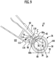
- the cleaning roller 36 comprises (see for example Figure 9 ) a hollow roller 54 with an interior 56. On the hollow roller 54 there is a trimming 58, in particular made of a textile material.
- the cleaning roller 36 is moistened internally.
- Cleaning fluid is supplied to the interior 56 of the hollow roller 44 via line 53.
- the hollow roller 54 is provided with corresponding openings leading to the facing 58. This allows cleaning fluid to escape and moisten the facing 58, which in turn can be applied to the floor 50.
- the cleaning roller 52 can be placed and, in particular, slid onto a rotating shaft mounted on the support device 12 via the hollow roller 54 with the interior space 56.
- the cleaning roller 36 can be fixed to this shaft in a rotationally fixed manner.
- the suction channel device 42 comprises at least one suction channel 60 (cf. Figure 9 ). This suction channel 60 is arranged in the suction channel device 42 and leads from the cleaning roller 36 to the blower device 40.
- blower device 40 with drive 44 is fixedly mounted on the support device 12 and in particular on the first frame rod 16.
- a drive 62 for the cleaning roller 36 is fixedly attached to the second articulated rod 18.
- a gear for transmitting torque to the shaft for the cleaning roller 36 is arranged in the second articulated rod 18.
- a pipe 64 leads from a connection 66 on the suction duct device 42 to a corresponding connection of the blower device 40.
- Pipe bends 68a and 68b are located on the pipe 64.
- the pipe 64 and the pipe bends 68a, 68b are arranged outside the suction duct device 42 and the blower device 40. They are arranged, for example, on a side opposite the drive 62.
- the suction channel device 42 is designed as a housing 70.
- the at least one suction channel 60 can be arranged in a protected manner within this housing 70.
- the dirty liquid container 48 and the separator device 46 can be positioned in a protected manner within the housing.
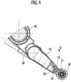
- the suction channel 60 has an opening 72 (see, for example, the Figures 4 and 9 ), which is open towards the cleaning roller 36. Via this mouth 72, the cleaning roller 36 is vacuumed on an outer side, and the suction flow is coupled into the suction channel 60 and thus into the suction channel device 42.
- the mouth 72 comprises a first mouth wall 74 and a second mouth wall 76.
- a mouth opening 78 is formed between the first mouth wall 74 and the second mouth wall 76.
- the first mouth wall 74 is an upper mouth wall with respect to the second mouth wall 76.
- first mouth wall 74 and the second mouth wall 76 there are spaced transverse walls 75a, 75b.
- the first mouth wall 74 has a front side 80a.
- the second mouth wall has a front side 80b (cf. Figure 9 ).
- the end faces 80a and 80b are at least approximately straight and parallel to each other. In particular, the end faces 80a and 80b are parallel to the rotation axis 38.
- the mouth opening 78 is arranged in a fourth quadrant 82 with respect to the cleaning roller 36 when the floor cleaning machine 10 is placed on the floor 50 in an operative mode and is supported by the cleaning roller 36, and a coordinate system is accordingly defined which has axes parallel and perpendicular to the floor 50 and in which the center point runs through the point of intersection of the rotation axis 38.
- the first mouth wall 74 rests against the facing 58 of the cleaning roller 36 or projects into it.
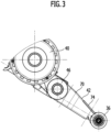
- Figures 3 and 9 an embodiment is shown in which the first mouth wall 74 projects into the trim 58.
- the end face 80a of the first mouth wall 74 lies on the trim 58 or is immersed in the trim 58 ( Figures 4 and 9 ).
- the second mouth wall 76 rests against the facing 58; the end face 80b touches the facing 58 without protruding into it.
- the mouth opening 78 it is also fundamentally possible for the mouth opening 78 to be set back relative to the end face 80b relative to the cleaning roller 36 with the facing 58, i.e., the end face 80b is spaced from the facing 58 or protrudes into the facing 58.
- the suction channel 60 leads from the mouth 72 to the connection 66.
- a contact element 200 is arranged at the mouth 72. In one embodiment, this contact element 200 is arranged on the first mouth wall 74, whereby a fluid seal is established between the first mouth wall 74 and the contact element 200. The contact element 200 points transversely away from the first mouth wall 74.
- the contact element 200 projects into the facing 58 of the cleaning roller 36. It dips into the facing 58 with a lower region.
- the immersion area is a sub-area of the system element 200.
- a contour 202 of the contact element 200 is adapted to the cleaning roller 36.
- the contour 202 facing the cleaning roller 36 is curved with the same curvature as the cleaning roller 36.
- the contact element 200 ensures improved fluid coupling into the orifice 72.
- a contact element 204 is provided, which is seated on the first mouth wall 74 and projects transversely therefrom.
- This contact element 204 has a first end 206, which is spaced apart from the first mouth wall 74. It also has a second end 208, which lies on the mouth 72 and thus on the mouth wall 74.
- the contact element 204 extends between the first end 206 and the second end 208.
- the contact element 204 is not uniformly high (in cross-section) between the first end 206 and the second end 208. It has a first region 210, at which the first end 206 lies. This first region 210 merges into a second region 212 and, in particular, is continuous. over, with the second end 208 located in the second region 212.
- a bottom side 214 of the contact element 204 has a greater distance from the rotational axis 38 of the cleaning roller 36 in the first region 210 than in the second region 212.
- a negative pressure is present at the contact element 200 or 204. Due to the design with the first region 210 and the second region 212, the negative pressure in the region of the first end 206 is reduced compared to the negative pressure in the region of the second end 208. This improves the suction effect, since, in particular, the risk of a fluid short circuit (the drawing out of fluid in the region of the first end 206) is reduced.
- the contact element 200 or the contact element 204 have a length (between the first end 206 and the second end 208) which is greater than a corresponding opening length of the mouth 72.
- a contact element 216 is arranged on the first mouth wall 74. This is completely immersed in the trim 58 of the cleaning roller 36.
- This contact element 216 has a first region 220 at a first end 218 and a second end 222 at the first mouth wall 74, which is formed in a second region 224. In the first region 220, the contact element 216, facing the cleaning roller 36, is at a greater distance from the rotation axis 38 than in the second region 224.
- both the first region 220 and the second region 224 are completely immersed in the trim 58.
- the suction channel 60 tapers in a region toward the separator device 46. This forms a type of funnel 83 on the separator device 46, in order to, on the one hand, achieve effective suction over the entire length of the cleaning roller 36 and, on the other hand, to increase the flow velocity for entry into the separator device.
- the cleaning roller 36 is driven in rotation with a rotation direction 84.
- the rotation of the cleaning roller 36 and the operation of the blower device 40 are simultaneously switched via the switch 34.
- the corresponding drive 62 for the rotation of the cleaning roller 36 and the drive 44 receive their drive energy, for example, from a rechargeable battery device, which is arranged, for example, in the housing 70 of the suction channel device 42 (not shown in the figures), or from mains power.
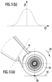
- the direction of rotation 84 is such that a contact line 86 ( Figure 5(a) ) of the cleaning roller 36 on the floor 50 rotates away from the floor 50 toward the mouth 72.
- the direction of rotation 84 is such that, with respect to this, the second mouth wall 76 lies in front of the first mouth wall 74.
- the direction of rotation 84, when the cleaning roller 36 is placed on the floor 50 during proper operation, is a clockwise rotation for a user who is standing on the floor 50.
- the direction of rotation is opposite to the direction of rotation 84, i.e., the rotation is counterclockwise.
- the second mouth wall 76 abuts the facing 58 or protrudes into it.
- the first mouth wall 74 can then abut the facing 58, be spaced apart from it, or protrude into it.
- dirt is picked up, the cleaning roller 36 then rotates from the second quadrant into the first quadrant and from there into the fourth quadrant, and suction takes place at the mouth 72.
- the rotation speed of the cleaning roller 36 is preferably in the range between approximately 200 and 400 revolutions per minute.
- the contact pressure on the cleaning roller 36 is, for example, in the order of approximately 6 kg.
- FIG 5(b) The diagram shows the pressure force curve for a cleaning roller 36 with textile trim 58 as a function of a rotational position.
- the angle of rotation 0 refers to the line 86, as shown in Figure 5(a) is shown.
- the suction channel device 42 with the mouth 72 is connected via an elastic device 90 ( Figure 6 ) is pressed against the cleaning roller 36 and is thus kept pre-tensioned.
- Figure 6 This is shown schematically.
- the elastic device 90 is supported on the carrier device 12 via a first side 92 and on the separator device 46 via a second side 94.
- the separator device 46 and the suction channel device 42 form a unit.
- the separator device 46 and the suction channel device 42 are directly connected to one another.
- the suction channel device 42 supported on the carrier device 12 by the elastic device 90, is pressed against the cleaning roller 36.
- the elastic device 90 is formed by a spring device, for example, with one or more spiral springs or spiral springs.
- the corresponding elastic device 90 is supported on the blower device 40.
- the separator device 46 and the suction duct device 42 are separate.
- the elastic device 90 with one or more springs, is supported on the blower device 40 via the first side 92. It is supported on the separator device 46 via the second side 94 and presses it towards the cleaning roller 36 via a corresponding preload.
- the separator device 46 and the suction duct device 42 are connected to one another; however, the connection is not direct, but rather a frictional connection. The separator device 46 therefore acts with a corresponding contact force on the suction duct device 42 and presses it against the cleaning roller 36.
- the elastic device 90 is supported via the first side 92 on the carrier device 12 (or the blower device 40 or the separator device 46) and via the second side 94 it is supported directly on the suction channel device 42 and presses this directly against the cleaning roller 36 in order to generate the corresponding pretension.
- the cleaning roller 36 is assigned (at least) one sweeping lip 96.
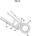
- the sweeping lip 96 is seated in a receptacle 98 ( Figures 9 and 10 (The sweeping lip is not shown in these figures).
- the floor cleaning machine 10 has a front end 100 on the cleaning roller 36.
- the sweeping lip 96 is arranged behind the cleaning roller 36 relative to this front end 100. It is fixed to an underside of the suction duct device 42.
- the sweeping lip 96 closes off a space 102 between a bottom side 104 of the suction channel device 42, which is opposite the first mouth wall 74, and the cleaning roller 36.
- a normal operating mode of the floor cleaning machine 10 is that it is pushed, i.e. pushed forward.
- the corresponding direction is shown in Figure 1 shown by the arrow with reference number 106.
- the sweeping lip 96 is designed such that it rests on the floor 50, thereby sweeping up coarse dirt.
- This coarse dirt in a space 108 between the sweeping lip 96 and the cleaning roller 36 is carried along by the cleaning roller 36 with its direction of rotation 84 and fed to the opening 72, where it can be vacuumed away.
- Coarse dirt can also be vacuumed away through the sweeping lip 96.
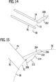
- the sweeping lip 96 is in particular arranged and/or designed to be movable. This is shown in Figure 11 indicated by the arrow with the reference number 110.
- the movable design is, for example, a rubber design with a correspondingly elastic rubber material.
- the sweeping lip 96 can also be arranged in a movable manner, such as pivotably, and in particular can be arranged movably on the suction channel device 42.
- the sweeping lip 96 is then made of a correspondingly hard rubber material.
- the floor cleaning machine 10 has an air supply device 112 (see Figures 9 and 10 ).
- the air supply device 112 provides additional air supply to the cleaning roller 36 at or near the opening 72 in order to enable optimized suction.
- the supply air device comprises (at least) one duct 114, which is arranged in the extraction duct device 42.
- This duct 114 has an inlet opening 116 for coupling in supply air and an outlet opening 118 for coupling out supply air that was coupled in via the inlet opening 116.
- the inlet-side opening 118 is arranged on the underside 104 of the suction channel device 42 at a distance from the cleaning roller 36.
- the outlet-side opening 118 points toward the cleaning roller 36. Relative to the direction of rotation 84, the outlet-side opening 118 is arranged in front of the opening 72.
- the outlet-side orifice 118 is located in particular in the fourth quadrant 82. It is located near the orifice 72.
- the end face 80b of the second mouth wall 76 also forms an end face of a wall in which a mouth opening of the outlet-side mouth 118 is located.
- Supply air can then be coupled in from the room 102 and fed to the cleaning roller 36.
- the supply air device 112 has (at least) one duct 120, which is connected on the inlet side with a corresponding opening (in Figure 10 not shown) is coupled to the blower device 40.
- cooling air or exhaust air from the blower device 40 is used as supply air and then supplied by the blower device 40 through the channel 120 to the cleaning roller 36.
- the channel 120 then runs in particular along the suction channel device 42.
- An outlet-side orifice 118 is basically arranged as described above with reference to the embodiment according to Figure 9 described.
- the cleaning roller 36 is provided with grooves 122.
- a groove is formed in the facing 58.
- a groove 122 is formed, for example, by being a recess in the facing 58, at which no facing is arranged or at which a height of the facing 58 above the hollow roller 54 is lower than outside the corresponding groove 122.
- the groove is shown with a rectangular cross-section.
- the corresponding groove as a recess in the facing 58, can also have a different shape. For example, it can have a circular cross-section or another cross-sectional shape.
- Such a groove 122 then has a space 124.
- the cleaning roller 36 has a plurality of grooves 122 which are spaced apart in an axial direction 126 (which is parallel to the rotation axis 38) and spaced apart in the circumferential direction 128.
- the cleaning roller 36 is structured by the grooves 122.
- the individual grooves 122 are of the suction flow at the orifice 72, a short air pulse is generated. This air pulse can carry away dirt that has become entangled in the bristles 58.
- the grooves 122 are evenly distributed on the cleaning roller 36 with respect to the circumferential direction 128 and the axial direction 126 in order to largely prevent dead zones with regard to the entrainment of contaminants.
- a length of a groove 122 in the axial direction 126 is at most 10% of the length of the cleaning roller 36 with trim 58 in this axial direction 126.
- a width of a groove 122 in the circumferential direction 128 is at most 5% of a total circumference of the cleaning roller 36 on a surface of the facing 58.
- the floor cleaning machine 10 rests only on the cleaning roller 36.
- the floor cleaning machine 10 is designed without support wheels. This prevents abrasion marks caused by support wheels.
- the floor cleaning machine 10 works as follows: During a cleaning process, the floor cleaning machine 10 is operated in such a way that a rotation of the cleaning roller 36 in the direction of rotation 84 is driven by a corresponding drive. The blower device 40 ensures a corresponding negative pressure to provide a suction flow.
- the cleaning roller 36 is moistened from the inside with cleaning fluid from the cleaning fluid container 52, whereby the filling 58 is moistened Suction takes place at the opening 72 through the suction channel device 42 on an outer side of the cleaning roller 36.
- the speed of the cleaning roller 36 is set so that water droplets are largely prevented from being thrown off the cleaning roller 36.
- the direction of rotation 84 is preferably directed toward an operator holding the floor cleaning machine 10 by the user holding unit. This allows for effective normal operation, in which cleaning is carried out from a room to be cleaned.
- the suction channel device 42 with the opening 72 is pressed against the cleaning roller 36 by the elastic device 90 and, in particular, by spring force, so that effective suction occurs.
- the first opening wall 74 rests against the trimming 58 or penetrates it.
- the sweeping lip 96 provides a sweeping function for particles that are not directly picked up by the cleaning roller 36.
- the cleaning roller 36 is a wiping roller.
- the sweeping lip 96 ensures that even coarse dirt reaches the outlet 72 by being carried along by the cleaning roller 36.
- the air supply device 112 ensures a sufficient air supply. Air can then be supplied from the environment, or process exhaust air or blower exhaust air can be supplied. This, in turn, enables good coarse dirt collection with sufficient residual moisture content.
- the cleaning roller 36 rests on the floor 50. At a contact line, the highest contact force prevails and the largest amount of cleaning fluid is provided there, which in turn can soften dirt on the floor 50. The contact force outside this contact line 86 is correspondingly lower, and the cleaning fluid concentration is then also lower. Subsequent drying can then take place on the floor 50 via the cleaning roller 36.
- the entire weight of the device rests on the cleaning roller 36.
- the cleaning roller 36 is structured by the grooves 122. This creates short air pulses as the suction stream passes through the orifice 72, allowing for the removal of contaminants caught on the bristles 58.
- a first embodiment is a floor cleaning machine, in particular a hand-guided and/or hand-held floor cleaning machine, comprising a carrier device (12), at least one cleaning roller (36) which is arranged on the carrier device (12), can be driven in rotation and is provided with a covering (58), a blower device (40) for generating a suction flow, and a suction channel device (42) for the suction flow, which provides at least one suction channel (60) with a fluid-effective connection between the blower device (40) and the at least one cleaning roller (36), wherein the at least one suction channel (60) has at least one opening (72) towards the at least one cleaning roller (36) and the at least one opening (72) has a first opening wall (74) and a spaced-apart second opening wall (76), between which an opening opening (78) is formed, wherein when the at least one cleaning roller (36) is placed on a floor (50) to be cleaned a cleaning roller (36), the first mouth wall (74) is positioned above the second mouth wall (76) with respect
- an end face (80a) of the first mouth wall (74) and/or an end face (80b) of the second mouth wall (76) is at least approximately parallel to a rotation axis (38) of the at least one cleaning roller (36).
- the first mouth wall (74) rests against the trim (58) or projects into it and the second mouth wall (76) rests against the trim (56) of the at least one cleaning roller (36) or is spaced from it or projects into it or the second mouth wall (76) rests against the trim (56) or projects into it and the first mouth wall lies (74) rests against the trim (56), is spaced from it or projects into it.
- a contact element (200; 204; 216) is arranged on the mouth (72), which contact element rests against the trim (58) or projects into it, and which projects transversely away from the first mouth wall (74) or the second mouth wall (76), wherein a fluid seal is present between the contact element (200; 204; 216) and the corresponding mouth wall (74; 76).
- the contact element (200; 204; 216) is located on the first mouth wall (74).
- the contact element (200; 204; 216) facing the at least one cleaning roller (36) has a curved contour which is adapted to the at least one cleaning roller (36).
- the contact element (204; 216) has a first end (206; 218) which is spaced from the mouth (72) and has a second end (208; 222) which is positioned at the mouth (72), and the contact element (204; 216) is designed such that a resulting negative pressure at the first end (206; 218) is smaller than at the second end (208; 222).
- the contact element (204; 216) has a first region (210; 220) with the first end (206; 218) and a second region (212; 224) with the second end (208; 222), wherein a distance of the contact element (204; 216) at the first region (210; 220) to a rotation axis (38) of the at least one cleaning roller (36) is greater than at the second region (212; 224).
- the second mouth wall (76) is arranged in front of the first mouth wall (74) with respect to a direction of rotation (84) of the at least one cleaning roller (36).
- a distance between an end face (80a) of the first mouth wall (74) and a rotation axis (84) of the at least one cleaning roller (36) is smaller than a distance between an end face (80b) of the second mouth wall (76) and the rotation axis (84).
- the mouth opening (78) of the at least one mouth (72) has at least approximately a rectangular cross-section.
- the at least one suction channel (60) is designed to taper in cross section towards a separator device (46).
- At least one cleaning liquid container (52) is provided, which is in fluid connection with the at least one cleaning roller (36), wherein cleaning liquid is provided on the at least one cleaning roller (36), in particular via an interior space (56) of the at least one cleaning roller (36).
- the at least one cleaning liquid container (52) is arranged on a user holding unit.
- the blower device (40) is arranged on the carrier device (12) and/or the suction channel device (42) is arranged on the carrier device (12).
- the suction channel device (42) comprises a housing (70) in which the at least one suction channel (60) is arranged or formed.
- an elastic device (90) is provided, by means of which the suction channel device (42) is elastically pressed against the at least one cleaning roller (36), wherein the elastic device (90) is or comprises in particular a spring device.
- the elastic device (90) is supported on the carrier device (12) via a first side (92).
- the elastic device (90) is supported via a first side (12) on the blower device (40) or a separator device (46).
- the elastic device (90) is supported on the suction channel device (42) via a second side (94).
- the elastic device (90) is supported via a second side (94) on the blower device (40) or separator device (46), wherein the blower device (40) is connected to the suction duct device (42) or separator device (46), wherein the connection is a direct connection or a frictional connection.
- a dirty liquid container (48) is provided which is associated with a separator device (46).
- the dirty liquid container (48) is arranged on the suction channel device (42).
- a user holding unit is arranged on the support device (12), which is pivotably arranged in particular on a joint (22).
- a pivot axis (26) of the joint (22) is oriented parallel to a rotation axis (38) of the at least one cleaning roller (36).
- the user holding unit comprises a rod device (24) on which a handle (28) is seated.
- the floor cleaning machine during a cleaning process the floor cleaning machine is supported on the floor (50) only via the at least one cleaning roller (36) and in particular a design without support wheels is provided.
- a direction of rotation (84) of the at least one cleaning roller (36) is from a line of contact (86) with the floor (50) to be cleaned towards the second mouth wall (76) and then towards the first mouth wall (74) and in particular the direction of rotation (84) is clockwise when the at least one cleaning roller (36) is placed on the floor (50).
- the at least one cleaning roller (36) is provided with grooves (122) for generating air pulses in a suction flow.
- a groove (122) is formed by a litter-free or litter-reduced area.
- a plurality of spaced grooves (122) are provided which are spaced apart in an axial direction (126) of the at least one cleaning roller (36) and in a circumferential direction (128) of the at least one cleaning roller (36).
- a groove (122) has a length which is at most 10% of an axial length of the at least one cleaning roller (36).
- a groove (122) has a width which is at most 5% of a circumferential length of the at least one cleaning roller (36).
- At least one sweeping lip (96) is arranged on the suction channel device (42).
- the at least one sweeping lip (96) is arranged and designed such that coarse dirt between the at least one sweeping lip (96) and the at least one cleaning roller (36) is entrained by the at least one cleaning roller (36) and fed to the at least one opening (72).
- the at least one sweeping lip (96) separates a space (102) behind the at least one cleaning roller (36) and below the suction channel device (42) towards the floor (50) to be cleaned from the at least one cleaning roller (36) when the at least one cleaning roller (36) is placed on the floor (50).
- the at least one sweeping lip (96) is arranged and/or designed to be movable and, in particular, is designed to be elastic.
- an air supply device (112) is provided, by means of which air supply is provided to the at least one cleaning roller (36).
- the supply air device has at least one duct (114; 120) with at least one outlet-side opening (118) for supply air, which is aligned towards the at least one cleaning roller (36), wherein in particular the at least one duct (114; 120) for supply air is arranged or formed on the suction duct device (42).
- the at least one outlet-side opening (118) for supply air is arranged between the at least one opening (72) for the suction flow and the at least one sweeping lip (96).
- the at least one channel (114; 120) has at least one inlet-side opening (116) for supply air, via which supply air can be coupled in.
- the at least one inlet-side opening (116) is arranged on an underside (104) of the suction channel device (42) and is arranged in particular on or near an end of the suction channel device (42) associated with the at least one cleaning roller (36).
- the at least one channel (120) is guided along the suction channel device (42).
- the at least one channel (120) is led to the blower device (40).
Landscapes
- Engineering & Computer Science (AREA)
- Mechanical Engineering (AREA)
- Cleaning In General (AREA)
- Nozzles For Electric Vacuum Cleaners (AREA)
Priority Applications (1)
| Application Number | Priority Date | Filing Date | Title |
|---|---|---|---|
| EP25168801.6A EP4555910A3 (fr) | 2013-12-12 | 2013-12-12 | Machine de nettoyage du sol |
Applications Claiming Priority (5)
| Application Number | Priority Date | Filing Date | Title |
|---|---|---|---|
| PCT/EP2013/076445 WO2015086083A1 (fr) | 2013-12-12 | 2013-12-12 | Machine de nettoyage des sols |
| EP23150816.9A EP4193898B1 (fr) | 2013-12-12 | 2013-12-12 | Machine de nettoyage du sol dotée d'un dispositif séparateur |
| EP13811154.7A EP3079553B1 (fr) | 2013-12-12 | 2013-12-12 | Machine de nettoyage des sols |
| EP20200459.4A EP3795055B1 (fr) | 2013-12-12 | 2013-12-12 | Machine de nettoyage des sols |
| EP25168801.6A EP4555910A3 (fr) | 2013-12-12 | 2013-12-12 | Machine de nettoyage du sol |
Related Parent Applications (3)
| Application Number | Title | Priority Date | Filing Date |
|---|---|---|---|
| EP13811154.7A Division EP3079553B1 (fr) | 2013-12-12 | 2013-12-12 | Machine de nettoyage des sols |
| EP20200459.4A Division EP3795055B1 (fr) | 2013-12-12 | 2013-12-12 | Machine de nettoyage des sols |
| EP23150816.9A Division EP4193898B1 (fr) | 2013-12-12 | 2013-12-12 | Machine de nettoyage du sol dotée d'un dispositif séparateur |
Publications (3)
| Publication Number | Publication Date |
|---|---|
| EP4555910A2 true EP4555910A2 (fr) | 2025-05-21 |
| EP4555910A8 EP4555910A8 (fr) | 2025-07-09 |
| EP4555910A3 EP4555910A3 (fr) | 2025-09-03 |
Family
ID=49841645
Family Applications (7)
| Application Number | Title | Priority Date | Filing Date |
|---|---|---|---|
| EP23150893.8A Active EP4193899B1 (fr) | 2013-12-12 | 2013-12-12 | Machine de nettoyage de sol avec lèvre de balayage |
| EP20200459.4A Active EP3795055B1 (fr) | 2013-12-12 | 2013-12-12 | Machine de nettoyage des sols |
| EP23150816.9A Active EP4193898B1 (fr) | 2013-12-12 | 2013-12-12 | Machine de nettoyage du sol dotée d'un dispositif séparateur |
| EP23150332.7A Active EP4190219B1 (fr) | 2013-12-12 | 2013-12-12 | Machine de nettoyage de sol |
| EP25168801.6A Pending EP4555910A3 (fr) | 2013-12-12 | 2013-12-12 | Machine de nettoyage du sol |
| EP13811154.7A Active EP3079553B1 (fr) | 2013-12-12 | 2013-12-12 | Machine de nettoyage des sols |
| EP23150701.3A Active EP4186406B1 (fr) | 2013-12-12 | 2013-12-12 | Machine de nettoyage de sol avec dispositif à barre |
Family Applications Before (4)
| Application Number | Title | Priority Date | Filing Date |
|---|---|---|---|
| EP23150893.8A Active EP4193899B1 (fr) | 2013-12-12 | 2013-12-12 | Machine de nettoyage de sol avec lèvre de balayage |
| EP20200459.4A Active EP3795055B1 (fr) | 2013-12-12 | 2013-12-12 | Machine de nettoyage des sols |
| EP23150816.9A Active EP4193898B1 (fr) | 2013-12-12 | 2013-12-12 | Machine de nettoyage du sol dotée d'un dispositif séparateur |
| EP23150332.7A Active EP4190219B1 (fr) | 2013-12-12 | 2013-12-12 | Machine de nettoyage de sol |
Family Applications After (2)
| Application Number | Title | Priority Date | Filing Date |
|---|---|---|---|
| EP13811154.7A Active EP3079553B1 (fr) | 2013-12-12 | 2013-12-12 | Machine de nettoyage des sols |
| EP23150701.3A Active EP4186406B1 (fr) | 2013-12-12 | 2013-12-12 | Machine de nettoyage de sol avec dispositif à barre |
Country Status (7)
| Country | Link |
|---|---|
| US (6) | US9999332B2 (fr) |
| EP (7) | EP4193899B1 (fr) |
| CN (2) | CN105873489B (fr) |
| DE (2) | DE202013012694U1 (fr) |
| PL (5) | PL4186406T3 (fr) |
| RU (1) | RU2671396C1 (fr) |
| WO (1) | WO2015086083A1 (fr) |
Families Citing this family (64)
| Publication number | Priority date | Publication date | Assignee | Title |
|---|---|---|---|---|
| EP4193899B1 (fr) | 2013-12-12 | 2024-12-04 | Alfred Kärcher SE & Co. KG | Machine de nettoyage de sol avec lèvre de balayage |
| DE102014114809A1 (de) | 2014-10-13 | 2016-04-14 | Alfred Kärcher Gmbh & Co. Kg | Flächen-Reinigungsmaschine mit Befeuchtungseinrichtung |
| DE102014114776A1 (de) * | 2014-10-13 | 2016-04-14 | Alfred Kärcher Gmbh & Co. Kg | Flächen-Reinigungsmaschine |
| DE102014114813A1 (de) | 2014-10-13 | 2016-04-14 | Alfred Kärcher Gmbh & Co. Kg | Flächen-Reinigungsmaschine und Verfahren zum Betreiben einer Flächen-Reinigungsmaschine |
| UA118498C2 (uk) | 2014-10-13 | 2019-01-25 | Альфред Керхер Гмбх Унд Ко. Кг | Машина для чистки поверхонь |
| WO2017063663A1 (fr) | 2015-10-12 | 2017-04-20 | Alfred Kärcher Gmbh & Co. Kg | Machine de nettoyage de surfaces |
| PL3426122T3 (pl) * | 2016-03-09 | 2021-12-13 | Alfred Kärcher SE & Co. KG | Maszyna do czyszczenia powierzchni |
| PL3426121T3 (pl) | 2016-03-09 | 2021-11-08 | Alfred Kärcher SE & Co. KG | Maszyna do czyszczenia powierzchni |
| PL3592193T3 (pl) * | 2017-03-08 | 2021-09-06 | Alfred Kärcher SE & Co. KG | Samojezdne i samokierujące urządzenie do czyszczenia podłogi |
| RU2733363C1 (ru) | 2017-08-11 | 2020-10-01 | Альфред Керхер Се Унд Ко. Кг | Машина для чистки поверхностей с закрывающим устройством для устройства для сбора грязной жидкости |
| DE102017120723A1 (de) | 2017-09-08 | 2019-03-14 | Alfred Kärcher SE & Co. KG | Reinigungsmaschinen-Station für eine Reinigungsmaschine, Reinigungsmaschine und Kombination aus Reinigungsmaschinen-Station und Reinigungsmaschine |
| DE102017120722A1 (de) | 2017-09-08 | 2019-03-14 | Alfred Kärcher SE & Co. KG | Flächen-Reinigungsmaschine mit gegenläufigen Reinigungswalzeneinheiten und Verfahren zum Betreiben einer Flächen-Reinigungsmaschine |
| US10702116B2 (en) | 2017-09-15 | 2020-07-07 | Omachron Intellectual Property Inc. | Surface cleaning apparatus |
| DE102018101646A1 (de) | 2018-01-25 | 2019-07-25 | Alfred Kärcher SE & Co. KG | Reinigungswalze und Boden-Reinigungsmaschine |
| JP2020509791A (ja) * | 2018-02-13 | 2020-04-02 | 深▲セン▼市赫▲ジ▼科技有限公司HIZERO Technologies Co.,Ltd. | ローラ清掃装置及び清掃ロボット |
| AU2019288675B2 (en) | 2018-06-22 | 2022-03-24 | Bissell Inc. | Surface cleaning apparatus and tray |
| US11291345B2 (en) | 2018-08-27 | 2022-04-05 | Techtronic Floor Care Technology Limited | Floor cleaner |
| EP3897330B1 (fr) | 2018-12-21 | 2023-09-06 | Tennant Company | Système de balai/laveuse capable de traiter de gros débris |
| US11304581B2 (en) | 2019-01-08 | 2022-04-19 | Bissell Inc. | Surface cleaning apparatus |
| CN109700392B (zh) * | 2019-01-31 | 2021-08-06 | 无锡睿米信息技术有限公司 | 一种智能拖地机器人 |
| DE102019103651A1 (de) | 2019-02-13 | 2020-08-13 | Alfred Kärcher SE & Co. KG | Bodendüse für ein Reinigungsgerät mit Saugfunktion, Reinigungsgerät und Verfahren zum Absaugen eines Bodenbereichs |
| EP3952710B1 (fr) | 2019-04-08 | 2025-08-06 | Alfred Kärcher SE & Co. KG | Machine de nettoyage de surfaces dotée d'un réservoir pour nettoyant liquide et d'un dispositif de détection et procédé pour faire fonctionner une machine de nettoyage de surfaces |
| CN113645888B (zh) | 2019-04-08 | 2023-06-20 | 阿尔弗雷德·卡赫欧洲两合公司 | 具有脏污流体罐装置的面清洁机 |
| DE102019109298A1 (de) * | 2019-04-09 | 2020-10-15 | Alfred Kärcher SE & Co. KG | Reinigungsmaschinen-Station für eine Reinigungsmaschine, Reinigungsmaschine, Kombination aus Reinigungsmaschinen-Station und Reinigungsmaschine und Verfahren |
| WO2020207603A1 (fr) | 2019-04-12 | 2020-10-15 | Alfred Kärcher SE & Co. KG | Machine de nettoyage de surfaces à mode de suralimentation et procédé pour faire fonctionner une machine de nettoyage de surfaces |
| DE102019109946A1 (de) | 2019-04-15 | 2020-10-15 | Alfred Kärcher SE & Co. KG | Reinigungsmaschine mit Gelenkeinrichtung und Reinigungsmaschine mit Antriebseinrichtung |
| CN110151076A (zh) * | 2019-05-23 | 2019-08-23 | 中山市金舜家庭用品有限公司 | 一种清洁辊及滚动蒸汽地拖 |
| DE102019119211A1 (de) * | 2019-07-16 | 2021-01-21 | Alfred Kärcher SE & Co. KG | Reinigungsmaschine und Verfahren zum Betreiben einer Reinigungsmaschine |
| WO2021013343A1 (fr) | 2019-07-24 | 2021-01-28 | Alfred Kärcher SE & Co. KG | Machine de nettoyage de sols |
| EP4025110A1 (fr) | 2019-09-06 | 2022-07-13 | Alfred Kärcher SE & Co. KG | Nettoyeur du sol avec ramassage des cheveux et procédé de fonctionnement d'un nettoyeur de sol |
| AU2020260510B2 (en) | 2019-11-06 | 2022-03-31 | Bissell Inc. | Surface cleaning apparatus |
| EP3892179A1 (fr) | 2020-04-06 | 2021-10-13 | Koninklijke Philips N.V. | Dispositif de nettoyage et buse d'aspirateur conçue pour être utilisée dans un dispositif de nettoyage |
| US12042107B2 (en) | 2021-03-04 | 2024-07-23 | Bissell Inc. | Surface cleaning apparatus |
| US11122946B2 (en) | 2021-03-04 | 2021-09-21 | Bissell Inc. | Brushroll for surface cleaning apparatus |
| US11160431B2 (en) | 2021-03-04 | 2021-11-02 | Bissell Inc. | Surface cleaning apparatus |
| US12035873B2 (en) | 2021-08-31 | 2024-07-16 | Bissell Inc. | Surface cleaning apparatus |
| DE202021002931U1 (de) | 2021-09-11 | 2021-10-01 | Matthias Jünemann | Equilateraler Flächenreiniger |
| DE102021134463A1 (de) | 2021-12-23 | 2023-07-13 | Alfred Kärcher SE & Co. KG | Flächenreinigungsmaschine mit gekrümmtem Abstreifelement |
| DE102021134612A1 (de) | 2021-12-23 | 2023-06-29 | Alfred Kärcher SE & Co. KG | Bodenreinigungsmaschine mit mindestens einem Abstützelement |
| DE102021134552A1 (de) | 2021-12-23 | 2023-06-29 | Alfred Kärcher SE & Co. KG | Bodenreinigungsmaschine mit Schwenkgelenk und Verfahren zum Betreiben einer Bodenreinigungsmaschine |
| DE102021134577A1 (de) | 2021-12-23 | 2023-06-29 | Alfred Kärcher SE & Co. KG | Bodenreinigungsmaschine mit Trittlasche und Verfahren zur Abnahme einer Schmutzfluidtankeinrichtung von einem Reinigungskopf |
| AU2022291569A1 (en) | 2022-01-10 | 2023-07-27 | Bissell Inc. | Surface cleaning apparatus with steam |
| US11986139B2 (en) | 2022-02-02 | 2024-05-21 | Bissell Inc. | Extraction cleaner with steam |
| DE202022101314U1 (de) | 2022-02-08 | 2022-06-20 | Alfred Kärcher SE & Co. KG | Bodenreinigungsgerät mit Schmutzfluid-Tank |
| DE102022102937A1 (de) | 2022-02-08 | 2023-08-10 | Alfred Kärcher SE & Co. KG | Bodenreinigungsgerät mit Schmutzfluid-Tank |
| DE102022102918A1 (de) | 2022-02-08 | 2023-08-10 | Alfred Kärcher SE & Co. KG | Bodenreinigungsgerät mit Kassette |
| DE202022101313U1 (de) | 2022-02-08 | 2022-06-20 | Alfred Kärcher SE & Co. KG | Bodenreinigungsgerät mit beweglichem Abstreifelement |
| EP4475728A1 (fr) | 2022-02-08 | 2024-12-18 | Alfred Kärcher SE & Co. KG | Dispositif de nettoyage de plancher avec dispositif de balayage et procédé de fonctionnement d'un dispositif de nettoyage de plancher |
| WO2023152163A1 (fr) | 2022-02-08 | 2023-08-17 | Alfred Kärcher SE & Co. KG | Dispositif de nettoyage de plancher avec unité de palier pivotant à butée |
| DE102022133009A1 (de) | 2022-02-08 | 2023-08-10 | Alfred Kärcher SE & Co. KG | Bodenreinigungsgerät mit Drehlagereinrichtung mit Widerlager |
| DE202022101312U1 (de) | 2022-02-08 | 2022-06-20 | Alfred Kärcher SE & Co. KG | Bodenreinigungsgerät mit Kassette |
| DE102022102924A1 (de) | 2022-02-08 | 2023-08-10 | Alfred Kärcher SE & Co. KG | Bodenreinigungsgerät mit beweglichem Abstreifelement |
| CN116671822A (zh) * | 2022-02-22 | 2023-09-01 | 苏州爱普电器有限公司 | 一种表面清洁装置 |
| CN114515126B (zh) * | 2022-02-24 | 2025-07-29 | 珠海格力电器股份有限公司 | 地刷组件及清洁设备 |
| DE102022124120A1 (de) | 2022-09-20 | 2024-03-21 | Alfred Kärcher SE & Co. KG | Bodenreinigungsgerät mit Becken und Verfahren zum Betreiben eines Bodenreinigungsgeräts |
| DE102022133004A1 (de) | 2022-12-12 | 2024-06-13 | Alfred Kärcher SE & Co. KG | Bodenreinigungsgerät mit Bodenkopf mit Wandung |
| DE102022133006A1 (de) | 2022-12-12 | 2024-06-13 | Alfred Kärcher SE & Co. KG | Bodenreinigungsgerät mit Schmutzfluid-Tank mit zwei Bereichen |
| EP4665193A1 (fr) | 2023-02-16 | 2025-12-24 | Alfred Kärcher SE & Co. KG | Machine de nettoyage de planchers avec module de base et module de nettoyage |
| DE102023104615A1 (de) | 2023-02-24 | 2024-08-29 | Alfred Kärcher SE & Co. KG | Flächenreinigungsmaschine mit Heißfluiderzeugungseinrichtung und Verfahren zum Betreiben einer Flächenreinigungsmaschine |
| EP4716491A1 (fr) | 2023-05-23 | 2026-04-01 | SharkNinja Operating LLC | Appareil de nettoyage |
| IT202300013158A1 (it) * | 2023-06-26 | 2024-12-26 | Duplex Ind S R L | Macchina per la pulizia e il lavaggio di pavimenti |
| DE102023118815A1 (de) | 2023-07-17 | 2025-01-23 | Alfred Kärcher SE & Co. KG | Abscheider-Behälter-Vorrichtung für eine Reinigungsmaschine, Reinigungsmaschine und Verfahren zum Betreiben einer Abscheider-Behälter-Vorrichtung |
| USD1105672S1 (en) | 2023-08-30 | 2025-12-09 | Sharkninja Operating Llc | Vacuum cleaner and vacuum nozzle |
| USD1113019S1 (en) | 2024-05-31 | 2026-02-10 | Sharkninja Operating Llc | Steam cleaner |
Citations (6)
| Publication number | Priority date | Publication date | Assignee | Title |
|---|---|---|---|---|
| CH607578A5 (en) | 1976-02-25 | 1978-09-15 | Peter Amhof | Brush device, in particular for cleaning gratings |
| DE4117957A1 (de) | 1991-05-31 | 1992-12-03 | Bernd Krallmann | Verfahren und vorrichtung zum saeubern bzw. reinigen einer flaeche, insbesondere einer fussbodenflaeche |
| FR2797895A1 (fr) | 1999-09-01 | 2001-03-02 | Mathieu Yno S A | Brosse cylindrique autolavante pour balayeuses ou autres vehicules |
| US20020194692A1 (en) | 2001-06-20 | 2002-12-26 | Giddings Daniel G. | Apparatus and method for cleaning fabrics, floor coverings, and bare floor surfaces utilizing a soil transfer cleaning medium |
| EP2177128A1 (fr) | 2008-10-16 | 2010-04-21 | Koninklijke Philips Electronics N.V. | Ensemble de brosse de distribution de fluides et son procédé de fonctionnement |
| WO2010140967A1 (fr) | 2009-06-03 | 2010-12-09 | Leif Yxfeldt | Procédé et dispositif de traitement de surfaces |
Family Cites Families (163)
| Publication number | Priority date | Publication date | Assignee | Title |
|---|---|---|---|---|
| DE294642C (fr) | ||||
| US1436420A (en) | 1920-11-22 | 1922-11-21 | Edward E Stout | Burner top |
| US1625147A (en) | 1924-11-21 | 1927-04-19 | Onofrio Anastas | Combined scrubbing and vacuum-cleaning device |
| US1759881A (en) | 1926-04-26 | 1930-05-27 | Bentley Garfield | Floor scrubbing and drying device |
| AT270930B (de) | 1964-11-05 | 1969-05-12 | Reima Reinigungsmaschinen Gmbh | Vorrichtung zur Reinigung von textilen Bodenbelägen, wie Teppichen od.dgl. |
| CH439619A (de) | 1966-10-13 | 1967-07-15 | Walther Buerstenfab | Teppich- und Bodenreinigungsgerät |
| US4136420A (en) | 1977-04-15 | 1979-01-30 | Chemko Industries, Inc. | Carpet soil extracting wand having a powered brush |
| US4173054A (en) | 1977-08-11 | 1979-11-06 | Hukuba Kogyo Kabushiki Kaisha | Floor sweeper |
| US4168723A (en) | 1977-11-18 | 1979-09-25 | Chicago Pneumatic Tool Company | Pressure relief valve |
| DE2963036D1 (en) | 1978-12-19 | 1982-07-22 | Vax Appliances Ltd | Apparatus for cleaning floors, carpets and the like |
| US4266317A (en) | 1979-05-18 | 1981-05-12 | John Duda | Vacuum cleaning apparatus |
| SE432352B (sv) | 1983-05-24 | 1984-04-02 | Postonen Arne Johannes | Maskin for rengoring av foretredesvis harda underlag |
| US4573235A (en) | 1984-10-26 | 1986-03-04 | The Scott & Fetzer Company | Rug cleaning attachment |
| DE3541370A1 (de) | 1984-11-23 | 1986-05-28 | Domnick Hunter Filters Ltd., Birtley, Co. Durham | Fluessigkeits/gas-abscheider |
| DE8437619U1 (de) | 1984-12-21 | 1986-04-17 | Siemens AG, 1000 Berlin und 8000 München | Mit Laufrädern versehenes Bürstsaugmundstück |
| US4728942A (en) | 1985-12-09 | 1988-03-01 | The Scott & Fetzer Company | Self-powered rotation indicator |
| DK172087A (da) | 1987-04-03 | 1988-10-04 | Rotowash Scandinavia | Apparat til vaadrensning af gulv- eller vaegflader |
| US4864682A (en) | 1988-05-02 | 1989-09-12 | Whirlpool Corporation | Self-adjusting wiper strip assembly for a vacuum cleaner |
| JPH0223976A (ja) * | 1988-07-13 | 1990-01-26 | Eishin Giken:Kk | ボーリングレーンメンテナンス装置におけるクリーニング・ローラ |
| US4875246A (en) | 1988-07-22 | 1989-10-24 | Quad Research, Inc. | Surface treating device |
| US4959628A (en) * | 1988-07-22 | 1990-09-25 | Quad Research, Inc. | Rotating electric switch actuated by fixed magnetic means, usable for a surface cleaning device |
| NO168804C (no) | 1989-05-29 | 1992-04-08 | Terje Gjerde | Vaskemaskin |
| ATE101792T1 (de) | 1989-12-01 | 1994-03-15 | William Hendrick Williams | Nass- und trockensauger. |
| US5086539A (en) * | 1990-10-31 | 1992-02-11 | Racine Industries, Inc. | Carpet cleaning machine with pattern-oriented vacuum nozzle |
| JPH0687836B2 (ja) | 1991-11-14 | 1994-11-09 | 三星電子株式会社 | 湿乾式真空掃除機 |
| CN2109165U (zh) | 1991-12-16 | 1992-07-08 | 姜和信 | 一种扫地装置 |
| US5350432A (en) | 1992-04-23 | 1994-09-27 | Goldstar Co., Ltd. | Dirt filtering and collecting apparatus for vacuum cleaner |
| US5221828A (en) | 1992-07-16 | 1993-06-22 | General Motors Corporation | Heated wiper blade using conductive elastomer |
| US5287581A (en) | 1992-11-02 | 1994-02-22 | Lo Kam C | Cleaning device having at least one rotating cylindrical sponge |
| CA2123740C (fr) | 1993-05-19 | 2002-12-17 | Hee-Gwon Chae | Aspirateur |
| CN2174947Y (zh) | 1993-09-11 | 1994-08-24 | 苏州春花吸尘器总厂 | 吸尘器地面刷 |
| JP3270248B2 (ja) | 1993-10-22 | 2002-04-02 | シャープ株式会社 | 電気掃除機 |
| US5500977A (en) | 1994-01-14 | 1996-03-26 | The Hoover Company | Upright carpet extractor |
| FI1987U1 (fi) | 1995-01-30 | 1995-07-06 | Sisko Tuulikki Mussalo | Hjaelputrustning vid dammsugare |
| US5657503A (en) | 1995-06-07 | 1997-08-19 | Caruso; Steven Jerome | Automated rotary mopping, waxing, and light sweeping systems |
| GB9516689D0 (en) | 1995-08-15 | 1995-10-18 | Vax Ltd | Liquid pick-upappliances for use insurface cleaning or drying |
| US6041472A (en) | 1995-11-06 | 2000-03-28 | Bissell Homecare, Inc. | Upright water extraction cleaning machine |
| US6167587B1 (en) | 1997-07-09 | 2001-01-02 | Bissell Homecare, Inc. | Upright extraction cleaning machine |
| US5784755A (en) | 1996-01-18 | 1998-07-28 | White Consolidated Industries, Inc. | Wet extractor system |
| US5657504A (en) | 1996-10-03 | 1997-08-19 | Khoury; Fouad M. | Roller mop with wet roller, squeegee, and debris pickup |
| CN2266377Y (zh) | 1996-11-07 | 1997-11-05 | 张少伟 | 一种手推清扫工具 |
| DE19650565C2 (de) | 1996-12-05 | 1999-04-01 | Hako Gmbh & Co | Reinigungsmaschine mit einer Scheuereinheit |
| US6367120B2 (en) | 1997-03-07 | 2002-04-09 | David A. Beauchamp | Carpet cleaning apparatus with loop agitator |
| KR100384980B1 (ko) | 1998-04-03 | 2003-06-02 | 마츠시타 덴끼 산교 가부시키가이샤 | 회전 브러시 장치 및 이를 이용한 전기 기구 |
| GB2341124B (en) | 1998-09-04 | 2003-03-19 | Stimvak Ltd | Suction cleaner |
| US6206058B1 (en) | 1998-11-09 | 2001-03-27 | The Procter & Gamble Company | Integrated vent and fluid transfer fitment |
| US6256833B1 (en) | 1999-01-20 | 2001-07-10 | Bissell Homecare, Inc. | Upright vacuum cleaner with handle-mounted lamp assembly and height adjustment |
| JP2000342495A (ja) | 1999-06-04 | 2000-12-12 | Matsushita Electric Ind Co Ltd | 電気掃除機用吸込具並びに電気掃除機 |
| CN1135098C (zh) | 1999-06-19 | 2004-01-21 | 韩基焕 | 自驱动的自动吸尘器 |
| JP4286984B2 (ja) | 1999-07-29 | 2009-07-01 | クリーン工業株式会社 | 手押し型ローラー刷毛クリーナー |
| WO2001037716A1 (fr) | 1999-11-24 | 2001-05-31 | Hugh Rogers Mclaughlin | Dispositif de nettoyage de sols et d'elimination de liquides |
| IT1310795B1 (it) | 1999-12-10 | 2002-02-22 | Vidoni Mario | Apparecchio di pulizia con spazzola intercambiabile |
| JP2001246216A (ja) | 1999-12-28 | 2001-09-11 | Denso Corp | 気液分離装置 |
| US6499183B1 (en) | 2000-09-29 | 2002-12-31 | Oreck Holdings, Llc | Low-profile and highly-maneuverable vacuum cleaner having a headlight, a sidelight, anti-ingestion bars, side brushes, a squeegee, and a scent cartridge |
| US6571421B1 (en) | 2000-10-03 | 2003-06-03 | John Chun Kuen Sham | Vacuum cleaner and steamer apparatus |
| US6533871B2 (en) | 2001-01-12 | 2003-03-18 | Royal Appliance Mfg. Co. | Carpet extractor with dual nozzles for dual brushrolls |
| DE10110906A1 (de) | 2001-03-07 | 2002-09-19 | Kaercher Gmbh & Co Alfred | Kehrgerät |
| DE10112396A1 (de) | 2001-03-13 | 2002-10-02 | Krupp Uhde Gmbh | Verfahren zur Verringerung des N¶2¶O-Gehalts in Gasen und ausgewählte Katalysatoren |
| US20040172769A1 (en) * | 2001-06-20 | 2004-09-09 | Giddings Daniel G. | Method and apparatus for cleaning fabrics, floor coverings, and bare floor surfaces utilizing a soil transfer cleaning medium |
| GB0225618D0 (en) | 2002-11-02 | 2002-12-11 | Grey Nicholas G | Surface cleaning apparatus |
| DE10242257C5 (de) | 2001-09-14 | 2017-05-11 | Vorwerk & Co. Interholding Gmbh | Selbsttätig verfahrbares Bodenstaub-Aufsammelgerät, sowie Kombination eines derartigen Aufsammelgerätes und einer Basisstation |
| US6832409B2 (en) | 2001-09-18 | 2004-12-21 | The Hoover Company | Wet/dry floor cleaning unit and method of cleaning |
| US6735812B2 (en) * | 2002-02-22 | 2004-05-18 | Tennant Company | Dual mode carpet cleaning apparatus utilizing an extraction device and a soil transfer cleaning medium |
| KR100437114B1 (ko) | 2002-05-29 | 2004-06-23 | 삼성광주전자 주식회사 | 진공청소기용 사이클론 집진장치 및 이를 구비하는진공청소기 |
| JP2004008738A (ja) | 2002-06-05 | 2004-01-15 | Misuo Fujiwara | 内装用素材の洗浄器及び洗浄装置並びに処理液回収器 |
| US7150068B1 (en) | 2002-08-12 | 2006-12-19 | Gary Dean Ragner | Light-weight self-propelled vacuum cleaner |
| US20040134016A1 (en) | 2003-01-10 | 2004-07-15 | Royal Appliance Manufacturing Company | Suction wet jet mop |
| US7137169B2 (en) | 2003-01-10 | 2006-11-21 | Royal Appliance Mfg. Co. | Vacuum cleaner with cleaning pad |
| JP3937405B2 (ja) | 2003-01-22 | 2007-06-27 | 三菱電機株式会社 | 電気掃除機用吸込み具及びこれを備えた電気掃除機 |
| US7022003B1 (en) * | 2003-05-07 | 2006-04-04 | Hughes John E Q | Powder driven surface finishing apparatus |
| CN2659322Y (zh) * | 2003-06-18 | 2004-12-01 | 吴仁麒 | 清扫器 |
| EP1658003B1 (fr) | 2003-08-22 | 2011-07-13 | Bissell Homecare, Inc. | Dispositif de nettoyage humide/sec pour sol non revetu |
| US7823250B2 (en) | 2003-08-26 | 2010-11-02 | Bissell Homecare, Inc. | Bare floor cleaner |
| US7293325B2 (en) | 2003-10-24 | 2007-11-13 | Oreck Holdings, Llc | Vacuum cleaner base plate assembly |
| EP1535560B1 (fr) | 2003-10-28 | 2013-03-13 | LG Electronics, Inc. | Dispositif pour collecter la poussière et aspirateur, pour le nettoyage par voie humide et sèche, utilisant un tel dispositif |
| WO2005041737A2 (fr) | 2003-10-29 | 2005-05-12 | Gregory David B | Appareil de nettoyage de tapis et procede pour le construire |
| CN2675734Y (zh) | 2004-01-19 | 2005-02-02 | 冯世英 | 扫地车 |
| JP4274957B2 (ja) | 2004-01-29 | 2009-06-10 | 三立機器株式会社 | 乾湿両用バキュームクリーナー |
| KR100595918B1 (ko) | 2004-02-11 | 2006-07-05 | 삼성광주전자 주식회사 | 사이클론 집진장치 |
| AU2004202941B2 (en) | 2004-03-09 | 2006-02-02 | Lg Electronics Inc | Complex type cleaner |
| US7341611B2 (en) | 2004-03-17 | 2008-03-11 | Euro-Pro Operating, Llc | Compact cyclonic bagless vacuum cleaner |
| DE102004013262A1 (de) | 2004-03-18 | 2005-09-29 | Vorwerk & Co. Interholding Gmbh | Saugreinigungsvorsatz für einen Staubsauger |
| WO2005092017A2 (fr) | 2004-03-19 | 2005-10-06 | Electrolux Home Care Products, Ltd. | Aspirateur a poignee circulaire |
| ATE374562T1 (de) * | 2004-04-08 | 2007-10-15 | Grey Technology Ltd | Oberflächenreinigungsvorrichtung |
| US7272870B2 (en) * | 2004-05-06 | 2007-09-25 | Tennant Company | Secondary introduction of fluid into vacuum system |
| ITMI20041075A1 (it) | 2004-05-28 | 2004-08-28 | New Ermes Europe Spa | Meccanismo perfezionato per movimentare un inserti di sfregamento-sollevamento in una testa di aspirazione per aspirapolvere |
| CN1718149A (zh) | 2004-07-08 | 2006-01-11 | 乐金电子(天津)电器有限公司 | 吸尘器吸入设备 |
| US7870637B2 (en) | 2004-12-10 | 2011-01-18 | Techtronic Floor Care Technology Limited | Stacked tank arrangement for a cleaning apparatus |
| GB2449394B (en) | 2005-02-17 | 2009-04-29 | Bissell Homecare Inc | Surface cleaning apparatus with recovery tank |
| WO2006102147A2 (fr) | 2005-03-17 | 2006-09-28 | Royal Appliance Mfg. Co. | Aspirateur a cyclones jumeles |
| US20060236494A1 (en) * | 2005-04-07 | 2006-10-26 | Tennant Company | Hard and soft floor surface cleaner |
| KR100615360B1 (ko) | 2005-04-18 | 2006-08-28 | 삼성광주전자 주식회사 | 사이클론 집진장치 및 그 사이클론 집진장치를 가지는진공청소기 |
| CN2845698Y (zh) | 2005-04-24 | 2006-12-13 | 秦永刚 | 滚动清扫器 |
| EP1887918B1 (fr) | 2005-05-05 | 2012-11-07 | Tennant Company | Machine a balayer et laver les sols |
| KR100647196B1 (ko) | 2005-06-22 | 2006-11-23 | 삼성광주전자 주식회사 | 물청소 진공청소기용 사이클론 집진장치 |
| US8016996B2 (en) * | 2006-02-10 | 2011-09-13 | Tennant Company | Method of producing a sparged cleaning liquid onboard a mobile surface cleaner |
| US8025786B2 (en) * | 2006-02-10 | 2011-09-27 | Tennant Company | Method of generating sparged, electrochemically activated liquid |
| US20070209144A1 (en) | 2006-03-10 | 2007-09-13 | Bissell Homecare, Inc. | Vacuum cleaner with improved hygenic performance |
| ATE544388T1 (de) | 2006-09-05 | 2012-02-15 | Bsh Bosch Siemens Hausgeraete | Bodendüse für hartböden |
| GB2441495A (en) | 2006-09-09 | 2008-03-12 | Vax Ltd | Suction diversion channel in vacuum cleaner head |
| US7921497B2 (en) * | 2006-09-28 | 2011-04-12 | Kimberly-Clark Worldwide, Inc. | Carpet stain removal device |
| US7979952B2 (en) | 2006-12-13 | 2011-07-19 | Ab Electrolux | Wet/dry floor cleaning device |
| KR101349202B1 (ko) | 2007-05-23 | 2014-01-10 | 삼성전자주식회사 | 진공청소기용 노즐조립체 |
| DE102007029258A1 (de) | 2007-06-15 | 2008-12-18 | Alfred Kärcher Gmbh & Co. Kg | Bodenreinigungsgerät |
| DE102007031371B4 (de) | 2007-07-05 | 2015-02-19 | Vorwerk & Co. Interholding Gmbh | Paar von in Aufnahmevorrichtungen aufgenommene Bürsten |
| KR20090036020A (ko) * | 2007-10-08 | 2009-04-13 | 삼성광주전자 주식회사 | 진공청소기용 흡입노즐 |
| CN201158807Y (zh) | 2007-10-24 | 2008-12-03 | 淦作戎 | 人力传动式清扫路面车 |
| KR100864697B1 (ko) | 2007-10-30 | 2008-10-23 | 안봉주 | 물걸레 청소기 |
| DE502007001207D1 (de) | 2007-11-14 | 2009-09-10 | Wessel Werk Gmbh | Elektrosaugkopf |
| DE102008013485A1 (de) | 2008-03-10 | 2009-11-05 | Raziol Zibulla & Sohn Gmbh | Vorrichtung zur Reinigung ölhaltiger Abluft |
| GB2458220B (en) | 2008-03-14 | 2011-09-21 | Bissell Homecare Inc | Upright extractor with vented spray tip assembly |
| EP2191763A1 (fr) | 2008-10-07 | 2010-06-02 | Koninklijke Philips Electronics N.V. | Dispositif de nettoyage avec brosses rotatives |
| EP2177146A1 (fr) | 2008-10-16 | 2010-04-21 | Koninklijke Philips Electronics N.V. | Dispositif et procédé pour le nettoyage de sols mouillés |
| EP2229863A1 (fr) | 2009-03-20 | 2010-09-22 | Bissell Homecare, Inc. | Outil de nettoyage d'accessoire d'extraction par voie humide |
| CN201384462Y (zh) | 2009-04-14 | 2010-01-20 | 黄樟焱 | 扫地机 |
| KR20100132891A (ko) | 2009-06-10 | 2010-12-20 | 삼성광주전자 주식회사 | 청소장치 및 이를 이용한 먼지 포집 방법 |
| EP2343003A1 (fr) | 2010-01-07 | 2011-07-13 | Koninklijke Philips Electronics N.V. | Dispositif de nettoyage avec dispositif d'arrosage et brosse rotative |
| EP2387932A1 (fr) | 2010-05-20 | 2011-11-23 | Koninklijke Philips Electronics N.V. | Dispositif pour nettoyer une surface comprenant au moins une brosse rotative |
| US8370991B2 (en) | 2010-09-01 | 2013-02-12 | Techtronic Floor Care Technology Limited | Supply tank assembly for an extractor cleaning machine |
| AU2011295770B2 (en) | 2010-09-01 | 2014-10-30 | Techtronic Floor Care Technology Limited | Conversion mechanism for switching extractor cleaning machine from floor cleaning to hose cleaning |
| US8756752B2 (en) | 2010-09-01 | 2014-06-24 | Techtronic Floor Care Technology Limited | Tank tray for an extractor cleaning machine |
| CN201814516U (zh) * | 2010-09-15 | 2011-05-04 | 深圳市银星智能电器有限公司 | 水洗机器人 |
| ES2382531B8 (es) | 2010-11-15 | 2013-03-22 | Nuove Eleganza International Holding Group | Sistema de limpieza de suelos. |
| CN201930938U (zh) | 2010-11-30 | 2011-08-17 | 深圳市和科达液晶设备有限公司 | 一种滚刷装置 |
| EP2484261A1 (fr) | 2011-02-08 | 2012-08-08 | Koninklijke Philips Electronics N.V. | Procédé pour le nettoyage d'une tête de dispositif de nettoyage pour nettoyer des surfaces |
| US8484799B2 (en) | 2011-03-03 | 2013-07-16 | G.B.D. Corp. | Cyclone chamber and dirt collection assembly for a surface cleaning apparatus |
| RU2555618C2 (ru) | 2011-03-11 | 2015-07-10 | Альфред Кэрхер Гмбх Унд Ко. Кг | Циклонный сепаратор для всасывающего уборочного аппарата и всасывающий уборочный аппарат с циклонным сепаратором |
| DE112012002984T5 (de) | 2011-07-15 | 2014-06-12 | Sintokogio, Ltd. | Verfahren zum Herstellen einer Metallgießform sowie Form |
| CN202151938U (zh) | 2011-07-20 | 2012-02-29 | 常熟奥瑞特新能源装备有限公司 | 输送带/布清洁毛刷自清洁装置 |
| GB2493146B (en) * | 2011-07-24 | 2015-06-10 | Hoover Ltd | Vacuum cleaners |
| US9173536B2 (en) * | 2011-08-23 | 2015-11-03 | Koninklijke Philips N.V. | Cleaning device for cleaning a surface comprising a brush and a squeegee element |
| RU2603600C2 (ru) | 2011-08-23 | 2016-11-27 | Конинклейке Филипс Н.В. | Чистящее устройство для чистки поверхности, содержащее щетку и элемент скребка |
| DE102011053667A1 (de) | 2011-09-16 | 2013-03-21 | Miele & Cie. Kg | Vorsatzgerät für einen Staubsauger |
| CN202313126U (zh) | 2011-10-27 | 2012-07-11 | 东莞清溪光荣电业制品厂 | 集中吸力清洁装置 |
| EP2599420A1 (fr) | 2011-11-29 | 2013-06-05 | Senur Elektrik Motorlari San. Ve Tic. A.S. | Brosse rotative d'aspirateur dotée de plusieurs canaux radiaux pivotant par un ventilateur d'air |
| CN102493381B (zh) | 2011-12-30 | 2015-06-17 | 王丽娟 | 道路清扫机 |
| WO2013106762A2 (fr) | 2012-01-13 | 2013-07-18 | Kent Research Corporation | Machines de nettoyage de surface et méthodes d'utilisation |
| AU2013201282B2 (en) | 2012-03-09 | 2014-06-19 | Bissell Inc. | Surface cleaning apparatus |
| AU2013205936B2 (en) | 2012-05-29 | 2017-06-29 | Bissell Inc. | Extraction cleaner |
| US9717389B2 (en) | 2012-05-29 | 2017-08-01 | Bissell Homecare, Inc. | Extraction cleaner |
| DE202012103979U1 (de) | 2012-10-17 | 2014-02-06 | Wessel-Werk Gmbh | Reinigungskopf für ein Reinigungsgerät zur Nassreinigung von Bodenflächen |
| US20140157543A1 (en) | 2012-12-12 | 2014-06-12 | Electrolux Home Care Products, Inc. | Vacuum cleaner base assembly |
| EP2934268B8 (fr) | 2012-12-18 | 2019-03-27 | Alfred Kärcher SE & Co. KG | Brosse de nettoyage pour un appareil de nettoyage de sol et appareil de nettoyage de sol avec une brosse de nettoyage |
| US9414728B2 (en) | 2012-12-20 | 2016-08-16 | Koninklijke Philips N.V. | Cleaning device for cleaning a surface |
| GB2512025B (en) | 2013-01-11 | 2017-03-01 | Techtronic Floor Care Tech Ltd | Surface treatment device |
| WO2014122114A1 (fr) | 2013-02-05 | 2014-08-14 | Koninklijke Philips N.V. | Système de buse muni d'une brosse et d'une raclette |
| JP5555340B2 (ja) | 2013-02-08 | 2014-07-23 | 花王株式会社 | 清掃具 |
| CN203346836U (zh) | 2013-05-31 | 2013-12-18 | 张万松 | 一种环保扫路车 |
| US9962051B2 (en) | 2013-09-04 | 2018-05-08 | Bissell Homecare, Inc. | Vacuum cleaner |
| US9622631B2 (en) | 2013-09-18 | 2017-04-18 | Techtronic Floor Care Technology Limited | Surface cleaning nozzle adjustment apparatus with adjustable blade assembly |
| US20150082579A1 (en) * | 2013-09-26 | 2015-03-26 | Ching-Chi Lin | Electric sweeping washing device |
| CN103690112B (zh) | 2013-11-25 | 2016-05-04 | 王岩泽 | 落地油收集器 |
| EP3073882A1 (fr) | 2013-11-28 | 2016-10-05 | Alfred Kärcher GmbH & Co. KG | Cyclone séparateur |
| EP4193899B1 (fr) | 2013-12-12 | 2024-12-04 | Alfred Kärcher SE & Co. KG | Machine de nettoyage de sol avec lèvre de balayage |
| US9737187B2 (en) | 2014-02-04 | 2017-08-22 | Techtronic Floor Care Technology Limited | Extractor cleaning machine |
| DE102014114776A1 (de) | 2014-10-13 | 2016-04-14 | Alfred Kärcher Gmbh & Co. Kg | Flächen-Reinigungsmaschine |
| DE102014114809A1 (de) | 2014-10-13 | 2016-04-14 | Alfred Kärcher Gmbh & Co. Kg | Flächen-Reinigungsmaschine mit Befeuchtungseinrichtung |
| DE102014114813A1 (de) | 2014-10-13 | 2016-04-14 | Alfred Kärcher Gmbh & Co. Kg | Flächen-Reinigungsmaschine und Verfahren zum Betreiben einer Flächen-Reinigungsmaschine |
| UA118498C2 (uk) | 2014-10-13 | 2019-01-25 | Альфред Керхер Гмбх Унд Ко. Кг | Машина для чистки поверхонь |
| DE102015117083A1 (de) * | 2015-10-07 | 2017-04-13 | Vorwerk & Co. Interholding Gmbh | Reinigungswalze |
| WO2017063663A1 (fr) | 2015-10-12 | 2017-04-20 | Alfred Kärcher Gmbh & Co. Kg | Machine de nettoyage de surfaces |
| US10092155B2 (en) | 2015-10-28 | 2018-10-09 | Bissell Homecare, Inc. | Surface cleaning apparatus |
| CN207220762U (zh) | 2016-03-25 | 2018-04-13 | 碧洁家庭护理有限公司 | 用于真空吸尘器的刷辊 |
-
2013
- 2013-12-12 EP EP23150893.8A patent/EP4193899B1/fr active Active
- 2013-12-12 EP EP20200459.4A patent/EP3795055B1/fr active Active
- 2013-12-12 CN CN201380081552.3A patent/CN105873489B/zh active Active
- 2013-12-12 EP EP23150816.9A patent/EP4193898B1/fr active Active
- 2013-12-12 EP EP23150332.7A patent/EP4190219B1/fr active Active
- 2013-12-12 PL PL23150701.3T patent/PL4186406T3/pl unknown
- 2013-12-12 EP EP25168801.6A patent/EP4555910A3/fr active Pending
- 2013-12-12 CN CN201810768698.XA patent/CN108903776B/zh active Active
- 2013-12-12 WO PCT/EP2013/076445 patent/WO2015086083A1/fr not_active Ceased
- 2013-12-12 PL PL23150893.8T patent/PL4193899T3/pl unknown
- 2013-12-12 DE DE202013012694.9U patent/DE202013012694U1/de not_active Expired - Lifetime
- 2013-12-12 DE DE202013012869.0U patent/DE202013012869U1/de not_active Expired - Lifetime
- 2013-12-12 PL PL20200459.4T patent/PL3795055T3/pl unknown
- 2013-12-12 RU RU2016127866A patent/RU2671396C1/ru active
- 2013-12-12 PL PL23150332.7T patent/PL4190219T3/pl unknown
- 2013-12-12 PL PL23150816.9T patent/PL4193898T3/pl unknown
- 2013-12-12 EP EP13811154.7A patent/EP3079553B1/fr active Active
- 2013-12-12 EP EP23150701.3A patent/EP4186406B1/fr active Active
-
2016
- 2016-06-10 US US15/179,458 patent/US9999332B2/en active Active
-
2018
- 2018-05-21 US US15/985,105 patent/US10786130B2/en active Active
-
2020
- 2020-08-27 US US17/005,043 patent/US11457790B2/en active Active
-
2022
- 2022-05-20 US US17/749,692 patent/US11998148B2/en active Active
- 2022-07-27 US US17/875,086 patent/US12096894B2/en active Active
-
2024
- 2024-07-02 US US18/762,354 patent/US20240349968A1/en active Pending
Patent Citations (6)
| Publication number | Priority date | Publication date | Assignee | Title |
|---|---|---|---|---|
| CH607578A5 (en) | 1976-02-25 | 1978-09-15 | Peter Amhof | Brush device, in particular for cleaning gratings |
| DE4117957A1 (de) | 1991-05-31 | 1992-12-03 | Bernd Krallmann | Verfahren und vorrichtung zum saeubern bzw. reinigen einer flaeche, insbesondere einer fussbodenflaeche |
| FR2797895A1 (fr) | 1999-09-01 | 2001-03-02 | Mathieu Yno S A | Brosse cylindrique autolavante pour balayeuses ou autres vehicules |
| US20020194692A1 (en) | 2001-06-20 | 2002-12-26 | Giddings Daniel G. | Apparatus and method for cleaning fabrics, floor coverings, and bare floor surfaces utilizing a soil transfer cleaning medium |
| EP2177128A1 (fr) | 2008-10-16 | 2010-04-21 | Koninklijke Philips Electronics N.V. | Ensemble de brosse de distribution de fluides et son procédé de fonctionnement |
| WO2010140967A1 (fr) | 2009-06-03 | 2010-12-09 | Leif Yxfeldt | Procédé et dispositif de traitement de surfaces |
Also Published As
Similar Documents
| Publication | Publication Date | Title |
|---|---|---|
| EP4193898B1 (fr) | Machine de nettoyage du sol dotée d'un dispositif séparateur | |
| EP3206549B1 (fr) | Machine de nettoyage de surfaces dotée d'un dispositif d'humidification | |
| EP3206548B1 (fr) | Machine de nettoyage de surfaces et procédé permettant de faire fonctionner une machine de nettoyage de surfaces | |
| EP3206547B1 (fr) | Machine de nettoyage de surfaces | |
| EP3426122B1 (fr) | Machine de nettoyage de surfaces | |
| EP3361924B1 (fr) | Machine de nettoyage de surfaces | |
| EP3474717B1 (fr) | Appareil de nettoyage par voie humide avec un cylindre de nettoyage rotatif | |
| EP3678525A1 (fr) | Machine de nettoyage de surface ayant des unités à rouleaux de nettoyage contrarotatives et procédé de fonctionnement d'une machine de nettoyage de surface | |
| DE102024103715A1 (de) | Flächenreinigungsgerät, Fluidtank für ein Flächenreinigungsgerät, Flächenreinigungssystem und Verfahren zur Flächenreinigung | |
| EP2823746B1 (fr) | Dispositif de nettoyage pour le nettoyage humide des sols | |
| EP2226421A1 (fr) | Appareil ménager, notamment sèche-linge | |
| EP3048943B1 (fr) | Suceur d'aspirateur pour appareil de nettoyage et appareil de nettoyage | |
| EP1219225B1 (fr) | Dispositif d'humidification des serpillières | |
| DE2328941A1 (de) | Bodenreinigungsgeraet | |
| EP0354878A1 (fr) | Appareil pour faire un shampooing, et le brossage et aspiration de l'air | |
| DE102024122016A1 (de) | Bodenreinigungsgerät, Reinigungsstation für ein Bodenreinigungsgerät und Kombination aus Reinigungsstation und Bodenreinigungsgerät | |
| DE202024002650U1 (de) | Flächenreinigungsgerät | |
| DE102023104615A1 (de) | Flächenreinigungsmaschine mit Heißfluiderzeugungseinrichtung und Verfahren zum Betreiben einer Flächenreinigungsmaschine | |
| DE102017100368A1 (de) | Eigenständige Regenerationseinheit zur Regeneration eines Reinigungselementes | |
| DE2317328A1 (de) | Schuhputzgeraet |
Legal Events
| Date | Code | Title | Description |
|---|---|---|---|
| PUAI | Public reference made under article 153(3) epc to a published international application that has entered the european phase |
Free format text: ORIGINAL CODE: 0009012 |
|
| STAA | Information on the status of an ep patent application or granted ep patent |
Free format text: STATUS: THE APPLICATION HAS BEEN PUBLISHED |
|
| AC | Divisional application: reference to earlier application |
Ref document number: 3079553 Country of ref document: EP Kind code of ref document: P Ref document number: 3795055 Country of ref document: EP Kind code of ref document: P Ref document number: 4193898 Country of ref document: EP Kind code of ref document: P |
|
| AK | Designated contracting states |
Kind code of ref document: A2 Designated state(s): AL AT BE BG CH CY CZ DE DK EE ES FI FR GB GR HR HU IE IS IT LI LT LU LV MC MK MT NL NO PL PT RO RS SE SI SK SM TR |
|
| REG | Reference to a national code |
Ref country code: DE Ref legal event code: R079 Free format text: PREVIOUS MAIN CLASS: A47L0011400000 Ipc: A47L0011340000 |
|
| PUAL | Search report despatched |
Free format text: ORIGINAL CODE: 0009013 |
|
| AK | Designated contracting states |
Kind code of ref document: A3 Designated state(s): AL AT BE BG CH CY CZ DE DK EE ES FI FR GB GR HR HU IE IS IT LI LT LU LV MC MK MT NL NO PL PT RO RS SE SI SK SM TR |
|
| RIC1 | Information provided on ipc code assigned before grant |
Ipc: A47L 11/34 20060101AFI20250729BHEP Ipc: A47L 11/40 20060101ALI20250729BHEP Ipc: A47L 9/04 20060101ALI20250729BHEP |
|
| STAA | Information on the status of an ep patent application or granted ep patent |
Free format text: STATUS: REQUEST FOR EXAMINATION WAS MADE |
|
| 17P | Request for examination filed |
Effective date: 20260224 |