EP4556183A2 - Dispositif de séparation - Google Patents
Dispositif de séparation Download PDFInfo
- Publication number
- EP4556183A2 EP4556183A2 EP25167907.2A EP25167907A EP4556183A2 EP 4556183 A2 EP4556183 A2 EP 4556183A2 EP 25167907 A EP25167907 A EP 25167907A EP 4556183 A2 EP4556183 A2 EP 4556183A2
- Authority
- EP
- European Patent Office
- Prior art keywords
- cutting
- counter
- knife
- web
- cut
- Prior art date
- Legal status (The legal status is an assumption and is not a legal conclusion. Google has not performed a legal analysis and makes no representation as to the accuracy of the status listed.)
- Pending
Links
Images



Classifications
-
- B—PERFORMING OPERATIONS; TRANSPORTING
- B26—HAND CUTTING TOOLS; CUTTING; SEVERING
- B26D—CUTTING; DETAILS COMMON TO MACHINES FOR PERFORATING, PUNCHING, CUTTING-OUT, STAMPING-OUT OR SEVERING
- B26D1/00—Cutting through work characterised by the nature or movement of the cutting member or particular materials not otherwise provided for; Apparatus or machines therefor; Cutting members therefor
- B26D1/0006—Cutting members therefor
-
- B—PERFORMING OPERATIONS; TRANSPORTING
- B26—HAND CUTTING TOOLS; CUTTING; SEVERING
- B26D—CUTTING; DETAILS COMMON TO MACHINES FOR PERFORATING, PUNCHING, CUTTING-OUT, STAMPING-OUT OR SEVERING
- B26D1/00—Cutting through work characterised by the nature or movement of the cutting member or particular materials not otherwise provided for; Apparatus or machines therefor; Cutting members therefor
- B26D1/01—Cutting through work characterised by the nature or movement of the cutting member or particular materials not otherwise provided for; Apparatus or machines therefor; Cutting members therefor involving a cutting member which does not travel with the work
- B26D1/015—Cutting through work characterised by the nature or movement of the cutting member or particular materials not otherwise provided for; Apparatus or machines therefor; Cutting members therefor involving a cutting member which does not travel with the work for thin material, e.g. for sheets, strips or the like
-
- B—PERFORMING OPERATIONS; TRANSPORTING
- B26—HAND CUTTING TOOLS; CUTTING; SEVERING
- B26D—CUTTING; DETAILS COMMON TO MACHINES FOR PERFORATING, PUNCHING, CUTTING-OUT, STAMPING-OUT OR SEVERING
- B26D1/00—Cutting through work characterised by the nature or movement of the cutting member or particular materials not otherwise provided for; Apparatus or machines therefor; Cutting members therefor
- B26D1/01—Cutting through work characterised by the nature or movement of the cutting member or particular materials not otherwise provided for; Apparatus or machines therefor; Cutting members therefor involving a cutting member which does not travel with the work
- B26D1/04—Cutting through work characterised by the nature or movement of the cutting member or particular materials not otherwise provided for; Apparatus or machines therefor; Cutting members therefor involving a cutting member which does not travel with the work having a linearly-movable cutting member
- B26D1/06—Cutting through work characterised by the nature or movement of the cutting member or particular materials not otherwise provided for; Apparatus or machines therefor; Cutting members therefor involving a cutting member which does not travel with the work having a linearly-movable cutting member wherein the cutting member reciprocates
- B26D1/065—Cutting through work characterised by the nature or movement of the cutting member or particular materials not otherwise provided for; Apparatus or machines therefor; Cutting members therefor involving a cutting member which does not travel with the work having a linearly-movable cutting member wherein the cutting member reciprocates for thin material, e.g. for sheets, strips or the like
-
- B—PERFORMING OPERATIONS; TRANSPORTING
- B26—HAND CUTTING TOOLS; CUTTING; SEVERING
- B26D—CUTTING; DETAILS COMMON TO MACHINES FOR PERFORATING, PUNCHING, CUTTING-OUT, STAMPING-OUT OR SEVERING
- B26D1/00—Cutting through work characterised by the nature or movement of the cutting member or particular materials not otherwise provided for; Apparatus or machines therefor; Cutting members therefor
- B26D1/01—Cutting through work characterised by the nature or movement of the cutting member or particular materials not otherwise provided for; Apparatus or machines therefor; Cutting members therefor involving a cutting member which does not travel with the work
- B26D1/12—Cutting through work characterised by the nature or movement of the cutting member or particular materials not otherwise provided for; Apparatus or machines therefor; Cutting members therefor involving a cutting member which does not travel with the work having a cutting member moving about an axis
- B26D1/25—Cutting through work characterised by the nature or movement of the cutting member or particular materials not otherwise provided for; Apparatus or machines therefor; Cutting members therefor involving a cutting member which does not travel with the work having a cutting member moving about an axis with a non-circular cutting member
- B26D1/34—Cutting through work characterised by the nature or movement of the cutting member or particular materials not otherwise provided for; Apparatus or machines therefor; Cutting members therefor involving a cutting member which does not travel with the work having a cutting member moving about an axis with a non-circular cutting member moving about an axis parallel to the line of cut
- B26D1/38—Cutting through work characterised by the nature or movement of the cutting member or particular materials not otherwise provided for; Apparatus or machines therefor; Cutting members therefor involving a cutting member which does not travel with the work having a cutting member moving about an axis with a non-circular cutting member moving about an axis parallel to the line of cut and coacting with a fixed blade or other fixed member
- B26D1/385—Cutting through work characterised by the nature or movement of the cutting member or particular materials not otherwise provided for; Apparatus or machines therefor; Cutting members therefor involving a cutting member which does not travel with the work having a cutting member moving about an axis with a non-circular cutting member moving about an axis parallel to the line of cut and coacting with a fixed blade or other fixed member for thin material, e.g. for sheets, strips or the like
-
- B—PERFORMING OPERATIONS; TRANSPORTING
- B26—HAND CUTTING TOOLS; CUTTING; SEVERING
- B26D—CUTTING; DETAILS COMMON TO MACHINES FOR PERFORATING, PUNCHING, CUTTING-OUT, STAMPING-OUT OR SEVERING
- B26D7/00—Details of apparatus for cutting, cutting-out, stamping-out, punching, perforating, or severing by means other than cutting
- B26D7/27—Means for performing other operations combined with cutting
- B26D7/28—Means for performing other operations combined with cutting for counting the number of cuts or measuring cut lenghts
-
- B—PERFORMING OPERATIONS; TRANSPORTING
- B65—CONVEYING; PACKING; STORING; HANDLING THIN OR FILAMENTARY MATERIAL
- B65B—MACHINES, APPARATUS OR DEVICES FOR, OR METHODS OF, PACKAGING ARTICLES OR MATERIALS; UNPACKING
- B65B61/00—Auxiliary devices, not otherwise provided for, for operating on sheets, blanks, webs, binding material, containers or packages
- B65B61/04—Auxiliary devices, not otherwise provided for, for operating on sheets, blanks, webs, binding material, containers or packages for severing webs, or for separating joined packages
- B65B61/06—Auxiliary devices, not otherwise provided for, for operating on sheets, blanks, webs, binding material, containers or packages for severing webs, or for separating joined packages by cutting
-
- B—PERFORMING OPERATIONS; TRANSPORTING
- B65—CONVEYING; PACKING; STORING; HANDLING THIN OR FILAMENTARY MATERIAL
- B65B—MACHINES, APPARATUS OR DEVICES FOR, OR METHODS OF, PACKAGING ARTICLES OR MATERIALS; UNPACKING
- B65B61/00—Auxiliary devices, not otherwise provided for, for operating on sheets, blanks, webs, binding material, containers or packages
- B65B61/20—Auxiliary devices, not otherwise provided for, for operating on sheets, blanks, webs, binding material, containers or packages for adding cards, coupons or other inserts to package contents
-
- B—PERFORMING OPERATIONS; TRANSPORTING
- B65—CONVEYING; PACKING; STORING; HANDLING THIN OR FILAMENTARY MATERIAL
- B65H—HANDLING THIN OR FILAMENTARY MATERIAL, e.g. SHEETS, WEBS, CABLES
- B65H20/00—Advancing webs
- B65H20/02—Advancing webs by friction roller
-
- B—PERFORMING OPERATIONS; TRANSPORTING
- B26—HAND CUTTING TOOLS; CUTTING; SEVERING
- B26D—CUTTING; DETAILS COMMON TO MACHINES FOR PERFORATING, PUNCHING, CUTTING-OUT, STAMPING-OUT OR SEVERING
- B26D1/00—Cutting through work characterised by the nature or movement of the cutting member or particular materials not otherwise provided for; Apparatus or machines therefor; Cutting members therefor
- B26D1/0006—Cutting members therefor
- B26D2001/006—Cutting members therefor the cutting blade having a special shape, e.g. a special outline, serrations
-
- B—PERFORMING OPERATIONS; TRANSPORTING
- B65—CONVEYING; PACKING; STORING; HANDLING THIN OR FILAMENTARY MATERIAL
- B65B—MACHINES, APPARATUS OR DEVICES FOR, OR METHODS OF, PACKAGING ARTICLES OR MATERIALS; UNPACKING
- B65B25/00—Packaging other articles presenting special problems
- B65B25/06—Packaging slices or specially-shaped pieces of meat, cheese, or other plastic or tacky products
- B65B25/065—Packaging slices or specially-shaped pieces of meat, cheese, or other plastic or tacky products of meat
Definitions
- the invention relates to a separating device, a device for feeding cut documents and a corresponding method according to the preambles of claims 1, 11 and 14.
- pads are supplied, for example, from a supply roll and then cut into individual pads. It has proven difficult to cut the pads continuously at high speed and feed them to the products. This is particularly difficult when the pads are fed to the products at a separation point between two conveyor belts. To do this, the pad can be pushed far enough between the conveyor belts that a freshly produced product, such as a burger, runs onto the pad in transit, i.e. without reducing its speed or being stopped, and takes it with it. The pad can already be cut to the required length when it is taken over by the product.
- the pad can be cut to the desired length while the pad is being fed, while the feed speed is reduced, or during a brief stop of the feed.
- the product is not stopped, but this leads to a brief and slight relative movement between the product and the base.
- the present invention is based on the object of providing a separating device and a method which enable a reliable cutting of a substrate web into individual substrates at high speed.
- a separating device for cutting a support web into individual supports that can be guided under a fresh product comprises a knife device and a counter-cutting device.
- the knife device and the counter-cutting device each have at least two cutting edges, wherein the knife device and/or the counter-cutting devices are movable back and forth in two directions.
- the knife device has at least one knife with two cutting edges spaced apart in the direction of movement.
- the present invention offers the advantage that a very high portioning output is possible, since the cutting edges can be used alternately and, for example, the knife device does not have to be moved completely back, as in the prior art, in order to then perform a new cut with the forward movement.
- the knife device and the counter-cutting device are moved relative to one another in such a way that after a cut, the feed path of the support web is released again without the knife device and/or the counter-cutting device having to be moved back.
- the knife device and the counter-cutting device are designed and arranged in such a way that a cut of the backing web can be produced when the knife device is moved in the forward direction and/or the counter-cutting device is moved in the reverse direction, or the knife device is moved in the reverse direction and/or the counter-cutting device is moved in the forward direction.
- Cutting by shearing is particularly advantageous because, in contrast to the state of the art, no great contact pressure is required and a safer and easier cutting is possible.
- the backing web can be cut with the respective first cutting edge during the forward movement of the knife device and the backward movement of the counter-cutting device, and with the respective second cutting edge during the backward movement of the knife device and the forward movement of the counter-cutting device.
- the first and second cutting edges are used alternately during the reciprocating movement.
- the first cutting edge of the knife unit and the counter-cutting unit is the front cutting edge in the forward direction (e.g., in the conveying direction of the fresh products), and the second cutting edge is the rear cutting edge in the forward direction for the section of the substrate to be cut off.
- the counter-cutting device has a through-opening with an inlet end at which the backing web can be inserted and an outlet end at which the backing web can exit or be pushed out, wherein the cutting edges are arranged on opposite sides of the through-opening at the exit end.
- the through-opening has the advantage that the backing web can be guided in the through-opening and thus stabilized. If, for example, a knife of the knife device moves over the through-opening and/or the through-opening moves under the knife, the through-opening is at least exposed again after a cut to such an extent that the backing web can be pushed through the through-opening.
- the through-opening therefore has two functions: guiding the backing web and cutting using the respective cutting edge.
- the counter-cutting device is movable back and forth and the counter-cutting device is arranged in front of the knife device in the feed direction of the backing web, because this provides more freedom of movement.
- the through opening tapers from the infeed end to the outlet end, in particular if it tapers conically.
- the through opening has a larger dimension at the infeed end, so that the backing web can be fed in easily.
- a conical shape of the opposite side walls of the through opening, at least at the outlet end also enables, for example, an improved formation of the cutting edges.
- the distance between the cutting edges here is advantageously in a range of 0.5 mm to 10 mm, in particular 1 mm to 5 mm.
- the knife device can therefore have one or more individual knives, with the individual knives each having two cutting edges.
- the individual knives are then arranged one behind the other in the direction of movement.
- the cutting speed can therefore be increased even further by arranging several individual knives because, for example, when the knife device moves forwards, the backing web can be cut in rapid succession by the second cutting edges of the respective individual knives of the knife device, and when moving backwards, the backing web can be cut in rapid succession by the first cutting edges of the knife device.
- an opening area is provided between the individual knives so that the backing web can be guided through the knife device. If only one individual knife is provided, the backing web can be guided laterally past the knife.
- the backing web can be cut one after the other by the individual knives from a respective second cutting edge of the knife device and a second cutting edge of the counter-cutting device and during the backward movement of the individual knives of the knife device and/or the forward movement of the counter-cutting device, the backing web can be cut one after the other by the individual knives from a respective first cutting edge of the knife device and first cutting edge of the counter-cutting device.
- the individual blades are arranged so that they can move linearly or rotate.
- the counter-cutting device can also be arranged so that it can move linearly or rotate.
- the counter-cutting device is arranged to be stationary or rotating (i.e. the knife device rotates, for example, about the same axis as the counter-cutting device) in such a way that the cutting edges of the knife device and counter-cutting device can move past each other and shear off the backing web.
- the cutting edges of the knife device and the cutting edges of the counter-cutting device do not run parallel to each other, but rather at an angle of 0.5° to 3°. This positively influences the cutting result.
- the cutting edges of the counter-cutting device run at an angle of 1° to 2° to the cutting edges of the knife device.
- the invention also relates to a device for feeding cut supports underneath a fresh product, comprising a separating device according to at least one of claims 1 to 10 and two transport devices, in particular conveyor belts, for the fresh product and a conveyor device for feeding the support web to the separating device.
- the separating device is arranged such that the support web can be guided between the transport devices and the fresh product can be applied to the support.
- the support web is pushed between the transport devices until a freshly produced product, e.g. a burger, runs onto the support and carries it along.
- the support can already be cut to the required length when it is taken over by the product. However, it is also possible for the support to be cut while the support is being carried along by the product.
- the device prefferably has a control device that adjusts the feed path depending on the position of a counter-cutting device (in particular, a rotation angle of a moving, in particular rotating, counter-cutting device, in particular a shaft position of the counter-cutting device).
- the feed path is understood to be the distance traveled by the free front end of the support web after a cut to the provision point B on the subsequent transport device, i.e., the path between the cutting edges and a provision point B on the subsequent transport device, at which the fresh product runs onto the support web. If the counter-cutting device moves back and forth, in particular rotates, this results in a different feed path for the support web to the provision position.
- the control device can compensate for the different feed paths by adjusting the feed path that the support web travels to the provision point. For this purpose, For example, the speed at which the substrate web is conveyed by the conveyor can be adjusted accordingly. This means, for example, that over a longer distance, the conveyor can convey the substrate web somewhat further or somewhat faster than over a shorter distance.
- the control device can also adjust the timing of the cut accordingly to obtain the correct length of the base.
- the transport device advantageously has opposing transport rollers, at least one of which is driven.
- One of the transport rollers can have a non-cylindrical, e.g., concave, outer contour, and the opposite transport direction can have a correspondingly complementary non-cylindrical, e.g., convex, outer contour.
- This allows the base web, i.e., the paper or film web, to be slightly bent, i.e., folded, which improves its rigidity and thus leads to increased stability, improved feed, and thus greater process reliability.
- both the knife device and the counter-cutting device each have at least two cutting edges, wherein the backing web is cut when the knife device moves in the forward direction and/or the counter-cutting device in the reverse direction and when the knife device is moved in the reverse direction and/or the counter-cutting device in the forward direction, such that in order to produce a cut, a cutting edge of the knife device and a cutting edge of the counter-cutting device are moved towards one another and thus shear off the backing web.
- the device comprises a control device which controls the conveyor device for feeding the support web, the transport devices for the fresh product and the separating device and adapts the functions, in particular the speeds (or timing of the separating device) to one another.
- the supply of fresh products can be irregular due to production reasons. Therefore, it is advantageous if the incoming fresh product, especially the incoming fresh product portion, is detected by a sensor.
- the control device controls, for example, the conveyor devices for feeding the backing web and the separating device depending on the medium Sensor detected position . This ensures that in case of irregular supply of fresh product portions, the documents are always fed in at the correct time and in the correct length,
- the knife device and/or the counter-cutting device can move continuously back and forth in two directions.
- the feed and cutting process can also occur continuously. This results in a continuous, particularly essentially continuous, process, although the transport speed of the backing web can be constant or periodically changed, or even temporarily reduced or stopped.
- the knife device and/or the counter-cutting device can move further in such a way that the feed path for the backing web is free again without the knife device and/or the counter-cutting device having to be moved back.
- FIG 1 shows a roughly schematic view of a device 10 for feeding cut substrates 2b under a fresh product 3.
- fresh product is understood to mean, for example, minced meat, burgers, patties, etc., but also meatless products such as pieces of cheese.
- These fresh products can, as in Figure 1 shown, are fed in portions.
- a base such as paper, a plastic film, or a liquid-absorbent base, such as a fleece, is placed beneath the product.
- the device 10 comprises a first transport device 12, here a conveyor belt, via which the already portioned fresh products 3 are transported in the transport direction T. From the first transport device 12, the fresh products are transferred to the second, spaced-apart transport device 13. In the transport direction T, downstream of the second transport device 13, which here is also designed as a circulating conveyor belt, a further transport device 14 can be arranged, which here is located somewhat lower, for example, and into which the product can be introduced together with the base into a packaging, here the container 19.
- the device further comprises a conveyor device 15 for feeding the backing web 2a to the separating device 1.
- the conveyor device 15 comprises a supply roll 20 onto which the backing web 2a is wound.
- the backing web can be conveyed, for example, via conveyor rollers 17a, 17b, at least one of which is driven and which conveys the backing web in the direction of the separating device.
- the supply roll 20 can be driven and decoupled from the transport rollers 17a, 17b by a loop formed by the backing web.
- the backing web 2a can be held under tension in this loop by a so-called dancer roller 21, which is movably mounted.
- the dancer roller 21 also serves to regulate the feed from the supply roll.
- the backing web is unwound from the supply roll depending on the position of the dancer roller.
- the support web is preferably fed to the fresh products at a separation point between the two conveyor belts 12 and 13.
- the feed occurs in a continuous flow, i.e., while the fresh products 3 pass the separation point in the transport direction T.
- the support web 2a can be pushed between the conveyor belts 12, 13 far enough for a fed fresh product 3, for example, a burger, to run onto the support and carry it along.
- the product can, for example, also run onto the support without reducing its speed or being stopped.
- the underlay 2b can already be cut to the required length when it is picked up by the fresh product 3. However, it is also possible, for example, if the underlay is to protrude beyond the rear of the fresh product, for the underlay web 2a to be cut while the underlay is already being picked up by the product, for example, during the conveyor belt.
- the underlay web can be cut to the desired length while it is being transported (the feed speed can also be reduced) or during a brief stop in the conveyor belt.
- the separating device 1 for cutting the backing web 2a is arranged in the Figure 2a
- the cutting device 1 has a knife device 4 and a counter-cutting device 5.
- the knife device 4 here has a single knife that has two spaced-apart cutting edges 7a and 7b at the end facing the counter-cutting device 5.
- the single knife can, for example, have opposing oblique sections in the lower area such that the knife width b widens in the direction of the counter-cutting device 5, so that a pointed cutting edge can be formed.
- the cutting edges are, for example, 1 mm to 10 mm apart.
- the counter-cutting device 5 also has two spaced-apart cutting edges 8a and 8b on the side facing the knife device 4.
- the cutting edges 7a,b,8a,b have at least a length corresponding to the width of the backing web 2a to be cut.
- a through-opening 6 is formed in the counter-cutting device 5, with an inlet end 9, at which the backing web 2a can be inserted, and an outlet end 11, at which the backing web can exit, wherein the cutting edges 8a, 8b are arranged opposite one another at the outlet end 11.
- the through-opening 6 can taper conically from the inlet end 9 to the outlet end 11, in particular at least in the area of the outlet end, wherein the distance between the cutting edges lies in a range of 1 mm to 10 mm.
- the through-opening 6 guides the backing web 2a.
- the guidance towards the exit end is improved so that the exit position lies in a defined area and, on the other hand, the oblique course of the side walls of the counter-cutting device 5 makes it easy to create a pointed cutting edge.
- either the knife device 4 and/or the counter cutting device 5 can be arranged in two directions as indicated by the arrow in Figure 2a shown, can be moved back and forth.
- Figure 2a In the exemplary embodiment shown, for example, the counter-cutting device 5 can be arranged to be movable back and forth.
- a drive (not shown), for example a linear drive of any kind, preferably a servo drive, can be provided.
- the knife device 4 is then arranged, for example, fixedly between the transport devices 12 and 13. It preferably extends into an area of the opposite rollers of the transport devices 12 and 13.
- the second cutting edge 8b moves towards the second cutting edge 7b, here linearly, and shears the backing web 2a, as can be seen from the left illustration of the Fig. 2a
- the counter-cutting device 5 moves further until the through-opening 6 at the outlet end 11 is again at least partially exposed, such that the backing web 2a is transported further, that is, is pushed upwards by the transport device 15, as can be seen from the middle illustration in Fig.
- the counter-cutting device 5 can be moved in the forward direction again, that is, here along the transport direction T, in such a way that the cutting edges 7a and 8a move towards each other and finally shear the support web 2a into individual supports 2b, as can be seen from the right-hand illustration of the Fig. 2a
- the counter-cutting device 5 is then moved further accordingly until the area at the exit end 11 of the through-opening is exposed again, such that the backing web can be pushed upwards, as shown in the middle illustration, in order to then be severed again by the edges 7b and 8b.
- the backing sheet 2a can be easily inserted from the inlet side and, at the same time, the area at the outlet end 11 can be quickly exposed again.
- Figure 2b shows another embodiment that is similar to Figure 2a shown embodiment, but here the counter-cutting device 5 is stationary and the knife device 4 is arranged to be linearly movable.
- the knife device 4 moves in the forward direction, ie in the transport direction T, such that the cutting edges 7b and 8b move towards one another and can shear off the backing web 2a.
- the knife device 4 has now already moved far enough in the transport direction T that the area at the outlet end 11 of the through opening 6 is exposed again and further advancement of the backing web 2a is possible, as can be seen from the middle illustration.
- the knife device 4 begins to move in the reverse direction, such that the first cutting edges 7a, 8a move toward each other and cut the backing web 2a. As shown in the right-hand illustration, the knife can then continue to move in the reverse direction R until the area 11 is exposed again and the backing web 2a can be advanced further. The knife device 4 can then be moved forward again, here in the transport direction T, such that the cutting edges 7b and 8b move toward each other again.
- the backing web 2a can be cut continuously into individual layers 2b, with the knife device 4 and/or the counter-cutting device 5 continuously moving back and forth in two directions T, R. It is also possible for both devices, i.e. the knife device 4 and the counter-cutting device 5, to move back and forth and move towards each other for cutting. It is particularly advantageous if only the counter-cutting device is arranged to be movable, since there is more space for free movement in a lower area below the transport devices 12, 13 than between the rollers of the transport devices 12, 13.
- Figure 2c essentially corresponds to the Figures 2a and 2b shown embodiments, with the exception that the knife device 4 here has several individual knives, each with two cutting edges 7a, b. Opening areas are arranged between the individual knives, such that the backing web 2a can be pushed through these areas before the backing web 2a is cut by the subsequent individual knife viewed in the direction of movement of the individual knives. This means that, as shown by the arrow, the individual knives are moved linearly over the counter-cutting device and its cutting edges in order to accomplish several cuts in rapid succession.
- the counter-cutting device can be arranged to be linearly movable and
- the knife device 4 can be arranged in a stationary position, or both the knife device and the counter-cutting device can be arranged to move back and forth, such that the cutting edges 7a, 8a and 7b, 8b can move toward each other and shear the backing web 2a.
- the number of knives can be up to 6, for example.
- Figure 3a shows a further embodiment according to the present invention.
- the Figure 3a The embodiment shown essentially corresponds to the one shown in Figures 2a and 2b shown embodiment with the exception that here the counter-cutting device 5 is not arranged to be linearly movable, but is arranged to be rotatable about a central axis M in two directions R, V.
- the through-opening 6 with the cutting edges 8a and 8b can be moved back and forth under the stationary knife device 4 in such a way that during the rotary movement in direction R the cutting edges 8b and 7b move towards one another and shear off the backing web 2a, and during movement in direction V the cutting edges 8a and 7a move towards one another and shear off the backing web 2a.
- the counter-cutting device can have a cylindrical outer contour and the knife device can have an essentially complementary shape in the facing region in such a way that the two devices 4, 5 can slide past one another.
- the counter-cutting device 5 is rotated further below the knife device 4 so that the through opening 6 at the outlet end 11 is exposed again and a feed of the backing web out of the counter-cutting device 5 is possible.
- Figure 3b essentially corresponds to the Figure 3a shown embodiment, wherein here the knife device 4 is designed such that at least one individual knife is arranged to rotate about the central axis M, while the counter-cutting device is stationary.
- the individual knife moves back and forth between the cutting edges 7a and 7b across the through opening in the directions, here rotational directions R and V, and in doing so cuts the backing web 2a, as previously explained.
- Figure 3c shows a further embodiment which is similar to that in Figure 3b shown embodiment, wherein here the knife device comprises a plurality of individual knives, which are also arranged to rotate about the axis M and can be moved back and forth one after the other across the through-opening 6.
- the counter-cutting device 5 can be arranged stationary.
- a corresponding opening is provided between the individual knives, through which the support web 2a can move.
- both the knife device 4 and the counter-cutting device 5 are arranged to be rotatable back and forth, such that the cutting edges can move towards each other.
- Figure 5 shows an embodiment that essentially corresponds to the Figure 3a shown embodiment.
- the knife device 4 is pulled so far upwards between the transport devices 12 and 13 that it can serve as a guide.
- the counter-cutting device 5 can be moved back and forth between the two outer positions. Due to the different positions, feed paths of different lengths arise for the support web, in particular up to the preparation position B on the transport device 13, at which the fresh product 3 can lie on the support web.
- the necessary correction of the feed path is carried out, for example, by controlling the feed rollers via software depending on the corresponding angle of rotation or the position of the counter-cutting device, i.e. the feed path in the position shown in dashed lines can be smaller than the feed path in the rotation position, which is shown in solid lines.
- a different feed path can also occur with a linearly reciprocating counter-cutting device and can then also be corrected accordingly.
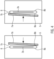
- Figure 4 shows a roughly schematic section through the separating device, for example along the line II. in Figure 2b
- the cutting edges 7a, 7b do not run parallel to the cutting edges 8b and 8a, but at an angle of 0.5° to 3°, preferably 1° to 2°. This further increases operational reliability.
- Figures 6a,b show a cross section through the transport rollers 17a, 17b, as they are shown for example in Figure 1 are shown.
- the conveyor roller 17a can have a non-cylindrical, for example, convex, outer contour
- the conveyor roller 17b can have a complementary non-cylindrical, for example, concave, outer contour. This gives the support web a corresponding shape and thus gives it even greater stability, so that the feed of the support web functions even better.
- the support web 2a is fed via the conveyor device 15 and guided through the through-opening 6 of the counter-cutting device.
- the support web 2a is cut when the knife device moves in the forward direction V and/or the counter-cutting device moves in the reverse direction R or vice versa.
- the knife device 4 or the counter-cutting device moves continuously back and forth in two directions, allowing a continuous cutting process to be realized.
- the knife device 4 and/or the counter-cutting device 5 moves further such that the feed path for the backing web 2a is again free, i.e., the through opening 6 in the exit area 11 is exposed.
- the backing web 2a can then be fed again, and the backing web 2a can be cut.
- the support web 2a is pushed between the two transport devices 12 and 13 to an upper area, whereby the fresh product 3 is pushed onto the support web 2a, 2b and carries it along.
- the support web 2a can either already be cut or, particularly if the support web is to protrude rearward under the product, it can only be cut after the fresh product 3 has already arrived.
- the device comprises a control device which controls the conveyor device 15 for feeding the support web and the transport devices 12, 13 for the fresh product as well as the separating device 1 and adapts the functions, in particular the speeds, to one another.
- the supply of fresh products can be irregular due to production reasons. Therefore, it is advantageous if the incoming fresh product, in particular the incoming fresh product portion, is detected by means of a sensor 30 (e.g., an optical sensor).
- the sensor is arranged, for example, in the area of the first transport device, here conveyor belt 12, or in an area between the transport devices 12, 13.
- the sensor can, for example, detect when the fresh product portion is incoming, i.e., detect the leading edge and forward it to the control device such that the control device knows the position of the fresh product.
- the control device then controls the conveyor device 15 for feeding the support web and the separating device 1 depending on the position detected by sensor 30.
- the length of the fresh product portion can also be determined via the sensor 30, so that in the case of fluctuating lengths of the portions, the The length of the base can be adjusted accordingly, which saves material.
- the knife device and/or the counter-cutting device can move continuously back and forth in two directions.
- the feed and cutting process can also be continuous. This results in a continuous, particularly essentially continuous, process, although the transport speed of the backing web can be constant or periodically changed, or even temporarily reduced or stopped.
Landscapes
- Engineering & Computer Science (AREA)
- Mechanical Engineering (AREA)
- Life Sciences & Earth Sciences (AREA)
- Forests & Forestry (AREA)
- Advancing Webs (AREA)
- Details Of Cutting Devices (AREA)
- Separation, Sorting, Adjustment, Or Bending Of Sheets To Be Conveyed (AREA)
- Nonmetal Cutting Devices (AREA)
- Treatment Of Fiber Materials (AREA)
Priority Applications (1)
| Application Number | Priority Date | Filing Date | Title |
|---|---|---|---|
| EP25167907.2A EP4556183A3 (fr) | 2020-06-26 | 2020-06-26 | Dispositif de séparation |
Applications Claiming Priority (2)
| Application Number | Priority Date | Filing Date | Title |
|---|---|---|---|
| EP20182610.4A EP3928936B1 (fr) | 2020-06-26 | 2020-06-26 | Dispositif de découpe |
| EP25167907.2A EP4556183A3 (fr) | 2020-06-26 | 2020-06-26 | Dispositif de séparation |
Related Parent Applications (2)
| Application Number | Title | Priority Date | Filing Date |
|---|---|---|---|
| EP20182610.4A Division EP3928936B1 (fr) | 2020-06-26 | 2020-06-26 | Dispositif de découpe |
| EP20182610.4A Division-Into EP3928936B1 (fr) | 2020-06-26 | 2020-06-26 | Dispositif de découpe |
Publications (2)
| Publication Number | Publication Date |
|---|---|
| EP4556183A2 true EP4556183A2 (fr) | 2025-05-21 |
| EP4556183A3 EP4556183A3 (fr) | 2025-08-13 |
Family
ID=71266333
Family Applications (2)
| Application Number | Title | Priority Date | Filing Date |
|---|---|---|---|
| EP20182610.4A Active EP3928936B1 (fr) | 2020-06-26 | 2020-06-26 | Dispositif de découpe |
| EP25167907.2A Pending EP4556183A3 (fr) | 2020-06-26 | 2020-06-26 | Dispositif de séparation |
Family Applications Before (1)
| Application Number | Title | Priority Date | Filing Date |
|---|---|---|---|
| EP20182610.4A Active EP3928936B1 (fr) | 2020-06-26 | 2020-06-26 | Dispositif de découpe |
Country Status (4)
| Country | Link |
|---|---|
| US (1) | US11975458B2 (fr) |
| EP (2) | EP3928936B1 (fr) |
| JP (1) | JP7314471B2 (fr) |
| CN (1) | CN113843828B (fr) |
Families Citing this family (3)
| Publication number | Priority date | Publication date | Assignee | Title |
|---|---|---|---|---|
| IT202000027989A1 (it) * | 2020-11-23 | 2022-05-23 | Ima Spa | Procedimento, dispositivo di taglio e apparecchiatura particolarmente per la fabbricazione di buste ad angoli smussati. |
| DE102021110132A1 (de) * | 2021-04-21 | 2022-10-27 | Dematic Logistics Gmbh | Verfahren zum Betreiben eines Förderers für hintereinander folgende Güter und entsprechendes Fördersystem |
| CN114890187B (zh) * | 2022-06-10 | 2023-08-08 | 江西文斌科技有限公司 | 一种基于pcb压合回流线上下铜箔输送机 |
Citations (1)
| Publication number | Priority date | Publication date | Assignee | Title |
|---|---|---|---|---|
| CN207189772U (zh) | 2017-09-20 | 2018-04-06 | 北京印刷机械研究所 | 可变尺寸横向裁切装置 |
Family Cites Families (19)
| Publication number | Priority date | Publication date | Assignee | Title |
|---|---|---|---|---|
| US3977280A (en) * | 1972-09-21 | 1976-08-31 | Geimuplast Peter Mundt Kg | Severing method and apparatus for photographic transparencies |
| GB1389774A (en) * | 1972-09-21 | 1975-04-09 | Geimuplast Mundt Kg Peter | Apparatus for severing parts from strip by a rotary knife |
| JPS54108998A (en) * | 1978-02-14 | 1979-08-27 | Hashimoto Denki Co Ltd | Continuous cutter of veneer |
| US4236855A (en) * | 1978-09-08 | 1980-12-02 | Warrick Equipment Corp. | Apparatus for and method of sequentially transporting, accumulating and stacking a predetermined number of groups of individual similar flat articles and thereafter depositing the entire stack on a conveyor |
| US4421222A (en) * | 1981-08-14 | 1983-12-20 | Planet Products Inc. | Apparatus for arranging workpieces in a predictable relationship and grouping |
| JPH0611477B2 (ja) * | 1989-03-23 | 1994-02-16 | 吉田 好枝 | 薄切り片間への密着防止片装着装置 |
| US5768857A (en) * | 1996-05-02 | 1998-06-23 | Lawrence A. Ward | Multiple perforating, automatic food preparation line having in-line foldover for food set-ups |
| US6747394B2 (en) | 2002-06-19 | 2004-06-08 | Piezomotor Uppsala Ab | Near-resonance electromechanical motor |
| AU2002313436A1 (en) * | 2002-08-20 | 2004-03-11 | Kern Ag | Transverse separating device |
| GB0515145D0 (en) * | 2005-07-23 | 2005-08-31 | Vivid Lamination Technologies | Improvements in laminating machines |
| FI119871B (fi) * | 2006-02-15 | 2009-04-30 | Raute Oyj | Viiluleikkuri |
| US8727099B2 (en) * | 2010-05-24 | 2014-05-20 | Usnr/Kockums Cancar Company | Tapered roll feed |
| DE102011103447A1 (de) * | 2011-06-07 | 2012-12-13 | Weber Maschinenbau Gmbh Breidenbach | Vorrichtung zum Fördern von blattartigem Transportgut |
| ES2551417T3 (es) * | 2012-02-14 | 2015-11-18 | Albert Handtmann Maschinenfabrik Gmbh & Co. Kg | Procedimiento y dispositivo para la separación de productos |
| DE102013216717A1 (de) * | 2013-08-22 | 2015-02-26 | Weber Maschinenbau Gmbh Breidenbach | Vorrichtung zum Aufschneiden von Lebensmittelprodukten und Verfahren zum Bereitstellen von Zwischenblättern |
| DE102014011689A1 (de) * | 2014-08-04 | 2016-02-04 | GreCon Dimter Holzoptimierung Süd GmbH & Co. KG | Vorrichtung und Verfahren zur Durchführung von Kappschnitten an Werkstücken aus Holz |
| US11167948B2 (en) * | 2015-07-22 | 2021-11-09 | Jacob Thomas LITTLEJOHNS | Waterproof dispensing apparatus for rolling paper |
| CN110002035B (zh) * | 2017-12-26 | 2021-06-01 | 南通大学 | 包装机自动推送装置工作方法 |
| CA3083695C (fr) * | 2019-05-03 | 2026-03-03 | Pacproinc, Llc | Separateur de substrat preperfore et appareil d'insertion pour substrat preperfore de la gamme de preparation alimentaire |
-
2020
- 2020-06-26 EP EP20182610.4A patent/EP3928936B1/fr active Active
- 2020-06-26 EP EP25167907.2A patent/EP4556183A3/fr active Pending
-
2021
- 2021-06-22 JP JP2021102992A patent/JP7314471B2/ja active Active
- 2021-06-24 US US17/357,721 patent/US11975458B2/en active Active
- 2021-06-28 CN CN202110717560.9A patent/CN113843828B/zh active Active
Patent Citations (1)
| Publication number | Priority date | Publication date | Assignee | Title |
|---|---|---|---|---|
| CN207189772U (zh) | 2017-09-20 | 2018-04-06 | 北京印刷机械研究所 | 可变尺寸横向裁切装置 |
Also Published As
| Publication number | Publication date |
|---|---|
| EP3928936C0 (fr) | 2025-05-21 |
| JP7314471B2 (ja) | 2023-07-26 |
| EP4556183A3 (fr) | 2025-08-13 |
| CN113843828A (zh) | 2021-12-28 |
| EP3928936A1 (fr) | 2021-12-29 |
| JP2022008202A (ja) | 2022-01-13 |
| US20210402632A1 (en) | 2021-12-30 |
| US11975458B2 (en) | 2024-05-07 |
| CN113843828B (zh) | 2023-09-29 |
| EP3928936B1 (fr) | 2025-05-21 |
Similar Documents
| Publication | Publication Date | Title |
|---|---|---|
| DE3878280T2 (de) | Bearbeitungsvorrichtung für schnellaufende Bänder. | |
| DE3217628C2 (de) | Verfahren sowie eine Vorrichtung zum Aufwickeln je eines Abschnittes von mehreren auf einander folgenden Abschnitten einer endlosen Material-Bahn | |
| DE2907203C2 (de) | Vorrichtung zum Umhüllen von Gegenständen | |
| EP3928936B1 (fr) | Dispositif de découpe | |
| EP1185398B1 (fr) | Unite d'acheminement de feuille intercalaire pour une machine a decouper un produit | |
| DE69110152T2 (de) | Apparat zum Umwickeln von Artikeln. | |
| EP1166977A1 (fr) | Machine pour la coupe automatisée d'imprimés | |
| EP1603818B1 (fr) | Procede et dispositif pour traiter une bande en papier ou en matiere pour film | |
| CH689449A5 (de) | Verfahren zum Beschneiden von flachen Druckprodukten laengs einer vorgegebenen Schnittlinie. | |
| DE2731023B2 (de) | Verfahren und Vorrichtung zum Zuschneiden von Bögen zu Einzelblättern und zum geordneten Stapeln der Einzelblätter | |
| DE69405161T2 (de) | Verfahren und Vorrichtung zum Beschicken einer Verpackungsstrasse mit Abschnitten von Wickelmaterial | |
| DE69003076T2 (de) | Vorrichtung zum fortlaufenden Schneiden von Bogenteilen aus einer Materialbahn und zum Zuführen dieser Teile zu einer Behandlungsmaschine. | |
| AT501246A1 (de) | Querschneidvorrichtung und -verfahren für bahnmaterial | |
| DE2409492A1 (de) | Vorrichtung zum ausziehen und zum einschieben von in laengsrichtung gefoerderten wellpappbahnen in querschneidervorrichtungen | |
| EP0329089A1 (fr) | Dispositif d'alimentation en papier pour une imprimante rapide utilisant des feuilles individuelles | |
| EP3283263B1 (fr) | Dispositif de coupe avec un dispositif d'insertion d'un papier intercalaire | |
| EP0133305B1 (fr) | Dispositif d'alimentation de produits en forme de barres | |
| EP3077306B1 (fr) | Dispositif et procédé de découpage d'un matériau en bande en bandes partielles et d'écartement des bandes partielles | |
| EP1854753B1 (fr) | Appareil de pliage et procédé de pliage en longueur de produits ayant une largeur variable | |
| EP1808392B1 (fr) | Procédé et dispositif destinés au traitement d'une bande de matériau à imprimer en produits accumulés | |
| DE2151728A1 (de) | Verfahren und einrichtung zum schneiden von boegen eines vorbestimmten formats aus papierbahnen od.dgl | |
| WO1995001245A1 (fr) | Procede et dispositif pour la coupe transversale de bandes de matiere | |
| EP3081354A2 (fr) | Procede et dispositif de chargement de produit de decoupe dans une machine de coupe a cotés | |
| EP4076876A1 (fr) | Procédé de coupe transversale d'une bande de matériau et dispositif associé | |
| DE29903677U1 (de) | Querschneidvorrichtung |
Legal Events
| Date | Code | Title | Description |
|---|---|---|---|
| PUAI | Public reference made under article 153(3) epc to a published international application that has entered the european phase |
Free format text: ORIGINAL CODE: 0009012 |
|
| STAA | Information on the status of an ep patent application or granted ep patent |
Free format text: STATUS: THE APPLICATION HAS BEEN PUBLISHED |
|
| AC | Divisional application: reference to earlier application |
Ref document number: 3928936 Country of ref document: EP Kind code of ref document: P |
|
| AK | Designated contracting states |
Kind code of ref document: A2 Designated state(s): AL AT BE BG CH CY CZ DE DK EE ES FI FR GB GR HR HU IE IS IT LI LT LU LV MC MK MT NL NO PL PT RO RS SE SI SK SM TR |
|
| REG | Reference to a national code |
Ref country code: DE Ref legal event code: R079 Free format text: PREVIOUS MAIN CLASS: B26D0001380000 Ipc: B26D0001000000 |
|
| PUAL | Search report despatched |
Free format text: ORIGINAL CODE: 0009013 |
|
| AK | Designated contracting states |
Kind code of ref document: A3 Designated state(s): AL AT BE BG CH CY CZ DE DK EE ES FI FR GB GR HR HU IE IS IT LI LT LU LV MC MK MT NL NO PL PT RO RS SE SI SK SM TR |
|
| RIC1 | Information provided on ipc code assigned before grant |
Ipc: B26D 1/00 20060101AFI20250709BHEP Ipc: B26D 1/06 20060101ALI20250709BHEP Ipc: B26D 1/38 20060101ALI20250709BHEP Ipc: B65B 25/06 20060101ALI20250709BHEP Ipc: B65B 61/06 20060101ALI20250709BHEP Ipc: B65B 61/20 20060101ALI20250709BHEP |
|
| STAA | Information on the status of an ep patent application or granted ep patent |
Free format text: STATUS: REQUEST FOR EXAMINATION WAS MADE |
|
| 17P | Request for examination filed |
Effective date: 20260211 |