EP4556656A1 - Fundament für einen turm mit vorgefertigter schalung, verfahren zur herstellung und installation eines solchen fundaments - Google Patents
Fundament für einen turm mit vorgefertigter schalung, verfahren zur herstellung und installation eines solchen fundaments Download PDFInfo
- Publication number
- EP4556656A1 EP4556656A1 EP23306961.6A EP23306961A EP4556656A1 EP 4556656 A1 EP4556656 A1 EP 4556656A1 EP 23306961 A EP23306961 A EP 23306961A EP 4556656 A1 EP4556656 A1 EP 4556656A1
- Authority
- EP
- European Patent Office
- Prior art keywords
- pylon
- formwork
- foundation
- excavation
- prefabricated
- Prior art date
- Legal status (The legal status is an assumption and is not a legal conclusion. Google has not performed a legal analysis and makes no representation as to the accuracy of the status listed.)
- Pending
Links
Images




Classifications
-
- E—FIXED CONSTRUCTIONS
- E04—BUILDING
- E04H—BUILDINGS OR LIKE STRUCTURES FOR PARTICULAR PURPOSES; SWIMMING OR SPLASH BATHS OR POOLS; MASTS; FENCING; TENTS OR CANOPIES, IN GENERAL
- E04H12/00—Towers; Masts or poles; Chimney stacks; Water-towers; Methods of erecting such structures
- E04H12/22—Sockets or holders for poles or posts
- E04H12/2253—Mounting poles or posts to the holder
-
- E—FIXED CONSTRUCTIONS
- E02—HYDRAULIC ENGINEERING; FOUNDATIONS; SOIL SHIFTING
- E02D—FOUNDATIONS; EXCAVATIONS; EMBANKMENTS; UNDERGROUND OR UNDERWATER STRUCTURES
- E02D27/00—Foundations as substructures
- E02D27/32—Foundations for special purposes
- E02D27/42—Foundations for poles, masts or chimneys
Definitions
- the present invention relates to a foundation for pylon foot(s) intended to be buried in an excavation. It also relates to a method of manufacturing and installing such a foundation.
- the pylons are generally made of four-legged lattices anchored to the ground on a foundation that must be able to withstand pull-out forces of 300 kN and a moment of 1000 kN.m.
- the invention aims to be able to provide a foundation suitable for this type of pylon, it applies more generally to other pylons for overhead cable transport installations or even to other pylons used in other technical fields.
- the foundation In the field of air transport and/or the distribution of electrical current, the foundation must be installed, either by digging a pit in the ground for the anchoring of a new pylon when creating or extending an overhead power line, or by replacing a pre-existing foundation when replacing a pylon or simply to reinforce this foundation.
- a first known solution for creating or replacing foundations consists of pouring concrete superficially into a previously dug excavation provided with a metal reinforcement.
- This first solution has two major drawbacks: a high risk of environmental pollution due to the large quantity of concrete that must be poured on site and possible losses of concrete in the immediate vicinity (groundwater, watercourses); a long drying time, generally reaching at least one month and then requiring guying of the pylon resting on the foundation.
- it When it is chosen to replace a pre-existing foundation, it also has two other drawbacks: dimensions of the foundation dependent on the excavation carried out, which is itself dependent on the pre-existing foundation and the ground in place; an unstable cost price due to the quantity of concrete required, which is variable.
- a second known solution for replacing foundations is, for example, recommended when a pre-existing foundation base in a solid mass must be replaced. It consists of driving two or three steel micropiles deep into the ground near each foot of the existing pylon, then welding these micropiles to the corresponding foot using metal plates, before replacing the pre-existing base with a new base. The new base is then also welded to the neighboring micropiles, then concrete is poured around the new base and the micropiles to ensure protection against corrosion. A cylindrical steel mold can be placed in the excavation for this purpose to limit the quantity of concrete to be poured around the new base and the micropiles. In any case, this second solution also has the two major drawbacks mentioned above.
- the present invention relates more specifically to a foundation for pylon foot(s) comprising prefabricated formwork intended to be buried in the excavation.
- drying time is theoretically no longer a problem and the risk of environmental pollution is reduced or even eliminated. Costs are also reduced by better control of the quantities of materials used.
- the patent document DE 1,932,594 U describes a prefabricated formwork foundation comprising a lower sole B and a side shell R1, R2 forming with the lower sole a volume inside which cables can be passed for an electrical supply to the base of the pylon to be supported.
- This The foundation is very specific and of limited use for street furniture, not very robust and not suitable for receiving an electricity pylon.
- the patent document KR 10-1236921 relates to a foundation of a tubular foot 8 of a pylon with prefabricated formwork.
- This formwork has two half-shells 2a and 2b which, when placed against each other, can be considered as comprising a lower flange, on which the pylon foot rests directly, and a lateral shell surrounding the base of the pylon foot.
- the lower flange on which the entire weight of the pylon foot rests either the latter must be of really limited weight, or the lower flange must be of very great thickness, which is not the case in the document KR 10-1236921
- This foundation is therefore also very specific and of limited use, not very robust and not suitable for receiving an electricity pylon.
- the patent document FR 2 661 701 B1 describes another type of prefabricated formwork foundation comprising a lower sole 15 and a side shell in the form of a revolution candle 16 which extends in the direction of the pylon base to be supported.
- a foundation is only partially prefabricated: the lower sole 15 remains a concrete structure to be poured into the excavation and the interior volume of the revolution candle 16 also remains to be filled with poured concrete to form a foundation block. This results in the persistent risk of environmental pollution due to the pouring of concrete and an on-site drying time to be taken into account.
- the prefabricated formwork of the foundation is lightened without compromising its robustness and without the need to pour more concrete, as the internal volume of the formwork can simply be backfilled.
- the dimensioning of the side shell is not too constrained since the support of the pylon foot(s) is done over the entire height of the side shell itself supported by the lower flange.
- This also results in a simplified, and therefore faster, installation of the foundation. Two to three days are sufficient for a replacement installation under consignment (in the case of an electricity transmission and/or distribution installation).
- the peripheral upper face capable of supporting at least one foot of the pylon is formed by the thickness of the side shell.
- the lower sole and the side shell are prefabricated in reinforced concrete.
- the lower sole and the side shell are separately prefabricated parts, which can be bolted together.
- the side shell is also formed from at least two separately prefabricated side shell portions, which can be bolted together.
- the lower sole is provided with a through drainage hole.
- the side shell is provided with at least one through hole for the passage of the earthing cable for the pylon it is intended to support.
- the side shell is essentially parallelepipedal in shape, so as to form a peripheral upper face in a rectangular frame, with a lower rectangular flange for attachment to the lower sole which itself takes the form of a rectangular plate.
- threaded rods are partially inserted into the side shell and extend orthogonally from its peripheral upper face so as to receive a base structure intended to mechanically link the prefabricated formwork and the pylon.
- Foundation 10 for pylon foot(s) shown schematically in perspective on the Figure 1 mainly comprises a prefabricated formwork 12 of essentially rectangular sections and optionally a metal base structure 14 also rectangular, carried by this formwork, intended to receive the four feet of a pylon.
- the foundation 10 is designed to be installed in a trench dug in the ground and to serve as a stable support for a pylon, with only the metal base structure 14 possibly remaining above ground after backfilling.
- the rectangular configuration of the assembly is suitable for a certain type of pylon, such as a rectangular-section metal lattice pylon with four feet anchored to the ground.
- This type of pylon corresponds to what is done for overhead transmission and/or distribution of high-voltage electrical current, for example 63 kV or 90 kV. But the configuration and dimensions of the foundation can be adapted without difficulty to other types of pylons, electrical or otherwise.
- the lower sole 16 takes the form of a rectangular plate of length L16 approximately equal to 4.5 meters, width W16 approximately equal to 2.5 meters and thickness or height H16 approximately equal to 35 centimeters for a volume of reinforced concrete C50/60 of metallic reinforcement, of classes XC2 and S4, of a little less than 4 m 3 implying a weight of approximately 9.9 tonnes.
- the first lateral half-shell 18 takes a rectangular parallelepiped shape with three solid lateral faces, forming the first lateral enclosure portion of the prefabricated formwork 12, and with the three other empty faces, so as to present a U-shaped section in top view. It further comprises a first rectangular flange 22 for fixing to the lower sole 16 extending orthogonally, from the base of the face forming the lateral bottom of the first enclosure portion, that is to say horizontally when the first lateral half-shell 18 extends vertically from the lower flange 16 arranged horizontally, towards the outside of this first portion of enclosure.
- the whole is made of material by molding concrete around a metal frame and has a maximum length L18 approximately equal to 2.1 meters, a width W18 approximately equal to 2.3 meters and a maximum height H18 approximately equal to 1.9 meters for a volume of reinforced concrete C50/60 of metal frame, of classes XC2 and S4, of a little less than 2.9 m 3 implying a weight of approximately 7.6 tons when the thickness of the first portion of enclosure and of the first flange is approximately equal to 35 centimeters, including a possibility of recesses arranged in the three faces of the first portion of enclosure.
- the second lateral half-shell 20 takes a rectangular parallelepiped shape with three full lateral faces, forming the second lateral enclosure portion of the prefabricated formwork 12, and with the three other empty faces, so as to have a U-shaped section in top view. It further comprises a second rectangular flange 24 for fixing to the lower sole 16 extending orthogonally, from the base of the face forming the lateral bottom of the second enclosure portion, towards the outside of this second enclosure portion.
- the entire prefabricated formwork 12 that these three elements 16, 18, 20 constitute weighs approximately 24.1 tonnes while each element individually weighs less than 10 tonnes.
- the subdivision into three distinct elements of the prefabricated formwork 12 thus makes it easier to transport.
- the thickness of the lateral shell made up of the two lateral half-shells 18 and 20 forms a peripheral upper face 26 in a rectangular frame capable of supporting itself at least one pylon foot.
- a rectangular frame capable of supporting itself at least one pylon foot.
- this peripheral upper face 26 delimits a rectangular central upper opening 28 of the lateral shell 18, 20 which allows it to define with the lower sole 16 an interior volume of the prefabricated formwork 12 to be backfilled.
- the first lateral half-shell 18 is fixed to the upper face of the lower sole 16 by bolting.
- its first rectangular flange 22 is pierced throughout its thickness with two rows of five conduits 30 each.
- These ten conduits 30 are intended to receive the threaded rods of ten bolting elements, for example with fixing sleeves (anchored and cast in the concrete of the lower sole 16), threaded rods (screwed into the sleeves and extending into the conduits 30), washers and nuts (screwed to the tops of the threaded rods protruding from the conduits 30), or with sleeves, washers and threaded rods with bolting heads, or any other existing and equivalent bolting variant.
- the second lateral half-shell 20 is fixed on the upper face of the lower sole 16 by bolting.
- its second rectangular flange 24 is pierced throughout its thickness with two rows of five conduits 32 each.
- These ten conduits 32 are also intended to receive the threaded rods of ten bolting elements, for example with fixing sleeves (anchored and cast in the concrete of the lower sole 16), threaded rods (screwed into the sleeves and extending into the conduits 32), washers and nuts (screwed to the tops of the threaded rods protruding from the conduits 32), or with sleeves, washers and threaded rods with bolting heads, or any other existing and equivalent bolting variant.
- niches 34 are formed in hollow at the open ends of the U-shaped section of one of the two, for example the second lateral half-shell 20 and arranged to receive suitable bolting elements, for example with fixing sleeves (anchored and cast in the concrete of the first lateral half-shell 18), perforated plates (at the ends with tabs incorporated in the concrete of the second lateral half-shell 20) and headed screws (screwed to the sleeves passing through the perforated plates).
- the lower sole 16 is shown alone on the Figure 2 according to a perspective showing its upper face for receiving the two side half-shells 18 and 20.
- the first stop 36 fulfills a longitudinal wedge function against which the first rectangular flange 22 of the first lateral half-shell 18 is positioned longitudinally
- the second stop 38 fulfills a longitudinal wedge function against which the second rectangular flange 24 of the second lateral half-shell 20 is positioned longitudinally.
- the upper face of the lower flange 16 is pierced with six holes 40 with fixing sleeves (anchored and cast in the concrete), at the rate of two series of three holes each, for the temporary fixing by bolting of two guide angles 42, 44.
- the first guide angle 42 fulfills a transverse wedge function against which the first lateral half-shell 18 is positioned transversely
- the second guide angle 44 fulfills a transverse wedge function against which the second lateral half-shell 20 is positioned transversely.
- the lower sole 16 is pierced with a through drainage hole 46. It allows the evacuation of water from the interior volume of the prefabricated formwork 12 when the latter is installed at the bottom of the excavation and backfilled.
- the upper face of the lower sole 16 is pierced with two rows of five holes 48 each.
- the ten holes 48 are equipped with the aforementioned fixing sleeves (anchored and cast in the concrete) in correspondence with the ten conduits 30 when the first lateral half-shell 18 is positioned and wedged longitudinally and transversely on the lower sole 16.
- the upper face of the lower sole 16 is pierced with two rows of five holes 50 each.
- the ten holes 50 are equipped with the aforementioned fixing sleeves (anchored and cast in the concrete) in correspondence with the ten conduits 32 when the second lateral half-shell 20 is positioned and wedged longitudinally and transversely on the lower sole 16.
- the upper face of the lower sole 16 is provided with four sockets 52 (anchored and cast in the concrete) for fixing lifting anchors.
- These four fixing sockets 52 are arranged symmetrically in a rectangle around the drainage hole 46, that is to say around the center of gravity of the lower sole 16, and as far away as possible without encroaching on the rows of holes 48 and 50. They allow the transport or movement by elevation using slings of the lower sole 16 while maintaining its balance and horizontality.
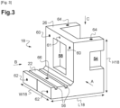
- the first side half-shell 18 is shown alone in perspective on the Figure 3 .
- first front view A it has an inverted L shape due to one of its side walls, in which a first recess or mask 54 is formed, and to its first rectangular flange 22 forming the base of the inverted L.
- two transverse channels 56 are formed in the upper face of the first rectangular flange 22, at the bottom of which extend the two rows of conduits 30 visible in the Figure 1 and invisible in the Figure 3 , in which the ten aforementioned bolting elements are intended to be housed and screwed. This allows them to be covered with a protective layer against corrosion after bolting.
- the outer bottom wall of the lateral half-shell 18 also has a recess or mask 58. It is also provided with two sockets 60 (anchored and cast in the concrete) for fixing lifting anchors in the upper left and right parts. In the upper central part, it is pierced with a through hole 61 allowing the passage of an earthing cable. This through hole 61 can also be placed lower, in the recess or mask 58 for example.
- the free lateral face of the first rectangular flange 22 is provided with two additional sockets 62 (anchored and cast in the concrete) for fixing lifting anchors in the left and right parts.
- the four fixing sockets 60 and 62 allow the transport or movement by elevation using slings of the first lateral half-shell 18 while maintaining a certain balance along a lifting axis positioned directly above its center of gravity, but positioning it at a right angle to its final position on the lower sole 16.
- the peripheral upper face portion 26 formed by the thickness of the first lateral half-shell 18 is also provided with two sockets 64 (anchored and cast in the concrete) for fixing lifting anchors on the left and right branches of the U that it forms.
- the first rectangular flange 22 is also provided with a socket 66 (anchored and cast in the concrete) for fixing a lifting anchor. The latter is centered on the upper face of the first flange 22 between the two transverse channels 56.
- the three fixing sockets 64 and 66 allow the transport or movement by elevation using slings of the first lateral half-shell 18 while retaining the final positioning that it must have on the lower sole 16.
- this elevation with three sockets 64, 66 for three lifting anchors is less assured than the previous one with four sockets 60, 62 for four lifting anchors. It is therefore suitable for an excavation of the first lateral half-shell 18 above the lower sole 16 already arranged at the bottom of the excavation, when this first lateral half-shell 18 has previously been approached close to the excavation by elevation with four lifting anchors, then straightened at a right angle.
- the second side half-shell 20 is shown alone in perspective on the Figure 4 .
- a first front view D it has an L shape due to one of its side walls, in which is formed a recess or mask 68 complementary to the recess or mask 54, and to its second rectangular flange 24 forming the base of the L.
- two transverse channels 70 are formed in the upper face of the second rectangular flange 24, at the bottom of which extend the two rows of conduits 32 visible in the Figure 1 and invisible in the Figure 4 , in which the ten aforementioned bolting elements are intended to be housed and screwed. This allows them to be covered with a protective layer against corrosion after bolting.
- the bottom inner wall of the second lateral half-shell 20 is pierced in the central upper part with a through hole 72 allowing the passage of an earthing cable.
- Its non-visible outer wall also has a recess or mask similar to the recess 58. It is also provided with two sockets similar to the sockets 60 (anchored and cast in the concrete) for fixing lifting anchors in the upper left and right parts.
- the through hole 72 can also be placed lower in the recess or mask formed in the non-visible outer wall.
- the non-visible free lateral face of the second rectangular flange 24 is provided with two additional sockets 62 (anchored and cast in the concrete) for fixing lifting anchors in the left and right parts.
- These four fixing sockets similar to the sockets 60 and 62 allow the transport or movement by elevation using slings of the second lateral half-shell 20 while maintaining a certain balance along a lifting axis positioned directly above its center of gravity, but positioning it at a right angle to its final position on the lower sole 16.
- the peripheral upper face portion 26 formed by the thickness of the second lateral half-shell 20 is also provided with two sockets 74 (anchored and cast in the concrete) for fixing lifting anchors on the left and right branches of the U that it forms.
- the second rectangular flange 24 is also provided with a socket similar to the socket 66 (anchored and cast in the concrete) for fixing the lifting anchor. The latter is centered on the upper face of the second flange 24 between the two transverse channels 70.
- These three fixing sleeves similar to the sleeves 64 and 66 allow the transport or movement by elevation using slings of the second lateral half-shell 20 while maintaining the final positioning that it must have on the lower sole 16.
- this elevation with three sleeves for three lifting anchors is less assured than the previous one with four sleeves for four lifting anchors. It is therefore suitable for an excavation of the second lateral half-shell 20 above the lower sole 16 already arranged at the bottom of the excavation, when this lateral half-shell 20 has previously been approached close to the excavation by elevation with four lifting anchors, then straightened at a right angle.
- the perspective view of the Figure 4 finally allows to clearly visualize eight niches 34 formed in hollow at the open ends of the U-shaped section of the second lateral half-shell 20 to respectively receive eight perforated plates 76 with end tabs incorporated in the concrete of the second lateral half-shell 20.
- the first lateral half-shell 18 is provided correspondingly with eight fixing sockets at the open ends of its U-shaped section not visible on the Figure 3 .
- the lower sole 16, the first lateral half-shell 18 and the second lateral half-shell 20 are shown in perspective on the Figure 5 , in their assembled configuration and assumed to be fixed by bolting, according to a view opposite that of the Figure 1 .
- threaded rods 78 are partially inserted into the concrete of the side shell 18, 20 and extend orthogonally upwards from its peripheral upper face 26. These threaded rods 78 are distributed at the four corners of the frame formed by the peripheral upper face 26 and there are four of them per corner, i.e. sixteen in all. They all have a curved lower portion housed in the reinforcement of the concrete to reinforce their insertion. On the other hand, their upper portion which comes out of the upper face peripheral 26 is straight.
- Four L-shaped plates 80 are arranged and fixed on these threaded rods 78 by double bolting using pairs of nuts, at the rate of one L-shaped plate 80 with four holes for each set of four threaded rods 78 at the four corners of the peripheral upper face 26.
- the prefabricated formwork foundation 12 When the prefabricated formwork foundation 12 is arranged approximately horizontally at the bottom of the excavation by assembling and fixing the three prefabricated parts 16, 18 and 20, its horizontality can be refined by adjusting the positioning of the four L-shaped plates 80 on the sixteen threaded rods 78 using the pairs of nuts of the double bolting.
- the threaded rods 78 allow, in cooperation with the L-shaped plates 80, to receive the metal base structure 14 visible on the Figure 1 and whose function is to mechanically link the prefabricated formwork 12 and the four feet of a pylon for which it serves as a foundation.
- This metal base structure 14 comprises four angles 82 arranged in a metal frame above the rectangular frame formed by the peripheral upper face 26 of the side shell 18, 20, resting on the four L-shaped plates 80. These four angles 82 are connected to each other and to four other angles 84 extending more or less vertically (more precisely according to the inclinations close to the vertical of the four feet of the pylon to be anchored) at the four corners of the frame using folded gussets 86 screwed onto the L-shaped plates 80 and onto all the angles 82, 84.
- the formwork 12 is prefabricated in the factory. As indicated previously for reasons of weight, it can be made up of three separately prefabricated parts in reinforced concrete, namely: the lower flange 16 forming the base of the formwork, the first lateral half-shell 18 and the second lateral half-shell 20, knowing that the two lateral half-shells 18, 20 attached to each other on the lower flange 16 and fixed by bolting form the lateral enclosure of the formwork. As already indicated, the dimensions, materials and weights which have been described in detail previously are suitable for forming the foundation of a 90 kV high-voltage power line pylon, but they are easily adaptable for other contexts, other constraints and other applications. There are numerous software tools for modeling for this purpose.
- the surface area and composition of the lower flange 16 must be sufficient to withstand the tilting moment of the pylon to be supported. By modeling, it is possible to easily determine this surface area as well as the reinforcement rate to be provided in the reinforced concrete.
- the prefabricated parts 16, 18, 20 are transported to the site, close to a pre-existing excavation or one to be carried out.
- the two lateral half-shells 18 and 20 are delivered “flat”, that is to say with a right-angle turn to the right of the first lateral half-shell 18 relative to its arrangement on the Figure 3 and to the left of the second side half-shell 20 relative to its arrangement of the Figure 4 , for security and stability reasons.
- step 104 which can be carried out independently of step 102, before, during or after, an excavation is dug (in the case of creation of a foundation for a pylon) or redeveloped (in the case of replacement of a foundation for a pylon) with an excavation bottom as horizontal as possible to accommodate the lower sole 16 of the prefabricated formwork 12.
- all the necessary ground and/or rope markings can be prepared to guide the precise positioning of the prefabricated formwork 12, so that it is correctly oriented according to the constraints that the pylon that it is intended to support will itself have to undergo.
- a subsequent step 106 the prefabricated parts 16, 18, 20 are placed on the ground.
- the two side half-shells 18, 20 are turned over at right angles to be placed in the position of the figures 3 And 4 .
- the lower sole 16 it is laid flat, its upper face upwards, and the two guide angles 42, 44 are screwed into the fixing sleeves of the six holes 40.
- Threaded guide rods can be screwed vertically into some of the fixing sleeves of the holes 48 and 50, for example three guide rods in some of the holes 48 and three guide rods in some of the holes 50.
- the lower sole 16 is transported by lifting, using slings fixed to four lifting anchors themselves screwed into the four fixing sleeves 52, also using any lifting equipment but suitable for lifting loads of up to 10 tonnes, to the bottom of the excavation.
- Two earthing cables have been previously arranged at the bottom of the excavation so as to have ends rolled into loops under the lower sole 16.
- the two lateral half-shells 18, 20 are successively transported by lifting, using slings fixed to three lifting anchors themselves screwed into the three aforementioned fixing sleeves, namely the three sleeves 64, 66 of the first lateral half-shell 18 and the three corresponding sleeves of the second lateral half-shell 20, and arranged precisely at the bottom of the excavation on the lower sole 16 by longitudinal and transverse wedging using the stops 36, 38 and the angles 42, 44.
- the threaded guide rods can then be unscrewed and removed.
- the three parts 16, 18, 20 installed at the bottom of the excavation are fixed together by bolting as detailed previously.
- each bolting element remaining visible after installation is covered with a protective layer against corrosion, for example a layer of mortar.
- the transverse channels 56, 70, as well as the niches 76 are thus filled.
- the earthing cables are introduced into the holes 61 provided for this purpose to be connected to the pylon from the interior volume of the prefabricated formwork 12.
- the two guide angles 42, 44 are unscrewed and removed.
- a subsequent step 114 the four L-shaped plates 80 are laid, adjusted and fixed as explained previously with reference to the Figure 5 .
- the metal base structure 14 is then also installed as explained previously with reference to the Figure 6 .
- a first backfilling consists of replacing and compacting earth in the excavation, around the prefabricated formwork 12 and in its interior volume, for example flush with the upper peripheral face 26 of the side shell 18, 20.
- the pylon is mounted and anchored on the prefabricated formwork foundation 12 by fixing it to the metal base structure 14.
- a surface layer of bagged concrete may optionally be provided in line with the prefabricated formwork 12 to provide mechanical protection against corrosion of at least a portion of the exposed metal elements of the foundation, namely the upper portions of the threaded rods 78 extending beyond the peripheral upper face 26, the four L-shaped plates 80 and the metal base structure 14.
- a last optional step 122 consists of carrying out a second backfilling around the surface layer of concrete added in step 120.
Landscapes
- Engineering & Computer Science (AREA)
- Civil Engineering (AREA)
- Structural Engineering (AREA)
- Architecture (AREA)
- Life Sciences & Earth Sciences (AREA)
- General Life Sciences & Earth Sciences (AREA)
- Mining & Mineral Resources (AREA)
- Paleontology (AREA)
- General Engineering & Computer Science (AREA)
- Foundations (AREA)
Priority Applications (1)
| Application Number | Priority Date | Filing Date | Title |
|---|---|---|---|
| EP23306961.6A EP4556656A1 (de) | 2023-11-14 | 2023-11-14 | Fundament für einen turm mit vorgefertigter schalung, verfahren zur herstellung und installation eines solchen fundaments |
Applications Claiming Priority (1)
| Application Number | Priority Date | Filing Date | Title |
|---|---|---|---|
| EP23306961.6A EP4556656A1 (de) | 2023-11-14 | 2023-11-14 | Fundament für einen turm mit vorgefertigter schalung, verfahren zur herstellung und installation eines solchen fundaments |
Publications (1)
| Publication Number | Publication Date |
|---|---|
| EP4556656A1 true EP4556656A1 (de) | 2025-05-21 |
Family
ID=89119270
Family Applications (1)
| Application Number | Title | Priority Date | Filing Date |
|---|---|---|---|
| EP23306961.6A Pending EP4556656A1 (de) | 2023-11-14 | 2023-11-14 | Fundament für einen turm mit vorgefertigter schalung, verfahren zur herstellung und installation eines solchen fundaments |
Country Status (1)
| Country | Link |
|---|---|
| EP (1) | EP4556656A1 (de) |
Citations (8)
| Publication number | Priority date | Publication date | Assignee | Title |
|---|---|---|---|---|
| DE1932594U (de) | 1965-06-22 | 1966-02-10 | Siemens Ag | Vorgefertigtes fundament fuer polizeirufsaeulen oder aehnliche mit kabelanschluessen ausgestattete fernmelde- oder signalsaeulen. |
| FR2661701B1 (fr) | 1990-05-02 | 1996-05-15 | Pomagalski Sa | Coffrage et massif d'ancrage d'un pylone; procede de realisation d'une fondation. |
| EP2431532A2 (de) * | 2010-09-15 | 2012-03-21 | Schuuring Mobiel B.V. | Mastbasis |
| KR101236921B1 (ko) | 2010-05-10 | 2013-02-25 | 주식회사 천지콘텍 | 울타리 지주용 조립식 콘크리트 기초블럭 |
| WO2022174913A1 (en) * | 2021-02-19 | 2022-08-25 | Rwe Renewables Gmbh | Molded part set for wind turbine foundation and wind turbine foundation |
| DE102022106027A1 (de) * | 2021-03-15 | 2022-09-22 | Westo Prefab Betonsystemen B.V. | Fundamentelement für ein mastfundament, ein mastfundament und ein verfahren zum setzen eines mastfundament |
| CN115404898A (zh) * | 2022-10-11 | 2022-11-29 | 广东电网有限责任公司 | 一种抢修塔装配式基础 |
| EP4273326A1 (de) * | 2022-05-06 | 2023-11-08 | Optum Computational Engineering ApS | Fundament für eine superstruktur, insbesondere für eine windkraftanlage, windkraftanlage mit dem fundament, verfahren zur herstellung eines windkraftanlagenfundaments |
-
2023
- 2023-11-14 EP EP23306961.6A patent/EP4556656A1/de active Pending
Patent Citations (8)
| Publication number | Priority date | Publication date | Assignee | Title |
|---|---|---|---|---|
| DE1932594U (de) | 1965-06-22 | 1966-02-10 | Siemens Ag | Vorgefertigtes fundament fuer polizeirufsaeulen oder aehnliche mit kabelanschluessen ausgestattete fernmelde- oder signalsaeulen. |
| FR2661701B1 (fr) | 1990-05-02 | 1996-05-15 | Pomagalski Sa | Coffrage et massif d'ancrage d'un pylone; procede de realisation d'une fondation. |
| KR101236921B1 (ko) | 2010-05-10 | 2013-02-25 | 주식회사 천지콘텍 | 울타리 지주용 조립식 콘크리트 기초블럭 |
| EP2431532A2 (de) * | 2010-09-15 | 2012-03-21 | Schuuring Mobiel B.V. | Mastbasis |
| WO2022174913A1 (en) * | 2021-02-19 | 2022-08-25 | Rwe Renewables Gmbh | Molded part set for wind turbine foundation and wind turbine foundation |
| DE102022106027A1 (de) * | 2021-03-15 | 2022-09-22 | Westo Prefab Betonsystemen B.V. | Fundamentelement für ein mastfundament, ein mastfundament und ein verfahren zum setzen eines mastfundament |
| EP4273326A1 (de) * | 2022-05-06 | 2023-11-08 | Optum Computational Engineering ApS | Fundament für eine superstruktur, insbesondere für eine windkraftanlage, windkraftanlage mit dem fundament, verfahren zur herstellung eines windkraftanlagenfundaments |
| CN115404898A (zh) * | 2022-10-11 | 2022-11-29 | 广东电网有限责任公司 | 一种抢修塔装配式基础 |
Similar Documents
| Publication | Publication Date | Title |
|---|---|---|
| EP2454471B1 (de) | Meereswindkraftanlage mit vertikal einstellbarem mast | |
| BE898381A (fr) | Culee de pont. | |
| EP0102340A2 (de) | Verfahren zur Herstellung von Stahlbetonbauten wie unterirdischen Strecken, Strassentunnels usw; vorgefertigte Betonelemente für die Herstellung solcher Bauten | |
| EP2642046B1 (de) | Einzäunungssystem | |
| WO1986000358A1 (fr) | Procede et appareillage pour la realisation d'une dalle rigide permettant de porter une construction | |
| EP4556656A1 (de) | Fundament für einen turm mit vorgefertigter schalung, verfahren zur herstellung und installation eines solchen fundaments | |
| EP0242497B1 (de) | Tunnelbauverfahren | |
| FR2789706A1 (fr) | Procede d'etanconnement a l'aide de piliers de renfort d'une structure a parois verticales et pilier a cet effet | |
| EP0093030B1 (de) | Tiefraum, insbesondere ein Keller und Einrichtungsverfahren desselben | |
| FR2668029A3 (fr) | Dispositif pour recouvrir les fosses de plantation d'arbres dans les surfaces de circulation. | |
| FR2824851A1 (fr) | Appui de pont prefabrique | |
| EP0767881A1 (de) | Flüssigkeitsrohr | |
| MC823A1 (fr) | Procédé de construction d'un bâtiment partiellement submergé et bâtiment réalisé suivant ce procédé | |
| FR2727447A1 (fr) | Ouvrage de passage sous remblai et son procede de realisation | |
| EP0305259B1 (de) | Verfahren zum Stützen der Seitenwände von Tiefgruben | |
| FR2871824A1 (fr) | Elements-cadres prefabriques pour la realisation de tunnels et de canaux et son application a des bassins de reserve d'eau de type enterre, semi-enterre ou non enterre | |
| FR2797288A1 (fr) | Dispositif de fondations ancrees dans le sol par damage | |
| CA2087455C (fr) | Methode de remplacement d'une chambre de raccordement enfouie dans le sol et kit de remplacement | |
| WO1990001089A1 (fr) | Procede pour reparer une fondation comportant des tetes de pieux deteriorees, notamment de pieux en bois | |
| FR2846676A1 (fr) | Fondations d'un pylone ou similaire | |
| BE876763A (fr) | Procede et dispositif de soutenement d'un edifice a partir d'une galerie souterraine. | |
| FR2627789A1 (fr) | Bloc de soutien en beton prefabrique pour poteaux | |
| FR2627792A1 (fr) | Tribunes en gradins couvertes et procedes de construction | |
| FR2737515A1 (fr) | Dispositif de maintien et de coffrage pour reseaux de distribution souterrains, en particulier electriques, telephoniques, cables, ou autres | |
| FR2648841A1 (fr) | Procede de reprise en sous-oeuvre |
Legal Events
| Date | Code | Title | Description |
|---|---|---|---|
| PUAI | Public reference made under article 153(3) epc to a published international application that has entered the european phase |
Free format text: ORIGINAL CODE: 0009012 |
|
| STAA | Information on the status of an ep patent application or granted ep patent |
Free format text: STATUS: THE APPLICATION HAS BEEN PUBLISHED |
|
| AK | Designated contracting states |
Kind code of ref document: A1 Designated state(s): AL AT BE BG CH CY CZ DE DK EE ES FI FR GB GR HR HU IE IS IT LI LT LU LV MC ME MK MT NL NO PL PT RO RS SE SI SK SM TR |
|
| P01 | Opt-out of the competence of the unified patent court (upc) registered |
Free format text: CASE NUMBER: APP_27410/2025 Effective date: 20250610 |
|
| STAA | Information on the status of an ep patent application or granted ep patent |
Free format text: STATUS: REQUEST FOR EXAMINATION WAS MADE |
|
| 17P | Request for examination filed |
Effective date: 20251121 |