EP4556870A1 - System und verfahren zur kalibrierung von optischen messvorrichtungen - Google Patents
System und verfahren zur kalibrierung von optischen messvorrichtungen Download PDFInfo
- Publication number
- EP4556870A1 EP4556870A1 EP24211319.9A EP24211319A EP4556870A1 EP 4556870 A1 EP4556870 A1 EP 4556870A1 EP 24211319 A EP24211319 A EP 24211319A EP 4556870 A1 EP4556870 A1 EP 4556870A1
- Authority
- EP
- European Patent Office
- Prior art keywords
- projection
- optical measurement
- measurement device
- calibration
- standard
- Prior art date
- Legal status (The legal status is an assumption and is not a legal conclusion. Google has not performed a legal analysis and makes no representation as to the accuracy of the status listed.)
- Pending
Links
Images

Classifications
-
- G—PHYSICS
- G01—MEASURING; TESTING
- G01J—MEASUREMENT OF INTENSITY, VELOCITY, SPECTRAL CONTENT, POLARISATION, PHASE OR PULSE CHARACTERISTICS OF INFRARED, VISIBLE OR ULTRAVIOLET LIGHT; COLORIMETRY; RADIATION PYROMETRY
- G01J3/00—Spectrometry; Spectrophotometry; Monochromators; Measuring colours
- G01J3/46—Measurement of colour; Colour measuring devices, e.g. colorimeters
- G01J3/463—Colour matching
-
- G—PHYSICS
- G01—MEASURING; TESTING
- G01M—TESTING STATIC OR DYNAMIC BALANCE OF MACHINES OR STRUCTURES; TESTING OF STRUCTURES OR APPARATUS, NOT OTHERWISE PROVIDED FOR
- G01M11/00—Testing of optical apparatus; Testing structures by optical methods not otherwise provided for
- G01M11/02—Testing optical properties
- G01M11/0242—Testing optical properties by measuring geometrical properties or aberrations
- G01M11/0257—Testing optical properties by measuring geometrical properties or aberrations by analyzing the image formed by the object to be tested
-
- G—PHYSICS
- G01—MEASURING; TESTING
- G01B—MEASURING LENGTH, THICKNESS OR SIMILAR LINEAR DIMENSIONS; MEASURING ANGLES; MEASURING AREAS; MEASURING IRREGULARITIES OF SURFACES OR CONTOURS
- G01B11/00—Measuring arrangements characterised by the use of optical techniques
- G01B11/24—Measuring arrangements characterised by the use of optical techniques for measuring contours or curvatures
- G01B11/25—Measuring arrangements characterised by the use of optical techniques for measuring contours or curvatures by projecting a pattern, e.g. one or more lines, moiré fringes on the object
- G01B11/2504—Calibration devices
-
- G—PHYSICS
- G01—MEASURING; TESTING
- G01M—TESTING STATIC OR DYNAMIC BALANCE OF MACHINES OR STRUCTURES; TESTING OF STRUCTURES OR APPARATUS, NOT OTHERWISE PROVIDED FOR
- G01M11/00—Testing of optical apparatus; Testing structures by optical methods not otherwise provided for
- G01M11/02—Testing optical properties
- G01M11/0207—Details of measuring devices
-
- G—PHYSICS
- G01—MEASURING; TESTING
- G01M—TESTING STATIC OR DYNAMIC BALANCE OF MACHINES OR STRUCTURES; TESTING OF STRUCTURES OR APPARATUS, NOT OTHERWISE PROVIDED FOR
- G01M11/00—Testing of optical apparatus; Testing structures by optical methods not otherwise provided for
- G01M11/02—Testing optical properties
- G01M11/0242—Testing optical properties by measuring geometrical properties or aberrations
- G01M11/0257—Testing optical properties by measuring geometrical properties or aberrations by analyzing the image formed by the object to be tested
- G01M11/0264—Testing optical properties by measuring geometrical properties or aberrations by analyzing the image formed by the object to be tested by using targets or reference patterns
-
- G—PHYSICS
- G03—PHOTOGRAPHY; CINEMATOGRAPHY; ANALOGOUS TECHNIQUES USING WAVES OTHER THAN OPTICAL WAVES; ELECTROGRAPHY; HOLOGRAPHY
- G03B—APPARATUS OR ARRANGEMENTS FOR TAKING PHOTOGRAPHS OR FOR PROJECTING OR VIEWING THEM; APPARATUS OR ARRANGEMENTS EMPLOYING ANALOGOUS TECHNIQUES USING WAVES OTHER THAN OPTICAL WAVES; ACCESSORIES THEREFOR
- G03B23/00—Devices for changing pictures in viewing apparatus or projectors
- G03B23/08—Devices for changing pictures in viewing apparatus or projectors in which pictures are attached to a movable carrier
- G03B23/10—Devices for changing pictures in viewing apparatus or projectors in which pictures are attached to a movable carrier drum or disc carrier
- G03B23/105—Devices for changing pictures in viewing apparatus or projectors in which pictures are attached to a movable carrier drum or disc carrier disc carriers
-
- H—ELECTRICITY
- H04—ELECTRIC COMMUNICATION TECHNIQUE
- H04N—PICTORIAL COMMUNICATION, e.g. TELEVISION
- H04N13/00—Stereoscopic video systems; Multi-view video systems; Details thereof
- H04N13/30—Image reproducers
- H04N13/327—Calibration thereof
-
- G—PHYSICS
- G01—MEASURING; TESTING
- G01J—MEASUREMENT OF INTENSITY, VELOCITY, SPECTRAL CONTENT, POLARISATION, PHASE OR PULSE CHARACTERISTICS OF INFRARED, VISIBLE OR ULTRAVIOLET LIGHT; COLORIMETRY; RADIATION PYROMETRY
- G01J3/00—Spectrometry; Spectrophotometry; Monochromators; Measuring colours
- G01J3/02—Details
- G01J3/10—Arrangements of light sources specially adapted for spectrometry or colorimetry
Definitions
- the present disclosure relates to a system and a method for calibration of optical measurement devices, and in particular, to a calibration system and method, which can provide a standard image for an optical measurement device to be calibrated, facilitating analysis and calibration on a measurement result of the optical measurement device.
- Optical measurement devices are commonly used for measuring various display performance of light sources of various displays and lighting devices. For example, they can provide measurements of various optical characteristics such as chromaticity, luminance, contrast, uniformity, and correlated color temperature of various displays.
- the device typically has to be disassembled from the machine and sent back to the manufacturer for calibration, or moved to a professional laboratory with fewer space constraints for recalibration. This process is often time-consuming.
- the calibration process requires preparation of an integrating sphere and specific physical images, and this calibration must take place in a relatively large space.
- the imaging lens may need to be positioned 10 meters away from the object being measured, which means that the specific physical image must be extremely large in size.
- embodiments of the present disclosure provide a system and a method for calibration of optical measurement devices, which can completely solve the problems of the above-mentioned conventional technology.
- An embodiment of the present disclosure provides a system for calibration of an optical measurement device.
- the optical measurement device includes an imaging lens.
- the calibration system includes a standard projection device, and the device comprises (but is not limited to): a projection light source, a lens module, and at least one projection element.
- An optical axis of the lens module is aligned with an optical axis of the imaging lens, and the at least one projection element is located between the projection light source and the lens module.
- the light emitted from the projection light source passes through the at least one projection element and is projected by the lens module, and then captured by the imaging lens of the optical measurement device.
- An exit pupil of the lens module of the standard projection device is coincident with an entrance pupil of the imaging lens of the optical measurement device.
- An embodiment of the present disclosure provides a method for calibration of an optical measurement device.
- the optical measurement device includes an imaging lens.
- the method includes (but is not limited to) the following steps: firstly, aligning an optical axis of a standard projection device with an optical axis of the imaging lens, and making an exit pupil of the standard projection device to be coincident with an entrance pupil of the optical measurement device; then, projecting a standard image by the standard projection device, and capturing the standard image by the optical measurement device; and performing at least one of analyzing and calibrating the captured standard image by the optical measurement device.
- FIG. 1A is an architecture diagram of an embodiment of the present disclosure
- FIG. 1B is a schematic diagram of an embodiment of the present disclosure
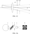
- FIG. 1C is a schematic diagram of an exit pupil ExP and an entrance pupil EnP in an optical system
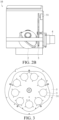
- FIG. 2A is a schematic diagram of a standard projection device 10 according to an embodiment of the present disclosure
- FIG. 2B is a sectional view of a standard projection device 10 according to an embodiment of the present disclosure.
- FIG. 1B merely illustrates, in a schematic form, the concept of the exit pupil ExP of the standard projection device 10 being coincident with the entrance pupil EnP of the optical measurement device CM.
- This figure is not a depiction of an actual optical system configuration.
- FIG. 2A only schematically presents a relative position relationship of the main components inside the standard projection device 10, as well as the projection effect of the standard image Si related to the projection element 3 within the standard projection device 10. It is not an actual configuration diagram of the internal components of the standard projection device 10.
- FIG. 2A for the sake of clearly presenting the projection relationship among the projection light source 2, the projection element 3, and the standard image Si, the arrangement orientations of the projection light source 2 and the projection element 3 differs from that of other components shown in the figure
- the optical measurement device mentioned in the following embodiments may be specialized equipment for measuring or inspecting the display performance of near-eye display devices (NED), such as augmented reality (AR), virtual reality (VR), and mixed reality (MR) devices.
- NED near-eye display devices
- AR augmented reality
- VR virtual reality
- MR mixed reality
- the scope is not limited to this; the calibration system and method of the present disclosure are applicable to any optical measurement device capable of measuring optical characteristics such as chromaticity, luminance, contrast, uniformity, and correlated color temperature of various displays, lighting devices, or any other light-emitting devices.
- the optical measurement device CM in the embodiment includes an imaging lens CL, which may consist of optical components such as a macro lens, a baffle, an aperture assembly, and an eyepiece.
- an imaging lens CL which may consist of optical components such as a macro lens, a baffle, an aperture assembly, and an eyepiece.
- the calibration system 1 for an optical measurement device may include the standard projection device 10 and a main controller 7.
- the standard projection device 10 may further comprise: a projection light source 2, a lens module 4, a turntable 5, a driver 51, and an aperture assembly 6.
- the projection light source 2 is a standard projection light source capable of providing a uniform light source (RGBW), such as an integrating sphere light source.
- the lens module 4 can be a projection lens including lens components such as the macro lens and the baffle.
- FIG. 3 is a front view of a turntable 5 according to an embodiment of the present disclosure.
- the turntable 5 is provided with a plurality of apertures 31, and various projection elements 3 can be placed within the aperture. Examples include monochrome (black, white, gray) projection elements, black-and-white checkerboard projection elements, RGB primary color projection elements, and RGB checkerboard projection elements.
- Each projection element corresponds to at least one calibration item for optical characteristics, which will be detailed later.
- one aperture 31 can be arranged in a hollow manner, and no projection element 3 is arranged.
- one of the apertures 31 may be left empty without any projection element 3.
- the projection element 3 may be a slide with a specific pattern printed on a transparent film.
- the driver 51 is used to drive the turntable 5 to rotate, and is coupled with a reduction gear to allow the projection elements 3 on the turntable 5 to be aligned with the projection light source 2 and the lens module 4.
- the aperture assembly 6 is arranged between the turntable 5 and the lens module 4. Therefore, the light emitted from the projection light source 2 can pass through the projection elements 3, and is projected as a standard image Si by the lens module 4 via the aperture assembly 6.
- the standard image Si is associated with the projection elements 3, that is, the content included in the projection object 3, as schematically shown in FIG. 2A .
- the main controller 7 can be any single or multiple processor computing devices or systems capable of executing computer-readable instructions. Examples include, but are not limited to: a workstation, a laptop, a client terminal, a server, or a distributed computing system, a handheld device, or any other computing system or device. In the most basic configuration, the main controller 7 may include at least one processor and a system memory.
- the main controller 7 is electrically connected to the projection light source 2 and the driver 51 of the standard projection device 10, and the optical measurement device CM.
- the main controller 7 is mainly used to control the activation or deactivation of the projection light source 2 and the driver 51, as well as to control the optical measurement device CM in capturing and analyzing the standard image Si.
- the calibration principle in one embodiment of the present disclosure accords with at least the following two prerequisites: (1) the optical axis of the lens module 4 is aligned with the optical axis of the imaging lens CL; and (2) the exit pupil ExP of the lens module 4 is coincident with the entrance pupil EnP of the imaging lens CL.
- prerequisite (2) this can be achieved after the optical axis alignment of prerequisite (1) by adjusting the horizontal axial distance between the standard projection device 10 and the optical measurement device CM. In one embodiment, this adjustment is made by moving the standard projection device 10 closer to or farther from the imaging lens CL.
- determining whether the exit pupil ExP of the lens module 4 is coincident with the entrance pupil EnP of the imaging lens CL this can be judged by the size of the image (field of view, FOV) captured by the optical measurement device CM. When the image size (FOV) reaches a preset value, it can be determined that the exit pupil ExP of the lens module 4 is coincident with the entrance pupil EnP of the imaging lens CL.
- FOV field of view
- the "exit pupil ExP" can be defined as the effective aperture that limits the outgoing light beam, which is the image formed by the aperture stop AP on the rear optical system. More simply, the exit pupil ExP determines the angular range of the light exiting the optical system.
- the term “entrance pupil EnP” can be defined as the image of the aperture stop AP formed in object space by the preceding lens group in the optical system, with its primary function being to limit the effective aperture of the incoming light beam. More simply, the entrance pupil EnP determines the angular range of the light entering the optical system.
- the point labeled "F" in FIG. 1C represents the focal point.
- the optical measurement device CM is used to measure a near-eye display devices (not shown in the figure)
- its imaging focal position is set at infinity
- the entrance pupil EnP of the imaging lens CL is preset to be 1cm to 2cm in front of the lens, similar to the distance between the display module and the human eye when a near-eye display device is worn by a user.
- the projection imaging position of the lens module 4 of the standard projection device 10 is also set to infinity, so the exit pupil ExP of the lens module 4 is also positioned 1cm to 2cm in front of the lens.
- achieving the coincidence of the exit pupil ExP of the lens module 4 with the entrance pupil EnP of the imaging lens CL, as shown by distance D in FIG. 1A can be accomplished simply by positioning the lens module 4 and the imaging lens CL 1cm to 2cm apart.
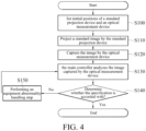
- Step S100 initial positions of the standard projection device 10 and the optical measurement device CM are set. Specifically, the optical axis of the lens module 4 is aligned with the optical axis of the imaging lens CL; and the exit pupil ExP of the lens module 4 is made to coincide with the entrance pupil EnP of the imaging lens CL.
- the main controller 7 controls the standard projection device 10 to project a standard image Si, which is associated with a quality item to be inspected as described in step S110.
- the main controller 7 controls the optical measurement device CM to capture the standard image Si, as described in step S120.
- the main controller 7 analyzes the image captured by the optical measurement device CM and determines whether the image accords with the specification, as described in step S130 and step S140.
- the inspection process for this measurement quality item is terminated, and the inspection process for the next measurement quality item can be performed.
- the driver 51 can drive the turntable 5 to rotate so that another projection element 3 is aligned with the projection light source 2 and the lens module 4, and steps S110 to S140 are repeated.
- step S150 the equipment abnormality handling step, is performed, in which the main controller 7 records and reports an abnormal status, and the use of the optical measurement device CM is temporarily suspended.
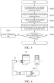
- FIG. 5 is a flowchart of a method for calibrating the measurement quality of an optical measurement device according to an embodiment of the present disclosure.
- the main difference between the method for calibrating in the present embodiment and the method for inspecting in the above-mentioned embodiment is that this embodiment can establish a calibration file for measurement quality items that do not meet the specifications for subsequent calibration, as shown in step S250.
- the main controller 7 can also directly perform automatic adjustment on the measurement items that do not meet the specifications, such as automatically compensating (digital processing) for subsequent captured images, thereby realizing an automatic calibration function.
- the other steps they are the same as those in the previous embodiments, and will not be described in detail.
- the standard projection device 10 projects a pure-color standard image Si using a monochrome (such as black, white, gray, red, blue, or green) projection element, and the optical measurement device CM captures the image. If the main controller 7 determines that the captured image shows a local pixel area with a display mode different from that of other areas, the main controller 7 can determine that the local pixel area is a defective pixel area
- the standard projection device 10 can utilize a projection element 3 with a checkerboard pattern to project a standard image Si with a checkerboard pattern (as shown in Figure 2A ), which is then captured by the optical measurement device CM.
- the projection element 3 with a checkerboard pattern can also take the form of a reticle. When light passes through the reticle, bright light spots appear, and when light cannot pass through the reticle, dark spots appear.
- the main controller 7 analyzes the captured image to determine whether the boundaries of the checkerboard pattern are distorted or deformed, and thereby determines whether the inspection results meet the standard specifications.
- the main controller 7 can also perform an automatic correction function, that is, using software algorithms to process the distorted and deformed portions of the image to make them appear like the checkerboard pattern in the standard image Si.
- the standard projection device 10 can project a pure color standard image Si such as red, green, or blue, use a red, green, or blue (RGB) three-color pure-color projection element, or utilize a hollow configuration to directly project a pure-color image through an integrating sphere light source (the projection light source 2), and the image is captured through the optical measurement device CM; and then, the main controller 7 can analyze the chromaticity and hue of the received pure-color standard image Si, and accordingly determine whether the inspection result accords with the standard specification. For chromaticity and hue analysis calibrations, the standard projection device 10 can project pure-color standard images Si in red, green, or blue.
- a pure color standard image Si such as red, green, or blue
- RGB red, green, or blue
- These pure-color images can be projected through red, green, and blue (RGB) projection elements, or alternatively, a perforated configuration can be used to directly project the pure-color images from an integrating sphere light source (projection light source 2).
- the optical measurement device CM captures the image, and the main controller 7 analyzes the chromaticity and hue of the received pure-color standard image Si to determine whether the inspection results meet the standard specifications.
- the standard projection device 10 can utilize a projection element 3 with an RGB (red, green, and blue) checkerboard pattern to project a standard image Si with an RGB checkerboard pattern.
- the RGB checkerboard pattern projection element 3 can also take the form of a reticle.
- the projection light source 2 directly emits red, green, or blue light; when the red, green, or blue light passes through the reticle, a bright spot of the corresponding color appears, and when the light cannot pass through the reticle, a dark spot appears.
- the main controller 7 analyzes the captured image to determine whether there is any color shift, and thereby determines whether the inspection results meet the standard specifications.
- the edges of the checkerboard pattern can be specifically identified and analyzed, as color shifts are more easily observed at these locations.
- the standard projection device 10 can similarly utilize a projection element 3 with a checkerboard pattern to project a standard image Si with a checkerboard pattern (as shown in FIG. 2A ), which is then captured by the optical measurement device CM.
- the projection element 3 with a checkerboard pattern can also take the form of a reticle. When light passes through the reticle, bright light spots appear, and when light cannot pass through the reticle, dark spots appear. Subsequently, the main controller 7 analyzes the captured image to determine whether the checkerboard pattern has undergone any displacement or rotation, thereby determining whether the inspection results meet the standard specifications.
Landscapes
- Physics & Mathematics (AREA)
- General Physics & Mathematics (AREA)
- Chemical & Material Sciences (AREA)
- Analytical Chemistry (AREA)
- Engineering & Computer Science (AREA)
- Geometry (AREA)
- Spectroscopy & Molecular Physics (AREA)
- Multimedia (AREA)
- Signal Processing (AREA)
- Computer Vision & Pattern Recognition (AREA)
- Testing Of Optical Devices Or Fibers (AREA)
- Photometry And Measurement Of Optical Pulse Characteristics (AREA)
Applications Claiming Priority (1)
| Application Number | Priority Date | Filing Date | Title |
|---|---|---|---|
| TW112144160A TWI870105B (zh) | 2023-11-15 | 2023-11-15 | 光學量測裝置之校正系統及方法 |
Publications (1)
| Publication Number | Publication Date |
|---|---|
| EP4556870A1 true EP4556870A1 (de) | 2025-05-21 |
Family
ID=93455989
Family Applications (1)
| Application Number | Title | Priority Date | Filing Date |
|---|---|---|---|
| EP24211319.9A Pending EP4556870A1 (de) | 2023-11-15 | 2024-11-07 | System und verfahren zur kalibrierung von optischen messvorrichtungen |
Country Status (3)
| Country | Link |
|---|---|
| US (1) | US20250155319A1 (de) |
| EP (1) | EP4556870A1 (de) |
| TW (1) | TWI870105B (de) |
Citations (3)
| Publication number | Priority date | Publication date | Assignee | Title |
|---|---|---|---|---|
| JPS5980965A (ja) * | 1982-10-29 | 1984-05-10 | Matsushita Electric Ind Co Ltd | 固体撮像素子検査装置 |
| JP2003279446A (ja) * | 2002-03-25 | 2003-10-02 | Seiko Epson Corp | 撮像用レンズ検査装置、および撮像用レンズ検査方法 |
| US20060274275A1 (en) * | 2002-05-20 | 2006-12-07 | Bremer James C | Wide field collimator |
Family Cites Families (13)
| Publication number | Priority date | Publication date | Assignee | Title |
|---|---|---|---|---|
| TW200412149A (en) * | 2002-12-27 | 2004-07-01 | Veutron Corp | Method and device using several calibration lines for correcting shading distortion |
| JP6590249B2 (ja) * | 2015-09-09 | 2019-10-16 | 株式会社リコー | 画像投写装置 |
| CA3079507C (en) * | 2016-10-18 | 2022-10-18 | Gamma Scientific Inc. | Apparatus and method for multi configuration near eye display performance characterization |
| EP3318915B1 (de) * | 2016-11-04 | 2020-04-22 | Essilor International | Verfahren zur bestimmung einer optischen leistung einer kopfmontierten anzeigevorrichtung |
| US10402950B1 (en) * | 2016-11-15 | 2019-09-03 | Facebook Technologies, Llc | Optical measurement system |
| CN106595482B (zh) * | 2016-12-14 | 2019-06-04 | 海信集团有限公司 | 激光投影系统的光斑测量方法及装置 |
| CN107884160A (zh) * | 2017-09-25 | 2018-04-06 | 杭州浙大三色仪器有限公司 | 虚拟图像光电测量仪 |
| IL275013B (en) * | 2017-12-03 | 2022-08-01 | Lumus Ltd | Optical device testing method and apparatus |
| US20200033595A1 (en) * | 2018-07-24 | 2020-01-30 | North Inc. | Method and system for calibrating a wearable heads-up display having multiple exit pupils |
| US20200080913A1 (en) * | 2018-09-11 | 2020-03-12 | Rockwell Automation Technologies, Inc. | Compact lens tester |
| CN113311665B (zh) * | 2020-02-27 | 2023-04-07 | 上海微电子装备(集团)股份有限公司 | 定位系统、定位方法及干涉仪的验证方法 |
| EP4314754A4 (de) * | 2021-03-23 | 2025-01-29 | Radiant Vision Systems, LLC | Bildgebungssysteme mit bildgebungssystemen für ar/vr-vorrichtungen und zugehörige systeme, vorrichtungen und verfahren |
| DE102023205136A1 (de) * | 2023-06-01 | 2024-12-05 | Carl Zeiss Smt Gmbh | Verfahren zum Nachbilden von Beleuchtungs- und Abbildungseigenschaften eines optischen Produktionssystems bei der Beleuchtung und Abbildung eines Objekts mittels eines optischen Messsystems |
-
2023
- 2023-11-15 TW TW112144160A patent/TWI870105B/zh active
-
2024
- 2024-10-30 US US18/931,867 patent/US20250155319A1/en active Pending
- 2024-11-07 EP EP24211319.9A patent/EP4556870A1/de active Pending
Patent Citations (3)
| Publication number | Priority date | Publication date | Assignee | Title |
|---|---|---|---|---|
| JPS5980965A (ja) * | 1982-10-29 | 1984-05-10 | Matsushita Electric Ind Co Ltd | 固体撮像素子検査装置 |
| JP2003279446A (ja) * | 2002-03-25 | 2003-10-02 | Seiko Epson Corp | 撮像用レンズ検査装置、および撮像用レンズ検査方法 |
| US20060274275A1 (en) * | 2002-05-20 | 2006-12-07 | Bremer James C | Wide field collimator |
Non-Patent Citations (1)
| Title |
|---|
| ANONYMOUS: "OptiTest a complete range of Optical Instruments 1 @BULLET OPTITEST -a modular Optical Test Equipment", 3 May 2013 (2013-05-03), XP055610622, Retrieved from the Internet <URL:https://www.trioptics.com/fileadmin/assets/trioptics/04_Downloads/OptiTest/OptiTest-Product-Brochure-E.pdf> [retrieved on 20190802] * |
Also Published As
| Publication number | Publication date |
|---|---|
| TW202521954A (zh) | 2025-06-01 |
| TWI870105B (zh) | 2025-01-11 |
| US20250155319A1 (en) | 2025-05-15 |
Similar Documents
| Publication | Publication Date | Title |
|---|---|---|
| US8634014B2 (en) | Imaging device analysis systems and imaging device analysis methods | |
| US6824271B2 (en) | Multiprojection system and method of acquiring correction data in multiprojection system | |
| CN112885289B (zh) | 一种显示屏的校准方法及设备 | |
| US10863069B2 (en) | Image processing system and setting method | |
| TW557354B (en) | Lens inspection equipment and inspection sheet | |
| TWI484283B (zh) | 影像計算量測方法、影像計算量測裝置及影像檢查裝置 | |
| JP2010522347A (ja) | オプトエレクトロニクス情報を表示する様々なタイプの装置の動作に関連する複数のパラメータを制御するユニバーサルテストシステム | |
| KR20050051535A (ko) | 결함 검사 장치 | |
| KR20250116144A (ko) | 검사 항목에 대한 적어도 하나의 이미지의 이미징 품질을 결정하기 위한 디바이스 및 방법 | |
| JP2014035261A (ja) | 情報処理方法、情報処理装置、プログラム、撮像装置、検査方法、検査装置、及び基板の製造方法 | |
| CN117990346B (zh) | 一种散斑测量分析设备及方法 | |
| US20160165200A1 (en) | Measurements of cinematographic projection | |
| US10444162B2 (en) | Method of testing an object and apparatus for performing the same | |
| JP2017528762A (ja) | デジタル顕微鏡の色再現を修正する方法、ならびにデジタル顕微鏡 | |
| CN111638042B (zh) | 一种dlp光学特性测试分析方法 | |
| EP4556870A1 (de) | System und verfahren zur kalibrierung von optischen messvorrichtungen | |
| CN110389020A (zh) | 空间光调制器的检测方法 | |
| US11245881B2 (en) | Method and apparatus for correcting color convergence error | |
| US10733750B2 (en) | Optical characteristics measuring method and optical characteristics measuring system | |
| JP2007329591A (ja) | 輝度及び色度測定における校正方法 | |
| CN120008881A (zh) | 光学测量装置的校正系统及方法 | |
| CN110174351B (zh) | 颜色测量装置及方法 | |
| JPH08114503A (ja) | 色測定装置 | |
| JPH08320273A (ja) | 光学的角度特性測定装置 | |
| CN112782082B (zh) | 一种用于线扫描成像的定标装置和方法 |
Legal Events
| Date | Code | Title | Description |
|---|---|---|---|
| PUAI | Public reference made under article 153(3) epc to a published international application that has entered the european phase |
Free format text: ORIGINAL CODE: 0009012 |
|
| STAA | Information on the status of an ep patent application or granted ep patent |
Free format text: STATUS: THE APPLICATION HAS BEEN PUBLISHED |
|
| AK | Designated contracting states |
Kind code of ref document: A1 Designated state(s): AL AT BE BG CH CY CZ DE DK EE ES FI FR GB GR HR HU IE IS IT LI LT LU LV MC ME MK MT NL NO PL PT RO RS SE SI SK SM TR |
|
| STAA | Information on the status of an ep patent application or granted ep patent |
Free format text: STATUS: REQUEST FOR EXAMINATION WAS MADE |
|
| 17P | Request for examination filed |
Effective date: 20251009 |