EP0953858A1 - Faseroptische Bandleitung und faseroptisches Bandkabel - Google Patents
Faseroptische Bandleitung und faseroptisches Bandkabel Download PDFInfo
- Publication number
- EP0953858A1 EP0953858A1 EP99400981A EP99400981A EP0953858A1 EP 0953858 A1 EP0953858 A1 EP 0953858A1 EP 99400981 A EP99400981 A EP 99400981A EP 99400981 A EP99400981 A EP 99400981A EP 0953858 A1 EP0953858 A1 EP 0953858A1
- Authority
- EP
- European Patent Office
- Prior art keywords
- section
- optical fiber
- matrix material
- planar surface
- material coating
- Prior art date
- Legal status (The legal status is an assumption and is not a legal conclusion. Google has not performed a legal analysis and makes no representation as to the accuracy of the status listed.)
- Withdrawn
Links
- 239000013307 optical fiber Substances 0.000 claims abstract description 128
- 239000011159 matrix material Substances 0.000 claims abstract description 72
- 238000000576 coating method Methods 0.000 claims abstract description 49
- 239000011248 coating agent Substances 0.000 claims abstract description 47
- 239000000314 lubricant Substances 0.000 claims description 3
- 239000000835 fiber Substances 0.000 description 14
- 239000010410 layer Substances 0.000 description 8
- 238000010586 diagram Methods 0.000 description 7
- 238000000034 method Methods 0.000 description 6
- 239000003292 glue Substances 0.000 description 4
- 239000004033 plastic Substances 0.000 description 4
- 239000000853 adhesive Substances 0.000 description 3
- 230000001070 adhesive effect Effects 0.000 description 3
- 239000002390 adhesive tape Substances 0.000 description 2
- 239000003795 chemical substances by application Substances 0.000 description 2
- 239000000049 pigment Substances 0.000 description 2
- 230000000903 blocking effect Effects 0.000 description 1
- 238000005253 cladding Methods 0.000 description 1
- 239000011247 coating layer Substances 0.000 description 1
- 238000004040 coloring Methods 0.000 description 1
- 150000001875 compounds Chemical class 0.000 description 1
- 238000010276 construction Methods 0.000 description 1
- 230000032798 delamination Effects 0.000 description 1
- 239000000463 material Substances 0.000 description 1
- 230000003287 optical effect Effects 0.000 description 1
- 238000012856 packing Methods 0.000 description 1
- 229920002545 silicone oil Polymers 0.000 description 1
- 239000000126 substance Substances 0.000 description 1
- 239000000758 substrate Substances 0.000 description 1
- XLYOFNOQVPJJNP-UHFFFAOYSA-N water Substances O XLYOFNOQVPJJNP-UHFFFAOYSA-N 0.000 description 1
Images


Classifications
-
- G—PHYSICS
- G02—OPTICS
- G02B—OPTICAL ELEMENTS, SYSTEMS OR APPARATUS
- G02B6/00—Light guides; Structural details of arrangements comprising light guides and other optical elements, e.g. couplings
- G02B6/44—Mechanical structures for providing tensile strength and external protection for fibres, e.g. optical transmission cables
- G02B6/4401—Optical cables
- G02B6/441—Optical cables built up from sub-bundles
- G02B6/4411—Matrix structure
-
- G—PHYSICS
- G02—OPTICS
- G02B—OPTICAL ELEMENTS, SYSTEMS OR APPARATUS
- G02B6/00—Light guides; Structural details of arrangements comprising light guides and other optical elements, e.g. couplings
- G02B6/04—Light guides; Structural details of arrangements comprising light guides and other optical elements, e.g. couplings formed by bundles of fibres
- G02B6/06—Light guides; Structural details of arrangements comprising light guides and other optical elements, e.g. couplings formed by bundles of fibres the relative position of the fibres being the same at both ends, e.g. for transporting images
-
- G—PHYSICS
- G02—OPTICS
- G02B—OPTICAL ELEMENTS, SYSTEMS OR APPARATUS
- G02B6/00—Light guides; Structural details of arrangements comprising light guides and other optical elements, e.g. couplings
- G02B6/24—Coupling light guides
- G02B6/245—Removing protective coverings of light guides before coupling
-
- G—PHYSICS
- G02—OPTICS
- G02B—OPTICAL ELEMENTS, SYSTEMS OR APPARATUS
- G02B6/00—Light guides; Structural details of arrangements comprising light guides and other optical elements, e.g. couplings
- G02B6/44—Mechanical structures for providing tensile strength and external protection for fibres, e.g. optical transmission cables
- G02B6/4401—Optical cables
- G02B6/4403—Optical cables with ribbon structure
Definitions
- the present invention relates to optical fiber ribbons for optical fiber telecommunications cables. More particularly, the present invention relates to a stackable optical fiber ribbon design that provides access to one or more of the optical fibers incorporated without the use of special tools or techniques.
- Optical fiber cables are now widely used in the telecommunications field to transmit information.
- Optical fiber cables manufacturers are frequently relying on optical fiber ribbons or multi-ribbons for high fiber count cables because they provide an organized structure which increases packing efficiency and permits rapid splicing and connectorization.
- Optical fiber ribbons generally comprise a plurality of optical fibers arranged in a planar array and coated with a matrix material which holds the fibers together in the planar array.
- Each of the optical fibers generally comprises a core, cladding, primary and secondary coatings formed from a ultraviolet light (UV) curable material and an outer color layer.
- UV ultraviolet light
- the secondary coating contains color pigments and the outer color layer is omitted.
- Each of the fibers in the ribbon is given a different color so that each may be identified and distinguished from the other fibers in the ribbon.
- U.S. Patent No. 5,643,393 discloses a method for accessing individual fibers in an optical fiber ribbon by securing an adhesive tape, having glue on its backing, to a substrate surface.
- the ribbon matrix is placed on the glue and after the glue has set, the optical fiber ribbon is pulled away from the tape to break the matrix material and delaminate one surface thereof.
- U.S. Patent No. 5,460,683 also discloses a similar method wherein a strip of adhesive tape having a plastic card element attached to one end is placed on a support surface with an adhesive surface of the strip faces upwardly. A selected span of optical fiber ribbon is placed across the exposed top surface of the tape and across the plastic card element. Glue is positioned beneath the span length of the optical fiber ribbon overlaying the plastic card element so as to bond the ribbon to a portion thereof. The end of the optical fibber ribbon overlaying the plastic card element is lifted to initiate delamination of the matrix material.
- an optical fiber ribbon comprising a plurality of optical fibers arranged in a parallel planar array, the planar array being further defined by first and second planar sides spanning between first and second ends.
- a matrix material coating envelops the optical fibers so as to bond the optical fibers together in the parallel planar array.
- the matrix material coating forms a first planar surface section spanning the first planar side of the planar array of optical fibers.
- the matrix material also forms a second planar surface section spanning the second planar side of the planar array of optical fibers.
- a first hinge section of matrix material bridges the first and second substantially planar surface sections at the first end of the planar array.
- the first hinge section has a surface portion which extends outwardly normal to and beyond at least one of the planes defined by the first and second planar surface sections of the matrix material coating.
- a second hinge section of matrix material bridges the first and second substantially planar surface sections at the second end of the planar array.
- the second hinge section also extends outwardly normal to and beyond at least one of the planes defined by the first and second planar surface sections.
- optical fiber ribbon 10 made according to the present invention is illustrated.
- the optical fiber ribbon 10 illustrated has eight optical fibers arranged in a parallel planar array.
- Each of the fibers 12 are coated with a primary coating comprising an inner layer 14 and outer layer 16 .
- the primary coating is overcoated with a color ink layer 18 .
- the outer layer 16 may contain coloring pigments and the color layer 18 may be omitted.
- the fibers together with their coating layers are approximately 250 microns in diameter.
- a release agent may be applied to the outermost layer of the optical fiber.
- the planar array of optical fibers defines first and second planar sides spanning between its first and second ends.
- a matrix material coating 20 is coated over the planar array of optical fibers and envelops the optical fibers bonding them together in the parallel planar array.
- the matrix material coating 20 forms a first substantially planar surface section 22a spanning the first planar side of the planar array of optical fibers and forms a second substantially planar surface section 22b spanning the second planar side of the planar array of optical fibers.
- the coating also forms hinge sections 26a , 26b bridging the first and second substantially planar surface sections 22a, 22b at the first and second ends 24a, 24b of the planar array.
- At least one of the hinge sections 26a, 26b has a surface portion 28a, 28b that extends outwardly beyond at least one of the planes defined by the first and second planar surface sections 22a, 22b of the matrix material coating in the direction of the normals N 1 or N 2 to such planes.
- both hinge sections have a surface portion 28a, 28b that extends outwardly beyond at least one of the planes defined by the planar surface sections 22a, 22b.
- FIG. 1 illustrates one preferred embodiment of the optical fiber ribbon of the present invention.
- both hinge sections, 26a, 26b are circular in cross section.
- the circles defining the circular cross sections have a diameter D , and the length of diameter D of such circles is greater than or equal to the width W of the matrix material between substantially planar surfaces of the planar surface sections 22a, 22b .
- the ratio of the diameter D to the width W is preferably in the range of about 1.2 to 1 to about 1.8 to 1.
- the circles defining the circular cross sections of the hinge portions have a center C , and the center C is positioned outside the circumference of the optical fibers defining the ends, 24a, 24b of the planar array of optical fibers.
- the enlarged, circular hinge sections 26a, 26b have a surface portion 28a, 28b which extends outwardly beyond the planes defined by the substantially planar surface sections 22a, 22b in the direction which is normal N 1 , N 2 , to the planes.
- the optical fibers in the optical fiber ribbon 10 of the present invention can be accessed without the aid of special tools.
- access is obtained by tearing the hinge sections 26a, 26b away from the matrix material 20 bonding the planar array of optical fibers together. Once the hinge sections are removed, the matrix material coating 20 enveloping the planar optical fiber array is significantly weakened.
- the application of sliding forces to the substantially planar surface sections 22a, 22b in the opposing parallel planar directions generally shown by arrows 30a, 30b causes the matrix material to tear between each of the fibers. Referring to FIG.
- the first and second substantially planar surface sections 22a, 22b of the matrix material coating 20 may be easily removed from the optical fibers thereby enabling access thereto. All of the aforementioned steps can be accomplished by hand without tools and without placing significant strain on the delicate optical fibers because the hinge sections 26a, 26b may be grasped with the hands.
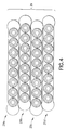
- the optical fiber ribbon embodiment illustrated in FIG. 1 can be arranged in a stack 29 . Because the hinge sections 26a, 26b have circular cross sections in each of the optical fiber ribbons 29a-29d of the stack, the optical fiber ribbons may rest in an alternating offset manner to each other.
- the ribbons 29a-29d may be bonded to each other with an adhesive (not shown) which is placed on the surface of the hinged sections where such ribbons make contact with each other.
- a lubricant such as silicone oil, may be applied to the surface of one or more of the ribbons to reduce adhesion between the ribbons 29a-29d , if desired.
- FIG. 5 An alternative embodiment of the optical fiber ribbon of the present invention is illustrated in FIG. 5.
- the hinged sections 32a, 32b are chevron shaped. Each has an outwardly pointed ridge section 34a, 34b forming a surface portion 36a, 36b which extends outwardly beyond the plane defined by the second substantially planar surface section 22b of the matrix material coating 20 .
- the chevron shaped hinge sections 32a, 32b also have inwardly pointed channel sections 38a, 38b which provides surface portions residing between the planes defined by the substantially planar surface sections 22a, 22b of the matrix material coating 20 .
- chevron shaped hinge sections 32a, 32b are illustrated as having the ridge sections 34a, 34b extending beyond the plane defined by second planar surface section 22b in the direction of normal N 2 , those skilled in the art will appreciate that one of the chevron shaped hinged sections may be formed so that its ridge section extends beyond the plane defined by the first planar surface section 22a in the direction of normal N 1 .
- a plurality of the optical fiber ribbon illustrated in FIG. 5 can be arranged in a stack 40 .
- the outwardly pointed ridge section of ribbon 40a resides in the channel section of ribbon 40b .
- the chevron shape of the hinge portion of the optical fiber ribbon prevents lateral movement of the optical fiber ribbons 40a-40d relative to each other.
- Adhesive may be applied to any surface of the optical fiber ribbon matrix, including the hinged sections, to bond the ribbons 40a-40d to form the stack 40 , if desired.
- a lubricant may be applied to the surface of one or more ribbons 40a-40d of the stack to reduce adhesion between such ribbons.
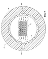
- a high count optical fiber cable in which the optical fibers can be easily accessed without special tools can be formed by disposing an optical fiber ribbon stack, such as 40 , formed with the optical fiber ribbon 10 of the present invention within a buffer tube 44 and circumscribing the buffer tube 44 with an outer jacket 46.
- Strength members 48a, 48b may be provided in the jacket 46 if desired. While not shown, armoring, water blocking compounds, ripcords and radial strength yarns may also be incorporated to cable in the typical fashion.
Landscapes
- Physics & Mathematics (AREA)
- General Physics & Mathematics (AREA)
- Optics & Photonics (AREA)
- Light Guides In General And Applications Therefor (AREA)
Applications Claiming Priority (2)
| Application Number | Priority Date | Filing Date | Title |
|---|---|---|---|
| US71641 | 1998-05-01 | ||
| US09/071,641 US6097866A (en) | 1998-05-01 | 1998-05-01 | Optical fiber ribbon |
Publications (1)
| Publication Number | Publication Date |
|---|---|
| EP0953858A1 true EP0953858A1 (de) | 1999-11-03 |
Family
ID=22102634
Family Applications (1)
| Application Number | Title | Priority Date | Filing Date |
|---|---|---|---|
| EP99400981A Withdrawn EP0953858A1 (de) | 1998-05-01 | 1999-04-22 | Faseroptische Bandleitung und faseroptisches Bandkabel |
Country Status (2)
| Country | Link |
|---|---|
| US (1) | US6097866A (de) |
| EP (1) | EP0953858A1 (de) |
Cited By (2)
| Publication number | Priority date | Publication date | Assignee | Title |
|---|---|---|---|---|
| US6097866A (en) * | 1998-05-01 | 2000-08-01 | Alcatel | Optical fiber ribbon |
| DE102006028727A1 (de) * | 2006-06-20 | 2008-01-10 | Yazaki Europe Ltd., Hemel Hempstead | Flachbandkabel |
Families Citing this family (15)
| Publication number | Priority date | Publication date | Assignee | Title |
|---|---|---|---|---|
| US6449412B1 (en) | 1998-06-30 | 2002-09-10 | Corning Cable Systems Llc | Fiber optic ribbon interconnect cable |
| US6317543B1 (en) * | 1999-11-19 | 2001-11-13 | Lucent Technologies Inc. | Cable with lubricated optical fibers and process of lubricating optical fibers |
| US6577797B2 (en) * | 2001-05-09 | 2003-06-10 | Hon Hai Precision Ind. Co., Ltd. | Optical fiber ribbon assembly with strain relief |
| US6678449B2 (en) | 2001-07-10 | 2004-01-13 | Alcatel | Visibly distinguishable colored optical fiber ribbons |
| US6792184B2 (en) | 2002-05-31 | 2004-09-14 | Corning Cable Systems Llc | Optical fiber ribbons having a preferential separation sequence |
| US6748148B2 (en) | 2002-05-31 | 2004-06-08 | Corning Cable Systems Llc | Optical fiber ribbons having a non-uniform thickness and/or preferential tear portions |
| US6853783B2 (en) | 2003-02-28 | 2005-02-08 | Corning Cable Systems Llc | Optical Fiber Ribbons Having Preferential Tear Portions |
| US7050688B2 (en) * | 2003-07-18 | 2006-05-23 | Corning Cable Systems Llc | Fiber optic articles, assemblies, and cables having optical waveguides |
| US7039282B2 (en) * | 2004-06-30 | 2006-05-02 | Corning Cable Systems Llc | Optical fiber array with an intermittent profile and method for manufacturing the same |
| US7274846B1 (en) | 2006-09-29 | 2007-09-25 | Corning Cable Systems, Llc. | Fiber optic ribbon subunits having ends with different shapes |
| US7532796B2 (en) * | 2006-09-29 | 2009-05-12 | Corning Cable Systems Llc | Fiber optic ribbons having one or more predetermined fracture regions |
| JP2008090040A (ja) * | 2006-10-03 | 2008-04-17 | Furukawa Electric Co Ltd:The | 光ファイバテープ心線 |
| US8989543B2 (en) * | 2011-11-17 | 2015-03-24 | Sumitomo Electric Industries, Ltd. | Optical cable |
| US11567283B2 (en) * | 2019-02-11 | 2023-01-31 | Sterlite Technologies Limited | Optical fibre ribbon and optical fibre cables thereof |
| JP7816160B2 (ja) * | 2020-10-19 | 2026-02-18 | 住友電気工業株式会社 | 光ファイバテープ心線 |
Citations (5)
| Publication number | Priority date | Publication date | Assignee | Title |
|---|---|---|---|---|
| US4900126A (en) * | 1988-06-30 | 1990-02-13 | American Telephone & Telegraph Co. | Bonded array of transmission media |
| US5212756A (en) * | 1992-01-21 | 1993-05-18 | Siecor Corporation | Fiber optic ribbon cable including flexible web |
| EP0647866A1 (de) * | 1993-10-12 | 1995-04-12 | ALCATEL CAVI S.p.A. | In mehrere Einheiten aufteilbarer optischer Fiberbandmodul, Verfahren zu seiner Herstellung und denselben benutzendes Kabel |
| EP0749129A1 (de) * | 1995-06-14 | 1996-12-18 | Schneider Electric Sa | Flachkabel und Entmantelungszange |
| EP0813084A1 (de) * | 1996-06-12 | 1997-12-17 | Alcatel | Druckkonzentration in einem optischen Faserband zum Erleichtern der Trennung des Band-Matrixmaterials |
Family Cites Families (14)
| Publication number | Priority date | Publication date | Assignee | Title |
|---|---|---|---|---|
| US2528667A (en) * | 1946-01-19 | 1950-11-07 | American Phenolic Corp | Loop antenna |
| GB1422147A (en) * | 1972-06-06 | 1976-01-21 | Bicc Ltd | Optical guides |
| FR2432721A1 (fr) * | 1978-07-31 | 1980-02-29 | Silec Liaisons Elec | Element de cablage pour fibres optiques |
| GB8605016D0 (en) * | 1986-02-28 | 1986-04-09 | Bicc Plc | Optical cable |
| GB2215084A (en) * | 1988-02-23 | 1989-09-13 | Stc Plc | Optical fibre ribbon containing cables |
| US4847443A (en) * | 1988-06-23 | 1989-07-11 | Amphenol Corporation | Round transmission line cable |
| US5166998A (en) * | 1992-02-21 | 1992-11-24 | Siecor Corporation | Optical ribbon cable component |
| GB2271859B (en) * | 1992-10-21 | 1995-10-18 | Northern Telecom Ltd | Optical fibre cable comprising stack of ribbon fibre elements |
| US5460683A (en) * | 1994-08-19 | 1995-10-24 | Sumitomo Electric Lightwave Corp. | Method for midspan entry of optical ribbon fiber |
| US5561730A (en) * | 1995-02-23 | 1996-10-01 | Siecor Corporation | Cable containing fiber ribbons with optimized frictional properties |
| US5673352A (en) * | 1996-01-12 | 1997-09-30 | Alcatel Submarine Networks, Inc. | Fiber optic micro cable |
| JPH09243884A (ja) * | 1996-03-12 | 1997-09-19 | Nippon Telegr & Teleph Corp <Ntt> | 光フラットケーブル |
| US5643393A (en) * | 1996-07-25 | 1997-07-01 | Siecor Corporation | Method for accessing optical ribbon fibers in midspan |
| US6097866A (en) * | 1998-05-01 | 2000-08-01 | Alcatel | Optical fiber ribbon |
-
1998
- 1998-05-01 US US09/071,641 patent/US6097866A/en not_active Expired - Lifetime
-
1999
- 1999-04-22 EP EP99400981A patent/EP0953858A1/de not_active Withdrawn
Patent Citations (5)
| Publication number | Priority date | Publication date | Assignee | Title |
|---|---|---|---|---|
| US4900126A (en) * | 1988-06-30 | 1990-02-13 | American Telephone & Telegraph Co. | Bonded array of transmission media |
| US5212756A (en) * | 1992-01-21 | 1993-05-18 | Siecor Corporation | Fiber optic ribbon cable including flexible web |
| EP0647866A1 (de) * | 1993-10-12 | 1995-04-12 | ALCATEL CAVI S.p.A. | In mehrere Einheiten aufteilbarer optischer Fiberbandmodul, Verfahren zu seiner Herstellung und denselben benutzendes Kabel |
| EP0749129A1 (de) * | 1995-06-14 | 1996-12-18 | Schneider Electric Sa | Flachkabel und Entmantelungszange |
| EP0813084A1 (de) * | 1996-06-12 | 1997-12-17 | Alcatel | Druckkonzentration in einem optischen Faserband zum Erleichtern der Trennung des Band-Matrixmaterials |
Cited By (2)
| Publication number | Priority date | Publication date | Assignee | Title |
|---|---|---|---|---|
| US6097866A (en) * | 1998-05-01 | 2000-08-01 | Alcatel | Optical fiber ribbon |
| DE102006028727A1 (de) * | 2006-06-20 | 2008-01-10 | Yazaki Europe Ltd., Hemel Hempstead | Flachbandkabel |
Also Published As
| Publication number | Publication date |
|---|---|
| US6097866A (en) | 2000-08-01 |
Similar Documents
| Publication | Publication Date | Title |
|---|---|---|
| US6097866A (en) | Optical fiber ribbon | |
| EP0262340B2 (de) | Optisches Bandkabel mit mehreren Elementen | |
| US5970196A (en) | Fiber optic protective member with removable section to facilitate separation thereof | |
| CN100430767C (zh) | 具有优先分离顺序的光纤带 | |
| US4900126A (en) | Bonded array of transmission media | |
| US8363994B2 (en) | Fiber optic cable assembly | |
| CN101889229B (zh) | 易分裂的光导纤维带 | |
| WO2008042171A2 (en) | Fiber optic ribbons having one or more predetermined fracture regions | |
| KR19990022203A (ko) | 섬유 광학 리본 케이블 및 이의 제조 방법 | |
| CN100468112C (zh) | 具有非均匀厚度和/或偏向拉扯部分的光纤带 | |
| US6853783B2 (en) | Optical Fiber Ribbons Having Preferential Tear Portions | |
| US5166998A (en) | Optical ribbon cable component | |
| US5643393A (en) | Method for accessing optical ribbon fibers in midspan | |
| CN110140072A (zh) | 高密度、低弯曲损耗光纤带电缆 | |
| US20020197033A1 (en) | Separable optical fiber ribbon having a tape with a preferential splitting direction and associated methods of fabricating and splitting the optical fiber ribbon | |
| JPH01150106A (ja) | テープ状光ファイバ心線 | |
| EP4556977A1 (de) | Glasfaserband und optisches kabel | |
| US7274846B1 (en) | Fiber optic ribbon subunits having ends with different shapes | |
| JPH0749447Y2 (ja) | 光フアイバテ−プ心線 | |
| JPH10148741A (ja) | 光ファイバリボン | |
| JP2003262770A (ja) | 光ファイバテープ心線 | |
| JP2774626B2 (ja) | テープ状光ファイバ心線 | |
| JPH04245209A (ja) | 高密度光ファイバケーブル |
Legal Events
| Date | Code | Title | Description |
|---|---|---|---|
| PUAI | Public reference made under article 153(3) epc to a published international application that has entered the european phase |
Free format text: ORIGINAL CODE: 0009012 |
|
| AK | Designated contracting states |
Kind code of ref document: A1 Designated state(s): DE ES FR GB IT |
|
| AX | Request for extension of the european patent |
Free format text: AL;LT;LV;MK;RO;SI |
|
| RIN1 | Information on inventor provided before grant (corrected) |
Inventor name: ROBINSON, RICHARD T. Inventor name: HINSON, ALFRED L. Inventor name: YANG, HOUCHING M. |
|
| 17P | Request for examination filed |
Effective date: 20000503 |
|
| AKX | Designation fees paid |
Free format text: DE ES FR GB IT |
|
| STAA | Information on the status of an ep patent application or granted ep patent |
Free format text: STATUS: THE APPLICATION IS DEEMED TO BE WITHDRAWN |
|
| 18D | Application deemed to be withdrawn |
Effective date: 20021031 |