EP4557071A2 - Informationsverarbeitungsvorrichtung, informationsverarbeitungsverfahren und programm - Google Patents
Informationsverarbeitungsvorrichtung, informationsverarbeitungsverfahren und programm Download PDFInfo
- Publication number
- EP4557071A2 EP4557071A2 EP25164033.0A EP25164033A EP4557071A2 EP 4557071 A2 EP4557071 A2 EP 4557071A2 EP 25164033 A EP25164033 A EP 25164033A EP 4557071 A2 EP4557071 A2 EP 4557071A2
- Authority
- EP
- European Patent Office
- Prior art keywords
- slider
- contact
- edge value
- value
- control unit
- Prior art date
- Legal status (The legal status is an assumption and is not a legal conclusion. Google has not performed a legal analysis and makes no representation as to the accuracy of the status listed.)
- Pending
Links
Images





Classifications
-
- G—PHYSICS
- G06—COMPUTING OR CALCULATING; COUNTING
- G06F—ELECTRIC DIGITAL DATA PROCESSING
- G06F3/00—Input arrangements for transferring data to be processed into a form capable of being handled by the computer; Output arrangements for transferring data from processing unit to output unit, e.g. interface arrangements
- G06F3/01—Input arrangements or combined input and output arrangements for interaction between user and computer
- G06F3/048—Interaction techniques based on graphical user interfaces [GUI]
- G06F3/0484—Interaction techniques based on graphical user interfaces [GUI] for the control of specific functions or operations, e.g. selecting or manipulating an object, an image or a displayed text element, setting a parameter value or selecting a range
- G06F3/04847—Interaction techniques to control parameter settings, e.g. interaction with sliders or dials
-
- G—PHYSICS
- G06—COMPUTING OR CALCULATING; COUNTING
- G06F—ELECTRIC DIGITAL DATA PROCESSING
- G06F3/00—Input arrangements for transferring data to be processed into a form capable of being handled by the computer; Output arrangements for transferring data from processing unit to output unit, e.g. interface arrangements
- G06F3/01—Input arrangements or combined input and output arrangements for interaction between user and computer
- G06F3/048—Interaction techniques based on graphical user interfaces [GUI]
- G06F3/0484—Interaction techniques based on graphical user interfaces [GUI] for the control of specific functions or operations, e.g. selecting or manipulating an object, an image or a displayed text element, setting a parameter value or selecting a range
- G06F3/0485—Scrolling or panning
- G06F3/04855—Interaction with scrollbars
-
- G—PHYSICS
- G06—COMPUTING OR CALCULATING; COUNTING
- G06F—ELECTRIC DIGITAL DATA PROCESSING
- G06F3/00—Input arrangements for transferring data to be processed into a form capable of being handled by the computer; Output arrangements for transferring data from processing unit to output unit, e.g. interface arrangements
- G06F3/01—Input arrangements or combined input and output arrangements for interaction between user and computer
- G06F3/048—Interaction techniques based on graphical user interfaces [GUI]
- G06F3/0487—Interaction techniques based on graphical user interfaces [GUI] using specific features provided by the input device, e.g. functions controlled by the rotation of a mouse with dual sensing arrangements, or of the nature of the input device, e.g. tap gestures based on pressure sensed by a digitiser
- G06F3/0488—Interaction techniques based on graphical user interfaces [GUI] using specific features provided by the input device, e.g. functions controlled by the rotation of a mouse with dual sensing arrangements, or of the nature of the input device, e.g. tap gestures based on pressure sensed by a digitiser using a touch-screen or digitiser, e.g. input of commands through traced gestures
Definitions
- the present invention relates to a field of information processing apparatus, information processing methods, and a program.
- a mobile information terminal using a slider is disclosed by, for example, Japanese Patent Application Laid-Open No. 2006-351042 .
- the slider displayed in a mobile information terminal using a touch screen in related art is arranged in a limited screen area for the mobile terminal.
- a pointing device such as a mouse
- the ratio of a slider length in the PC screen to the mouse pointer is relatively high, making the operation thereof easier.
- the slider displayed in a touch screen is operated by a finger
- the ratio of the slider length in the screen to the breadth of the tapping finger is frequently low.
- a thumb of the slider can be moved only by dragging, for example, it is difficult to perform a fine operation such as setting 120-min video content forward by 15 seconds.
- a fine operation such as setting 120-min video content forward by 15 seconds.
- an electrostatic touch panel it is difficult to accurately obtain pointing information indicating the position selected by the finger because noise is carried by electrostatic information, making fine seeks a very difficult operation.
- the present invention has been made in view of the above issue and it is desirable to provide a novel and improved technology capable of directly specifying the position of a slider displayed in a touch panel and easily adjusting the specified position.
- an information processing apparatus including a touch panel having a contact surface that can come into contact with an operating body and capable of acquiring position information indicating a contact position on the contact surface with the operating body and displaying information, a contact state quantity acquisition unit that acquires a contact state quantity indicating a contact state of the touch panel with the operating body, a storage unit that stores a start edge value of a specifiable range, which is a set of specifiable values that can be specified by the operating body, and an end edge value of the specifiable range and a display control unit that causes the touch panel to display a slider to specify one of the specifiable values by the operating body as a specified value and the start edge value and the end edge value stored in the storage unit and if the touch panel acquires position information indicating the position on the slider, decides a value corresponding to the position information as the specified value and also decides an interval to decide a new specifiable range in accordance with the contact state quantity acquired by the contact state
- the contact state quantity acquisition unit may include a contact time measuring unit that measures a contact time indicating a time in which the operating body continues to be in contact with an identical position of the touch panel up to a present time and acquires the contact time as the contact state quantity.
- the contact state quantity acquisition unit may include a contact area measuring unit that measures a contact area of the touch panel with the operating body and acquires the contact area as the contact state quantity.
- the contact state quantity acquisition unit may include a contact area measuring unit that measures a contact area of the touch panel with the operating body and an area increase calculation unit that calculates an area increase, which is an increase of the contact area measured by the contact area measuring unit, in a predetermined time up to a present time and acquires the area increase as the contact state quantity.
- the contact state quantity acquisition unit may include a pressure measuring unit that measures a magnitude of pressure exerted on the touch panel by the operating body and acquires the magnitude of the pressure as the contact state quantity.
- the contact state quantity acquisition unit may include a pressure measuring unit that measures a magnitude of pressure exerted on the touch panel by the operating body and a pressure increase calculation unit that calculates a pressure increase, which is an increase in magnitude of the pressure measured by the pressure measuring unit, in a predetermined time up to a present time and acquires the pressure increase as the contact state quantity.
- the storage unit may further store a threshold and the display control unit may determine whether the contact state quantity acquired by the contact state quantity acquisition unit exceeds the threshold stored in the storage unit and, if it is determined that the contact state quantity does not exceed the threshold, omits processing to decide an interval to decide a new specifiable range, processing to specify the new specifiable range based on the interval using the specified value as a reference, and processing to update the start edge value stored in the storage unit with the start edge value of the new specifiable range and also update the end edge value stored in the storage unit with the end edge value of the new specifiable range.
- the contact state quantity acquisition unit may further include a contact time measuring unit that measures a contact time indicating a time in which the operating body continues to be in contact with an identical position of the touch panel up to a present time and acquires the contact time as the contact state quantity and the display control unit may determine whether the contact time acquired by the contact time measuring unit exceeds the threshold stored in the storage unit and, if it is determined that the contact time does not exceed the threshold, further determines whether the touch panel has acquired other position information than the position information indicating the position on the slider and, if the other position information has been acquired, does not omit processing to decide the interval to decide the new specifiable range, processing to specify the new specifiable range based on the interval using the specified value as a reference, and processing to update the start edge value stored in the storage unit with the start edge value of the new specifiable range and also update the end edge value stored in the storage unit with the end edge value of the new specifiable range.
- a contact time measuring unit that measures a contact time indicating a
- the display control unit may calculate an output value by accepting the contact state quantity acquired by the contact state quantity acquisition unit as an input value based on a predetermined calculation formula and decides the output value as an interval to decide the new specifiable range.
- the storage unit may further store a constant to decide the interval and the display control unit may decide a value obtained by dividing a value obtained by subtracting the end edge value from the start edge value stored in the storage unit by the constant stored in the storage unit as the interval.
- the display control unit may acquire the start edge value by subtracting a value half the interval from the specified value and also acquires the end edge value by adding the value half the interval to the specified value to specify the new specifiable range using the start edge value and the end edge value.
- the display control unit when the touch panel acquires the position information indicating the position of a start edge of the slider after the start edge value and the end edge value stored in the storage unit being updated, may update the start edge value stored in the storage unit with a new start edge value by obtaining the new start edge value by subtracting a scroll value, which is a value in accordance with the interval, from the start edge value stored in the storage unit and also may update the end edge value stored in the storage unit with a new end edge value by obtaining the new end edge value by subtracting the scroll value from the end edge value stored in the storage unit and may cause the touch panel to display the start edge value and the end edge value stored in the storage unit.
- a scroll value which is a value in accordance with the interval
- the information processing apparatus may further include a processing unit that performs processing in accordance with the position information indicating the position on the slider acquired by the touch panel.
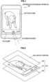
- FIG. 1 is a diagram showing a usage example of an information processing apparatus according to the first embodiment of the present invention.
- a usage example of the information processing apparatus according to the first embodiment of the present invention will be described using FIG. 1 .
- an information processing apparatus 100 (such as a mobile device) provided with a touch panel 103 on the front side will be described.
- a user directly selects the position on a slider 101a displayed in the touch panel 103.
- the user uses, for example, an operating body 210 for a tap operation in the touch panel 103.
- a forefinger of the right hand of the user is used as the operating body 210, but the operating body 210 is not limited to the forefinger of the right hand and any finger that is easy for the user to use may be used.
- a finger of the left hand may be used or another finger (a thumb, middle finger, fourth finger, or little finger) may be used.
- FIG. 2 is an exploded perspective view showing the hardware configuration of an information processing apparatus according to the first embodiment of the present invention.
- the hardware configuration of the information processing apparatus according to the first embodiment of the present invention will be described below using FIG. 2 (FIG. 1 is also referenced when appropriate).
- the information processing apparatus 100 according to the first embodiment should be distinguished from the information processing apparatus 100 according to other embodiments, the information processing apparatus will be denoted as an information processing apparatus 100a. If there is no need to distinguish the information processing apparatus 100, the information processing apparatus will be denoted as the information processing apparatus 100.
- an information input apparatus 102 is placed on the top surface of the information processing apparatus 100a.
- the information input apparatus 102 has a contact surface 102a capable of coming into contact with the operating body 210 of the user and can acquire position information indicating the contact position with the operating body 210 on the contact surface 102a.
- the information input apparatus 102 outputs the acquired position information to a CPU 108 as an information signal.
- the user of the information processing apparatus 100a can input various kinds of data into the information processing apparatus 100a or provide instructions of processing operation by operating the information input apparatus 102 through the operating body 210.
- the information input apparatus 102 forms a portion of the touch panel 103. In the first embodiment, any type of touch panel capable of obtaining position information indicating the contact position with the operating body 210 on the contact surface 102a may be used as the touch panel 103.
- a display device 101 is placed below the information input apparatus 102.
- the display device 101 is enabled to display information.
- the display device 101 forms a portion of the touch panel 103.
- the display device 101 is configured of an apparatus capable of visually notifying the user of information such as an LCD (Liquid Crystal Display) and organic EL (Electroluminescence) display device.
- the display device 101 outputs, for example, results obtained by various kinds of processing performed by the information processing apparatus 100a. More specifically, the display device 101 displays results obtained by various kinds of processing performed by the information processing apparatus 100a by text or images.
- a base 109 is placed below the display device 101.
- Various components or devices used by the information processing apparatus 100a are mounted on the base 109. More specifically, devices such as a non-volatile memory 106, a RAM (Random Access Memory) 107, a CPU (Central Processing Unit) 108 and the like described using FIG. 3 later are mounted.
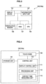
- FIG. 3 is a block diagram showing the hardware configuration of the information processing apparatus according to the first embodiment of the present invention.
- the hardware configuration of the information processing apparatus according to the first embodiment of the present invention will be described below using FIG. 3 ( FIG. 1 and FIG. 2 are also referenced when appropriate).
- the information processing apparatus 100a includes the touch panel 103 (the display device 101 and the information input apparatus 102), the non-volatile memory 106, the RAM 107, and the CPU 108.
- the non-volatile memory (storage unit) 106 is a data storage apparatus formed as an example of the storage unit of the information processing apparatus 100a and is configured of, for example, a magnetic storage device such as an HDD (Hard Disk Drive), semiconductor storage device, optical storage device, or magneto-optical storage device.
- the non-volatile memory 106 stores programs executed by the CPU 108 and various kinds of data.
- the RAM 107 temporarily stores programs used by the CPU 108 and parameters that appropriately change during execution thereof.
- the CPU 108 functions as an arithmetic processing unit and a control apparatus and controls the overall operation inside the information processing apparatus 100 or a portion thereof according to various programs recorded in the non-volatile memory 106 or the RAM 107.
- the CPU 108 is formed as a portion of the control unit of the information processing apparatus 100a.
- FIG. 4 is a functional block diagram of the information processing apparatus according to the first embodiment of the present invention. The function of the information processing apparatus according to the first embodiment of the present invention will be described below using FIG. 4 ( FIG. 1 to FIG. 3 are also referenced when appropriate).
- the information processing apparatus 100a includes the touch panel 103, a control unit 110, and a storage unit 120.
- the control unit 110 is configured of a display control unit 111 and a processing unit 112.
- the display control unit 111 will be described later with reference to FIG. 5 .
- the control unit 110 is provided with a contact state quantity acquisition unit (for example, a contact time measuring unit 113) for acquiring a contact state quantity indicating a contact state of the operating body 210 and the touch panel 103.
- the touch panel 103 has the contact surface 102a capable of coming into contact with the operating body 210 so that position information indicating the contact position with the operating body 210 on the contact surface 102a can be obtained and also information can be displayed.
- the contact state quantity acquisition unit (for example, the contact time measuring unit 113) included in the control unit 110 is provided with the contact time measuring unit 113 that measures a contact time indicating a time interval in which the operating body 210 has been in contact with the same position of the touch panel 103 up to the present time and acquires the contact time as a contact state quantity.
- the storage unit 120 stores a start edge value of a specifiable range, which is a set of specifiable values that can be specified by the operating body 210, and an end edge value of the specifiable range.
- the start edge value is, for example, the minimum value of the specifiable range and the end edge value is, for example, the maximum value of the specifiable range.
- the start edge value and the end edge value are not limited to the above example, the start edge value may be the maximum value of the specifiable range, and the end edge value may be the minimum value of the specifiable range.
- the processing unit 112 performs processing in accordance with position information indicating the position on a slider acquired by the touch panel 103.
- Processing in accordance with position information is not specifically limited and if the storage unit 120 stores content data, processing may be to adjust the reproduction position of the content data stored by the storage unit 120 to the value corresponding to position information acquired by the touch panel 103.
- processing in accordance with position information is not limited to processing to adjust the reproduction position of content data and if, for example, content data is audio data, may be processing to adjust the output value (such as an output volume) when the content data is reproduced to the value corresponding to position information.
- FIG. 5 is a diagram showing a screen display example by a display control unit of the information processing apparatus according to the first embodiment of the present invention.
- a screen display example by the display control unit of the information processing apparatus according to the first embodiment of the present invention will be described below using FIG. 5 ( FIG. 1 to FIG. 4 are also referenced when appropriate).
- FIG. 5 shows the slider 101a displayed by the display control unit 111 in the touch panel 103.
- the slider 101a is assumed to correspond to at least a specifiable range displayed in the touch panel 103.
- a thumb 101b is displayed on the slider 101a at the position corresponding to the specified value currently specified.
- a start edge value 101c is the minimum value of the specifiable range and an end edge value 101f is the maximum value of the specifiable range.
- FIG. 5 also shows a zoom slider 101i displayed by the display control unit 111 in the touch panel 103.
- the zoom slider 101i is displayed at the position corresponding to the aforementioned new specifiable range.
- a start edge value 101d of the zoom slider 101i is the minimum value of the new specifiable range and an end edge value 101e of the zoom slider 101i is the maximum value of the new specifiable range.
- the thumb 101b displayed on the slider 101a also serves as a thumb displayed on the zoom slider 101i. If no operation is performed by the operating body 210, the start edge value 101d and the end edge value 101e of the zoom slider 101i are the same as values corresponding to the thumb 101b and the zoom slider 101i is not displayed.
- An interval start edge value 101g shows the start edge value of an interval to decide a new specifiable range and is denoted here as "0:00".
- An interval end edge value 101h shows the end edge value of an interval to decide a new specifiable range and is denoted here as "24:00".
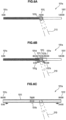
- FIG. 6 is an explanatory view (Part 1) illustrating the function of the display control unit of the information processing apparatus according to the first embodiment of the present invention.
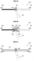
- FIG. 7 is an explanatory view (Part 2) illustrating the function of the display control unit of the information processing apparatus according to the first embodiment of the present invention.
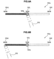
- FIG. 8 is an explanatory view (Part 3) illustrating the function of the display control unit of the information processing apparatus according to the first embodiment of the present invention.
- the function of the display control unit of the information processing apparatus according to the first embodiment of the present invention will be described below using FIG. 6 to FIG. 8 ( FIG. 1 to FIG. 5 are also referenced when appropriate).
- FIG. 6A shows the slider 101a displayed when the touch panel 103 acquires position information.
- the display control unit 111 causes the touch panel 103 to display the slider 101a to specify one of specifiable values as the specified value through the operating body 210 and the start edge value 101c and the end edge value 101f stored in the storage unit 120.
- the thumb 101b may be displayed on the slider 101a at the position corresponding to the specified value currently specified.
- the display control unit 111 may cause the touch panel 103 to display a specified value 101j currently specified near the thumb 101b.
- the display control unit 111 decides the value corresponding to the acquired position information as the specified value.
- the display control unit 111 is enabled to determine one specifiable value corresponding to the position information and decides the determined specifiable value as the specified value.
- the position on the slider 101a corresponding to the reproduction time 78 min of content data whose reproduction time 120 min is first tapped by the operating body 210.
- the display control unit 111 decides the specified value and also decides an interval to decide a new specifiable range in accordance with a contact state quantity acquired by the contact state quantity acquisition unit (for example, the contact time measuring unit 113).
- the contact time measuring unit 113 measures a contact time indicating a time in which the operating body 210 has been in contact with the same position of the touch panel 103 up to the present time and acquires the contact time as a contact state quantity.
- the storage unit 120 may further store a threshold so that the display control unit 111 determines whether a contact state quantity acquired by the contact state quantity acquisition unit (for example, the contact time measuring unit 113) exceeds the threshold stored in the storage unit 120. In this manner, the display control unit 111 may decide an interval to decide a new specifiable range only if the display control unit 111 determines that a contact state quantity exceeds the threshold. That is, if the display control unit 111 determines that a contact state quantity does not exceed the threshold, the display control unit 111 may omit processing to decide an interval to decide a new specifiable range. The display control unit 111 may further omit processing to specify a new specifiable range by an interval using a specified value as a reference.
- the display control unit 111 may further omit processing to update the start edge value stored in the storage unit 120 with a start edge value of a new specifiable range and the end edge value stored in the storage unit 120 with an end edge value of the new specifiable range.
- the display control unit 111 determines whether the contact time acquired by the contact time measuring unit 113 exceeds a threshold stored in the storage unit 120. If the display control unit 111 determines that the contact time does not exceed the threshold, the display control unit 111 may further determine whether the touch panel 103 has acquired other position information than the position information indicating the position on the slider 101a. If the display control unit 111 determines that other position information has been acquired, the display control unit 111 may perform processing to decide an interval to decide a new specifiable range without omitting the processing. In this case, the display control unit 111 may perform processing to specify a new specifiable range by an interval using a specified value as a reference without omitting the processing.
- the display control unit 111 may perform processing to update the start edge value stored in the storage unit with a start edge value of a new specifiable range and the end edge value stored in the storage unit with an end edge value of the new specifiable range without omitting the processing.
- the contact time measuring unit 113 determines whether the measured contact time exceeds the threshold (for example, 2 sec).
- the magnitude of the threshold is not specifically limited and a threshold of magnitude easier to use for the user may be stored in the storage unit 120 in advance or any threshold may freely be set by the user.
- the display control unit 111 may calculate an output value based on a predetermined calculation formula by accepting a contact state quantity acquired by the contact state quantity acquisition unit (for example, the contact time measuring unit 113) as an input value to decide the output value as an interval to decide a new specifiable range.
- the predetermined calculation formula that outputs an interval after a contact state quantity being input is not specifically limited and may be, for example, a calculation formula representing a relationship in which the contact state quantity and the interval are proportional.
- the display control unit 111 specifies a new specifiable range based on the decided interval using the decided value as a reference.
- FIG. 6B shows the slider 101a displayed after a new specifiable range being decided the display control unit 111. As shown in FIG. 6B , the display control unit 111 may cause the touch panel 103 to display the zoom slider 101i.
- the storage unit 120 further stores a constant to decide an interval and the display control unit 111 can decide, for example, a value obtained by dividing a value obtained by subtracting an end edge value from a start edge value stored in the storage unit 120 by the constant stored in the storage unit 120 as an interval.
- FIG. 6B shows a case in which the constant stored in the storage unit 120 is "5", the start edge value stored in the storage unit 120 is "0:00", and the end edge value stored in the storage unit 120 is "120:00".
- the display control unit 111 may acquire a start edge value, for example, by subtracting a value half the decided interval from the decided specified value and an end edge value by adding the value half the decided interval to the decided specified value.
- the display control unit 111 can obtain the start edge value "66:00” by subtracting the value "24:00/2" half the decided interval from the decided specified value "78:00".
- the display control unit 111 can also obtain the end edge value "90:00” by adding the value "24:00/2" half the decided interval to the decided specified value "78:00".
- the display control unit 111 can specify a new specifiable range by the acquired start edge value and end edge value.
- the display control unit 111 updates the start edge value stored in the storage unit 120 with the start edge value of the new specifiable range and the end edge value stored in the storage unit 120 with the end edge value of the new specifiable range.
- the display control unit 111 causes the touch panel 103 to display the start edge value and the end edge value stored in the storage unit 120.
- FIG. 6C shows the slider 101a after being updated by the display control unit 111 with the specifiable range.
- the display control unit 111 can repeat the update of a specifiable range described above.
- FIG. 7A shows the slider 101a after the specified range is updated with a new specifiable range.
- the contact time measuring unit 113 determines whether the measured contact time exceeds the threshold. If the time measuring unit 113 determines that the measured contact time exceeds the threshold, the display control unit 111 decides the interval.
- the display control unit 111 can obtain the start edge value "75:36" by subtracting the value "4:48/2" half the decided interval from the decided specified value "78:00".
- the display control unit 111 can also obtain the end edge value "80:24” by adding the value "4:48/2" half the decided interval to the decided specified value "78:00".
- the display control unit 111 can specify a new specifiable range by the acquired start edge value and end edge value.
- FIG. 7B shows the slider 101a displayed when the display control unit 111 decides a new specifiable range.
- the display control unit 111 updates the start edge value stored in the storage unit 120 with the start edge value of the new specifiable range and the end edge value stored in the storage unit 120 with the end edge value of the new specifiable range.
- the display control unit 111 causes the touch panel 103 to display the start edge value and the end edge value stored in the storage unit 120.
- FIG. 7C shows the slider 101a after being updated by the display control unit 111 with the new specifiable range.
- the display control unit 111 can repeat the update of the specifiable range as described above until the maximum zoom rate is reached.
- the user can restore the default display of the slider 101a with the start edge value "0:00" and end edge value "120:00” by moving the operating body 210 off the touch panel 103 to cancel zooming of the slider 101a.
- FIG. 8A shows the slider 101a after the specified range is updated with a new specifiable range. That is, the slider 101a shown in FIG. 8A is the same as the slider 101a shown in FIG. 7A .
- the touch panel 103 acquires position information indicating the position of the start edge of the slider 101a in the state shown in FIG. 8A .
- the display control unit 111 may acquire a new start edge value by subtracting a scroll value, which is a value in accordance with an interval, from the start edge value stored in the storage unit 120 to update the start edge value stored in the storage unit 120 with the acquired new start edge value.
- the display control unit 111 may acquire a new end edge value by subtracting the scroll value from the end edge value stored in the storage unit 120 to update the end edge value stored in the storage unit 120 with the acquired new end edge value. Then, the display control unit 111 causes the touch panel 103 to display the start edge value and the end edge value stored in the storage unit 120. The start edge value and the end edge value of the slider 101a displayed at this point are scrolled in the direction in which the value decreases. FIG. 8B shows the slider 101a after being scrolled.
- the display control unit 111 may acquire a new start edge value by adding a scroll value, which is a value in accordance with an interval, to the start edge value stored in the storage unit 120 to update the start edge value stored in the storage unit 120 with the acquired new start edge value.
- the display control unit 111 may acquire a new end edge value by adding the scroll value to the end edge value stored in the storage unit 120 to update the end edge value stored in the storage unit 120 with the acquired new end edge value.
- the display control unit 111 causes the touch panel 103 to display the start edge value and the end edge value stored in the storage unit 120.
- the start edge value and the end edge value of the slider 101a displayed at this point are scrolled in the direction in which the value increases.
- FIG. 9 is a flow chart showing an operation of the information processing apparatus according to the first embodiment of the present invention. The operation of the information processing apparatus according to the first embodiment of the present invention will be described below using FIG. 9 ( FIG. 1 to FIG. 8 are also referenced when appropriate).
- the information processing apparatus 100 generates a thread that continues to monitor whether the screen is tapped when an application is activated.
- the display control unit 111 determines therein whether the slider 101a is tapped (step S101). If the display control unit 111 determines that the slider 101a is not tapped ("No" at step S101), the display control unit 111 cancels a zoom slider (step S102) before returning to step S101. If the display control unit 111 determines that the slider 101a is tapped ("Yes" at step S101), the display control unit 111 moves the thumb 101b to the tapped position (step S103) and the processing unit 112 performs processing in accordance with the tapped position.
- the display control unit 111 determines whether the operating body 210 continues to tap the same position for a predetermined time (step S104). If the display control unit 111 determines that the operating body 210 continues to tap the same position for a predetermined time ("Yes" at step S104), the display control unit 111 proceeds to step S106. If the display control unit 111 determines that the operating body 210 does not continue to tap the same position for a predetermined time ("No" at step S104), the display control unit 111 determines whether any other position is tapped while the slider 101a being tapped (step S105). If the display control unit 111 determines that no other position is tapped while the slider 101a being tapped (“No” at step S105), the display control unit 111 returns to step S101. If the display control unit 111 determines that another position is tapped while the slider 101a being tapped ("Yes" at step S105), the display control unit 111 proceeds to step S 106.
- step S106 the display control unit 111 performs processing to enlarge the slider 101a around the tap point to a predetermined interval. After the enlargement is finished, the display control unit 111 returns to step S101 to repeat the processing.
- the hardware configuration of an information processing apparatus according to the second embodiment of the present invention is similar to that of an information processing apparatus according to the first embodiment of the present invention. Therefore, the description of the hardware configuration of an information processing apparatus according to the second embodiment of the present invention is omitted.
- the information processing apparatus 100 according to the second embodiment should be distinguished from the information processing apparatus 100 according to other embodiments, the information processing apparatus will be denoted as an information processing apparatus 100b. If there is no need to distinguish the information processing apparatus 100, the information processing apparatus will be denoted as the information processing apparatus 100.
- FIG. 10 is a functional block diagram of the information processing apparatus according to the second embodiment of the present invention.
- the function of the information processing apparatus according to the second embodiment of the present invention will be described below using FIG. 10 ( FIG. 1 to FIG. 9 are also referenced when appropriate).
- FIG. 10 FIG. 1 to FIG. 9 are also referenced when appropriate.
- only blocks of the functional configuration of the information processing apparatus according to the second embodiment of the present invention that are different from those of the functional configuration of the information processing apparatus according to the first embodiment of the present invention will be described.
- the contact state quantity acquisition unit is provided with a contact area measuring unit 114 that measures a contact area of the touch panel 103 with the operating body 210 and acquires the contact area as a contact state quantity.
- a touch panel for example, an electrostatic touch panel
- the contact state quantity acquisition unit may further be provided with an area increase calculation unit 115 that calculates an area increase, which is an increase in contact area measured by the contact area measuring unit 114, in a predetermined time up to the present time and acquires the area increase as a contact state quantity.
- the predetermined time up to the present time may be a time interval between a time that goes back the predetermined time from the present time and the present time or, if the operating body 210 continues to tap the touch panel 103, a time interval between the first tap time and the present time.
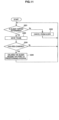
- FIG. 11 is a flow chart showing the operation of the information processing apparatus according to the second embodiment of the present invention. The operation of the information processing apparatus according to the second embodiment of the present invention will be described below using FIG. 11 ( FIG. 1 to FIG. 10 are also referenced when appropriate).
- the information processing apparatus 100 generates a thread that continues to monitor whether the screen is tapped when an application is activated.
- the display control unit 111 determines therein whether the slider 101a is tapped (step S201). If the display control unit 111 determines that the slider 101a is not tapped ("No" at step S201), the display control unit 111 cancels a zoom slider (step S202) before returning to step S201. If the display control unit 111 determines that the slider 101a is tapped ("Yes" at step S201), the display control unit 111 moves the thumb 101b to the tapped position (step S203) and the processing unit 112 performs processing in accordance with the tapped position.
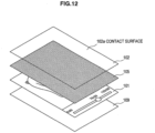
- FIG. 12 is an exploded perspective view showing the hardware configuration of the information processing apparatus according to the third embodiment of the present invention.
- the hardware configuration of the information processing apparatus according to the third embodiment of the present invention will be described below using FIG. 12 ( FIG. 1 is also referenced when appropriate).
- the information processing apparatus 100 according to the third embodiment should be distinguished from the information processing apparatus 100 according to other embodiments, the information processing apparatus will be denoted as an information processing apparatus 100c. If there is no need to distinguish the information processing apparatus 100, the information processing apparatus will be denoted as the information processing apparatus 100. Only differences from the hardware configuration of the information processing apparatus 100a according to the first embodiment will be described.
- a pressure sensor 105 is arranged below the information input apparatus 102 of the information processing apparatus 100c.
- the pressure sensor 105 may be arranged, as shown in FIG. 12 , over the entire surface below the information input apparatus 102 or set up at predetermined locations (for example, four corners), but the location where the pressure sensor 105 is arranged is not specifically limited.
- the pressure sensor 105 may be arranged at any location where pressure received by the contact surface 102a from the operating body 210 can be detected when the user presses the information input apparatus 102 through the operating body 210.
- FIG. 13 is a block diagram showing the hardware configuration of the information processing apparatus according to the third embodiment of the present invention.
- the hardware configuration of the information processing apparatus according to the third embodiment of the present invention will be described below using FIG. 13 ( FIG. 1 and FIG. 12 are also referenced when appropriate).
- the information processing apparatus 100c further includes the pressure sensor 105.
- the pressure sensor 105 can detect, as described above, pressure received by the contact surface 102a from the operating body 210 and the type thereof is not specifically limited.
- FIG. 14 is a functional block diagram of the information processing apparatus according to the third embodiment of the present invention.
- the function of the information processing apparatus according to the third embodiment of the present invention will be described below using FIG. 14 ( FIG. 1 to FIG. 13 are also referenced when appropriate).
- FIG. 14 FIG. 1 to FIG. 13 are also referenced when appropriate.
- blocks of the functional configuration of the information processing apparatus according to the third embodiment of the present invention that are different from those of the functional configuration of the information processing apparatus according to the first embodiment of the present invention will be described.
- the contact state quantity acquisition unit is provided with the pressure sensor 105 (pressure measuring unit) that measures the magnitude of pressure exerted on the touch panel 103 by the operating body 210 and acquires the magnitude of measured pressure as a contact state quantity.
- the contact state quantity acquisition unit may further be provided with a pressure increase calculation unit 116 that calculates a pressure increase, which is an increase in magnitude of pressure measured by the pressure sensor 105, in a predetermined time up to the present time and acquires the pressure increase as a contact state quantity.
- the predetermined time up to the present time may be a time interval between a time that goes back the predetermined time from the present time and the present time or, if the operating body 210 continues to tap the touch panel 103, a time interval between the first tap time and the present time.
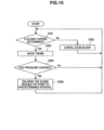
- FIG. 15 is a flow chart showing the operation of the information processing apparatus according to the third embodiment of the present invention. The operation of the information processing apparatus according to the third embodiment of the present invention will be described below using FIG. 15 ( FIG. 1 to FIG. 14 are also referenced when appropriate).
- the information processing apparatus 100 generates a thread that continues to monitor whether the screen is tapped when an application is activated.
- the display control unit 111 determines therein whether the slider 101a is tapped (step S301). If the display control unit 111 determines that the slider 101a is not tapped ("No" at step S301), the display control unit 111 cancels a zoom slider (step S302) before returning to step S301. If the display control unit 111 determines that the slider 101a is tapped ("Yes" at step S301), the display control unit 111 moves the thumb 101b to the tapped position (step S303) and the processing unit 112 performs processing in accordance with the tapped position.
- the display control unit 111 determines whether the pressure measured by the pressure sensor 105 has changed (step S304). If the display control unit 111 determines that the pressure has not changed ("No" at step S304), the display control unit 111 returns to step S101. If the display control unit 111 determines that the pressure has changed ("Yes" at step S304), the display control unit 111 performs processing to enlarge the slider 101a around the tap point to a predetermined interval (step S305). After the enlargement is finished, the display control unit 111 returns to step S301 to repeat the processing.
- the hardware configuration of an information processing apparatus according to the fourth embodiment of the present invention is similar to that of an information processing apparatus according to the first embodiment of the present invention. Therefore, the description of the hardware configuration of an information processing apparatus according to the fourth embodiment of the present invention is omitted.
- the information processing apparatus 100 according to the fourth embodiment should be distinguished from the information processing apparatus 100 according to other embodiments, the information processing apparatus will be denoted as an information processing apparatus 100d. If there is no need to distinguish the information processing apparatus 100, the information processing apparatus will be denoted as the information processing apparatus 100.
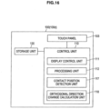
- FIG. 16 is a functional block diagram of the information processing apparatus according to the fourth embodiment of the present invention.
- the function of the information processing apparatus according to the fourth embodiment of the present invention will be described below using FIG. 16 ( FIG. 1 to FIG. 15 are also referenced when appropriate).
- FIG. 16 FIG. 1 to FIG. 15 are also referenced when appropriate.
- blocks of the functional configuration of the information processing apparatus according to the fourth embodiment of the present invention that are different from those of the functional configuration of the information processing apparatus according to the first embodiment of the present invention will be described.
- the contact state quantity acquisition unit is provided with a contact position detection unit 117 that detects the contact position on the touch panel 103 by the operating body 210 and acquires the detected contact position as a contact state quantity.
- the contact state quantity acquisition unit may further be provided with an orthogonal direction change calculation unit 118 that calculates an orthogonal direction change, which is a change of the contact position detected by the contact position detection unit 117 in a direction orthogonal to the slider 101a, in a predetermined time up to the present time and acquires the calculated orthogonal direction change as a contact state quantity.
- the predetermined time up to the present time may be a time interval between a time that goes back the predetermined time from the present time and the present time or, if the operating body 210 continues to tap the touch panel 103, a time interval between the first tap time and the present time.
- the direction (longitudinal direction) in which the slider 101a extends is the X-axis direction and a direction orthogonal to the X-axis direction is the Y-axis direction
- a change of coordinate (Y coordinate) in the Y-axis direction corresponds to a change in a direction orthogonal to the slider 101a.
- the display control unit 111 may decide an interval to decide a new specifiable range.
- the predetermined quantity is not specifically limited and may be set to, for example, the length of predetermined pixels (for example, the length corresponding to 30 pixels).
- the user taps the touch panel 103 by a tip portion (such as a fingertip) of the operating body 210 and then, taps the touch panel 103 by another portion (such as a finger cushion) of the operating body 210 by laying down the operating body 210.
- the orthogonal direction change calculation unit 118 can detect the change of the Y coordinate as a contact state quantity. Therefore, similar to the case in which a technique to measure the contact area is used by simple coordinate comparisons shown in the second embodiment, a contact state quantity of the touch panel 103 with the operating body 210 can be acquired.
- FIG. 17 is a flow chart showing the operation of the information processing apparatus according to the fourth embodiment of the present invention. The operation of the information processing apparatus according to the fourth embodiment of the present invention will be described below using FIG. 17 ( FIG. 1 to FIG. 16 are also referenced when appropriate).
- the information processing apparatus 100 generates a thread that continues to monitor whether the screen is tapped when an application is activated.
- the display control unit 111 determines therein whether the slider 101a is tapped (step S401). If the display control unit 111 determines that the slider 101a is not tapped ("No" at step S401), the display control unit 111 cancels a zoom slider (step S402) before returning to step S401. If the display control unit 111 determines that the slider 101a is tapped ("Yes" at step S401), the display control unit 111 moves the thumb 101b to the tapped position (step S403) and the processing unit 112 performs processing in accordance with the tapped position.
- the display control unit 111 determines whether a change of coordinate in a direction orthogonal to the slider axis of a portion being tapped by the operating body 210 has occurred (step S404). If the display control unit 111 determines that no change of coordinate in a direction orthogonal to the slider axis has occurred ("No" at step S404), the display control unit 111 returns to step S401. If the display control unit 111 determines that a change of coordinate in a direction orthogonal to the slider axis has occurred ("Yes" at step S404), the display control unit 111 performs processing to enlarge the slider 101a around the tap point to a predetermined interval (step S405). After the enlargement is finished, the display control unit 111 returns to step S401 to repeat the processing.
- the start point and end point of a slider can recursively be zoomed in around the position being tapped in accordance with a contact state quantity (such as the time during which the slider is tapped, a contact area of a tapping finger, pressure of a tapping finger, and a change of coordinate in a direction orthogonal to the slider axis) of a operating body with respect to the slider. Accordingly, fine pointing in seconds can be accomplished even if a drag operation of long-time content such as 120 min is performed in an apparatus in which an adequate screen area is not secured using a pointing interface with a wide setup area such as a finger. Moreover, accordingly, an operation enabling direct time designation, which is characteristic of a slider in related art, can be realized.
- the present application contains subject matter related to that disclosed in Japanese Priority Patent Application JP 2008-318573 filed in the Japan Patent Office on December 15, 2008 and Japanese Priority Patent Application JP 2009-175581 filed in the Japan Patent Office on July/28/2009 .
Landscapes
- Engineering & Computer Science (AREA)
- General Engineering & Computer Science (AREA)
- Theoretical Computer Science (AREA)
- Human Computer Interaction (AREA)
- Physics & Mathematics (AREA)
- General Physics & Mathematics (AREA)
- User Interface Of Digital Computer (AREA)
- Position Input By Displaying (AREA)
Applications Claiming Priority (4)
| Application Number | Priority Date | Filing Date | Title |
|---|---|---|---|
| JP2008318573 | 2008-12-15 | ||
| JP2009175581A JP2010165337A (ja) | 2008-12-15 | 2009-07-28 | 情報処理装置、情報処理方法およびプログラム |
| EP18213108.6A EP3483711A1 (de) | 2008-12-15 | 2009-11-10 | Informationsverarbeitungsvorrichtung, informationsverarbeitungsverfahren und programm |
| EP09252590.6A EP2196893A3 (de) | 2008-12-15 | 2009-11-10 | Informationsverarbeitungsvorrichtung, Informationsverarbeitungsverfahren und Programm |
Related Parent Applications (2)
| Application Number | Title | Priority Date | Filing Date |
|---|---|---|---|
| EP18213108.6A Division EP3483711A1 (de) | 2008-12-15 | 2009-11-10 | Informationsverarbeitungsvorrichtung, informationsverarbeitungsverfahren und programm |
| EP09252590.6A Division EP2196893A3 (de) | 2008-12-15 | 2009-11-10 | Informationsverarbeitungsvorrichtung, Informationsverarbeitungsverfahren und Programm |
Publications (2)
| Publication Number | Publication Date |
|---|---|
| EP4557071A2 true EP4557071A2 (de) | 2025-05-21 |
| EP4557071A3 EP4557071A3 (de) | 2025-07-16 |
Family
ID=41697875
Family Applications (3)
| Application Number | Title | Priority Date | Filing Date |
|---|---|---|---|
| EP25164033.0A Pending EP4557071A3 (de) | 2008-12-15 | 2009-11-10 | Informationsverarbeitungsvorrichtung, informationsverarbeitungsverfahren und programm |
| EP18213108.6A Ceased EP3483711A1 (de) | 2008-12-15 | 2009-11-10 | Informationsverarbeitungsvorrichtung, informationsverarbeitungsverfahren und programm |
| EP09252590.6A Withdrawn EP2196893A3 (de) | 2008-12-15 | 2009-11-10 | Informationsverarbeitungsvorrichtung, Informationsverarbeitungsverfahren und Programm |
Family Applications After (2)
| Application Number | Title | Priority Date | Filing Date |
|---|---|---|---|
| EP18213108.6A Ceased EP3483711A1 (de) | 2008-12-15 | 2009-11-10 | Informationsverarbeitungsvorrichtung, informationsverarbeitungsverfahren und programm |
| EP09252590.6A Withdrawn EP2196893A3 (de) | 2008-12-15 | 2009-11-10 | Informationsverarbeitungsvorrichtung, Informationsverarbeitungsverfahren und Programm |
Country Status (6)
| Country | Link |
|---|---|
| US (6) | US8537127B2 (de) |
| EP (3) | EP4557071A3 (de) |
| JP (1) | JP2010165337A (de) |
| CN (1) | CN101751221B (de) |
| BR (1) | BRPI0905206B1 (de) |
| RU (1) | RU2510929C2 (de) |
Families Citing this family (114)
| Publication number | Priority date | Publication date | Assignee | Title |
|---|---|---|---|---|
| USD242620S (en) * | 1975-12-04 | 1976-12-07 | Lake Geneva A & C Corporation | Incinerator toilet or the like |
| JP2010165337A (ja) * | 2008-12-15 | 2010-07-29 | Sony Corp | 情報処理装置、情報処理方法およびプログラム |
| JP5372605B2 (ja) * | 2009-05-27 | 2013-12-18 | 京セラ株式会社 | 入力装置 |
| US8423897B2 (en) * | 2010-01-28 | 2013-04-16 | Randy Allan Rendahl | Onscreen keyboard assistance method and system |
| TW201128478A (en) * | 2010-02-12 | 2011-08-16 | Novatek Microelectronics Corp | Touch sensing method and system using the same |
| CN102445961A (zh) * | 2010-10-15 | 2012-05-09 | 鸿富锦精密工业(深圳)有限公司 | 计算机装置 |
| CN102479044B (zh) * | 2010-11-29 | 2017-04-19 | 联想(北京)有限公司 | 电子设备和用于移动显示对象的方法 |
| GB2485990A (en) * | 2010-11-30 | 2012-06-06 | St Microelectronics Res & Dev | An optical user-input device using SPADs |
| GB2485994A (en) | 2010-11-30 | 2012-06-06 | St Microelectronics Res & Dev | Navigation device using a Single Photon Avalanche Diode (SPAD) detector |
| GB2485993A (en) | 2010-11-30 | 2012-06-06 | St Microelectronics Res & Dev | Sports equipment comprising proximity detector using single photon avalanche diode (SPAD) for measuring the speed of an object struck by the sports equipment |
| GB2486165A (en) | 2010-11-30 | 2012-06-13 | St Microelectronics Res & Dev | Oven using a Single Photon Avalanche Diode (SPAD) array |
| KR101260834B1 (ko) | 2010-12-14 | 2013-05-06 | 삼성전자주식회사 | 타임라인 바를 이용한 터치스크린 제어방법, 장치 및 이를 위한 프로그램이 기록된 기록매체 및 사용자 단말 |
| JP2012180158A (ja) * | 2011-02-28 | 2012-09-20 | Mitsubishi Heavy Ind Ltd | 遠隔操作装置及び操作装置 |
| KR101780491B1 (ko) * | 2011-05-02 | 2017-09-21 | 삼성전자 주식회사 | 컨텐츠 상세 제어 방법 및 이를 지원하는 휴대 단말기 |
| KR101290145B1 (ko) * | 2011-05-31 | 2013-07-26 | 삼성전자주식회사 | 터치 스크린 제어 방법 및 장치, 컴퓨터에 의해 독출될 수 있는 기록 매체, 그리고 단말장치 |
| JP2012252642A (ja) * | 2011-06-06 | 2012-12-20 | Sony Corp | 情報処理装置、情報処理方法、及びプログラム |
| US9417754B2 (en) | 2011-08-05 | 2016-08-16 | P4tents1, LLC | User interface system, method, and computer program product |
| GB2494663A (en) | 2011-09-14 | 2013-03-20 | St Microelectronics Res & Dev | A system and corresponding method for monitoring vibration isolators |
| US9720583B2 (en) * | 2011-09-22 | 2017-08-01 | Microsoft Technology Licensing, Llc | User interface for editing a value in place |
| US9094603B2 (en) | 2011-10-07 | 2015-07-28 | Panasonic Intellectual Property Corporation Of America | Image pickup device and image pickup method |
| KR101954794B1 (ko) | 2012-01-20 | 2019-05-31 | 삼성전자주식회사 | 영상 표시 장치에서 멀티미디어 컨텐츠의 재생구간을 탐색하기 위한 장치 및 방법 |
| CN103247310A (zh) * | 2012-02-14 | 2013-08-14 | 索尼爱立信移动通讯有限公司 | 多媒体播放控制方法、播放控制模块和播放终端 |
| WO2013169851A2 (en) * | 2012-05-09 | 2013-11-14 | Yknots Industries Llc | Device, method, and graphical user interface for facilitating user interaction with controls in a user interface |
| CN104487930A (zh) | 2012-05-09 | 2015-04-01 | 苹果公司 | 用于移动和放置用户界面对象的设备、方法和图形用户界面 |
| WO2013169845A1 (en) | 2012-05-09 | 2013-11-14 | Yknots Industries Llc | Device, method, and graphical user interface for scrolling nested regions |
| WO2013169849A2 (en) | 2012-05-09 | 2013-11-14 | Industries Llc Yknots | Device, method, and graphical user interface for displaying user interface objects corresponding to an application |
| WO2013169846A1 (en) | 2012-05-09 | 2013-11-14 | Yknots Industries Llc | Device, method, and graphical user interface for displaying additional information in response to a user contact |
| EP2847662B1 (de) | 2012-05-09 | 2020-02-19 | Apple Inc. | Vorrichtung, verfahren und grafische benutzeroberfläche zur bereitstellung von feedback für sich ändernde aktivierungszustände eines benutzeroberflächenobjekts |
| WO2013169843A1 (en) | 2012-05-09 | 2013-11-14 | Yknots Industries Llc | Device, method, and graphical user interface for manipulating framed graphical objects |
| WO2013169865A2 (en) | 2012-05-09 | 2013-11-14 | Yknots Industries Llc | Device, method, and graphical user interface for moving a user interface object based on an intensity of a press input |
| CN104508618B (zh) | 2012-05-09 | 2018-01-05 | 苹果公司 | 用于针对在用户界面中执行的操作提供触觉反馈的设备、方法和图形用户界面 |
| JP6031186B2 (ja) | 2012-05-09 | 2016-11-24 | アップル インコーポレイテッド | ユーザインタフェースオブジェクトを選択するためのデバイス、方法及びグラフィカルユーザインタフェース |
| EP2847659B1 (de) | 2012-05-09 | 2019-09-04 | Apple Inc. | Vorrichtung, verfahren und grafische benutzerschnittstelle zum übergang zwischen anzeigezuständen als reaktion auf eine geste |
| WO2013169875A2 (en) | 2012-05-09 | 2013-11-14 | Yknots Industries Llc | Device, method, and graphical user interface for displaying content associated with a corresponding affordance |
| WO2013169842A2 (en) | 2012-05-09 | 2013-11-14 | Yknots Industries Llc | Device, method, and graphical user interface for selecting object within a group of objects |
| JP6006000B2 (ja) * | 2012-05-30 | 2016-10-12 | シャープ株式会社 | 情報表示装置、情報表示方法、情報表示プログラム、および、プログラム記録媒体 |
| CN102982821A (zh) * | 2012-12-03 | 2013-03-20 | 广东欧珀移动通信有限公司 | 精确调节触摸式影音设备影音播放进度的方法 |
| CN107831991B (zh) | 2012-12-29 | 2020-11-27 | 苹果公司 | 用于确定是滚动还是选择内容的设备、方法和图形用户界面 |
| HK1215094A1 (zh) | 2012-12-29 | 2016-08-12 | Apple Inc. | 用於根據具有模擬三維特徵的控制圖標的外觀變化來移動光標的設備、方法和圖形用戶界面 |
| AU2013368443B2 (en) | 2012-12-29 | 2016-03-24 | Apple Inc. | Device, method, and graphical user interface for transitioning between touch input to display output relationships |
| WO2014105279A1 (en) | 2012-12-29 | 2014-07-03 | Yknots Industries Llc | Device, method, and graphical user interface for switching between user interfaces |
| WO2014105274A1 (en) | 2012-12-29 | 2014-07-03 | Yknots Industries Llc | Device, method, and graphical user interface for navigating user interface hierarchies |
| AU2013368441B2 (en) | 2012-12-29 | 2016-04-14 | Apple Inc. | Device, method, and graphical user interface for forgoing generation of tactile output for a multi-contact gesture |
| CN103995654B (zh) * | 2013-02-19 | 2017-11-24 | 华为技术有限公司 | 调节图表粒度的方法和装置 |
| CL2013001374S1 (es) * | 2013-02-22 | 2013-12-06 | Samsung Electronics Co Ltd | Dibujo industrial de configuracion de imagen ornamental aplicada a un visualizador de pantalla |
| USD732063S1 (en) * | 2013-02-22 | 2015-06-16 | Samsung Electronics Co., Ltd. | Display screen or a portion thereof with graphical user interface |
| AU349937S (en) * | 2013-02-23 | 2013-07-29 | Samsung Electronics Co Ltd | Display screen for an electronic device |
| USD743432S1 (en) * | 2013-03-05 | 2015-11-17 | Yandex Europe Ag | Graphical display device with vehicle navigator progress bar graphical user interface |
| CL2013001365E1 (es) * | 2013-03-13 | 2013-11-15 | Samsung Electronics Co Ltd | Dibujo industrial aplicable a la pantalla de un dispositivo de comunicacion movil, conformado por un rectangulo horizontal que cercano a su lado superior presenta una barra horizontal rectangular que en su primer cuarto a la izquierda esta pigmentado y con un circulo sobrepuesto. |
| US10001909B2 (en) | 2013-03-14 | 2018-06-19 | Microsoft Technology Licensing, Llc | Touch optimizations for range slider controls |
| JP6221323B2 (ja) | 2013-04-22 | 2017-11-01 | カシオ計算機株式会社 | グラフ表示装置およびその制御プログラム |
| TW201441924A (zh) * | 2013-04-24 | 2014-11-01 | Hon Hai Prec Ind Co Ltd | 可調節播放進度條的系統、音頻播放裝置及方法 |
| US9665206B1 (en) | 2013-09-18 | 2017-05-30 | Apple Inc. | Dynamic user interface adaptable to multiple input tools |
| USD731523S1 (en) * | 2013-11-08 | 2015-06-09 | Microsoft Corporation | Display screen with graphical user interface |
| USD746319S1 (en) * | 2013-11-25 | 2015-12-29 | Tencent Technology (Shenzhen) Company Limited | Portion of a display screen for a graphical user interface |
| USD750122S1 (en) * | 2013-12-04 | 2016-02-23 | Medtronic, Inc. | Display screen or portion thereof with graphical user interface |
| USD745884S1 (en) * | 2013-12-04 | 2015-12-22 | Medtronic, Inc. | Display screen or portion thereof with graphical user interface |
| USD746321S1 (en) * | 2013-12-04 | 2015-12-29 | Medtronic, Inc. | Display screen or portion thereof with graphical user interface |
| USD746322S1 (en) * | 2013-12-04 | 2015-12-29 | Medtronic, Inc. | Display screen or portion thereof with graphical user interface |
| USD746854S1 (en) * | 2013-12-04 | 2016-01-05 | Medtronic, Inc. | Display screen or portion thereof with graphical user interface |
| USD746320S1 (en) * | 2013-12-04 | 2015-12-29 | Medtronic, Inc. | Display screen or portion thereof with graphical user interface |
| USD747342S1 (en) * | 2013-12-04 | 2016-01-12 | Medtronic, Inc. | Display screen or portion thereof with graphical user interface |
| EP3089014B1 (de) | 2013-12-27 | 2021-09-15 | Sony Group Corporation | Informationsverarbeitungssystem, informationsverarbeitungsverfahren und programm |
| JP6244901B2 (ja) | 2013-12-27 | 2017-12-13 | カシオ計算機株式会社 | グラフ表示制御装置、電子機器およびプログラム |
| JP6318615B2 (ja) * | 2013-12-27 | 2018-05-09 | カシオ計算機株式会社 | グラフ表示制御装置、電子機器およびプログラム |
| TWI539331B (zh) * | 2014-03-03 | 2016-06-21 | 宏碁股份有限公司 | 電子裝置以及使用者介面控制方法 |
| JP6287412B2 (ja) | 2014-03-19 | 2018-03-07 | カシオ計算機株式会社 | 図形描画装置、図形描画方法およびプログラム |
| US9442646B2 (en) * | 2014-03-26 | 2016-09-13 | Onshape Inc. | Numeric input control through a non-linear slider |
| JP6394163B2 (ja) | 2014-08-07 | 2018-09-26 | カシオ計算機株式会社 | グラフ表示装置、グラフ表示方法およびプログラム |
| CN104182143B (zh) * | 2014-08-22 | 2017-11-10 | 惠州Tcl移动通信有限公司 | 一种移动终端的背光亮度调节方法及系统 |
| JP6252414B2 (ja) * | 2014-09-16 | 2017-12-27 | カシオ計算機株式会社 | 図形表示装置、図形表示方法およびプログラム |
| US9710076B2 (en) * | 2014-11-12 | 2017-07-18 | Successfactors, Inc. | Precise selection behavior for sliders by interpreting a second finger touch |
| US10048757B2 (en) | 2015-03-08 | 2018-08-14 | Apple Inc. | Devices and methods for controlling media presentation |
| US9632664B2 (en) | 2015-03-08 | 2017-04-25 | Apple Inc. | Devices, methods, and graphical user interfaces for manipulating user interface objects with visual and/or haptic feedback |
| US10095396B2 (en) | 2015-03-08 | 2018-10-09 | Apple Inc. | Devices, methods, and graphical user interfaces for interacting with a control object while dragging another object |
| US9645732B2 (en) | 2015-03-08 | 2017-05-09 | Apple Inc. | Devices, methods, and graphical user interfaces for displaying and using menus |
| US9990107B2 (en) | 2015-03-08 | 2018-06-05 | Apple Inc. | Devices, methods, and graphical user interfaces for displaying and using menus |
| US9639184B2 (en) | 2015-03-19 | 2017-05-02 | Apple Inc. | Touch input cursor manipulation |
| US9785305B2 (en) | 2015-03-19 | 2017-10-10 | Apple Inc. | Touch input cursor manipulation |
| US10152208B2 (en) | 2015-04-01 | 2018-12-11 | Apple Inc. | Devices and methods for processing touch inputs based on their intensities |
| US20170045981A1 (en) | 2015-08-10 | 2017-02-16 | Apple Inc. | Devices and Methods for Processing Touch Inputs Based on Their Intensities |
| US9860451B2 (en) | 2015-06-07 | 2018-01-02 | Apple Inc. | Devices and methods for capturing and interacting with enhanced digital images |
| US10346030B2 (en) | 2015-06-07 | 2019-07-09 | Apple Inc. | Devices and methods for navigating between user interfaces |
| US9674426B2 (en) | 2015-06-07 | 2017-06-06 | Apple Inc. | Devices and methods for capturing and interacting with enhanced digital images |
| US10200598B2 (en) | 2015-06-07 | 2019-02-05 | Apple Inc. | Devices and methods for capturing and interacting with enhanced digital images |
| US9891811B2 (en) | 2015-06-07 | 2018-02-13 | Apple Inc. | Devices and methods for navigating between user interfaces |
| US9830048B2 (en) | 2015-06-07 | 2017-11-28 | Apple Inc. | Devices and methods for processing touch inputs with instructions in a web page |
| US10235035B2 (en) | 2015-08-10 | 2019-03-19 | Apple Inc. | Devices, methods, and graphical user interfaces for content navigation and manipulation |
| US9880735B2 (en) | 2015-08-10 | 2018-01-30 | Apple Inc. | Devices, methods, and graphical user interfaces for manipulating user interface objects with visual and/or haptic feedback |
| US10416800B2 (en) | 2015-08-10 | 2019-09-17 | Apple Inc. | Devices, methods, and graphical user interfaces for adjusting user interface objects |
| US10248308B2 (en) | 2015-08-10 | 2019-04-02 | Apple Inc. | Devices, methods, and graphical user interfaces for manipulating user interfaces with physical gestures |
| WO2017050576A1 (en) * | 2015-09-25 | 2017-03-30 | Philips Lighting Holding B.V. | Expanding slider |
| US10203860B2 (en) * | 2016-03-18 | 2019-02-12 | Ebay Inc. | Graphical user interface element adjustment |
| US10739973B2 (en) * | 2016-09-27 | 2020-08-11 | Autodesk, Inc. | Banded sliders for obtaining values from users |
| JP1614673S (de) | 2017-02-10 | 2018-10-01 | ||
| JP1590264S (de) | 2017-02-10 | 2017-11-06 | ||
| JP1590265S (de) * | 2017-02-10 | 2017-11-06 | ||
| TWI616806B (zh) * | 2017-03-30 | 2018-03-01 | 宏碁股份有限公司 | 電子裝置以及使用者介面控制方法 |
| US10338799B1 (en) * | 2017-07-06 | 2019-07-02 | Spotify Ab | System and method for providing an adaptive seek bar for use with an electronic device |
| USD849760S1 (en) * | 2017-08-01 | 2019-05-28 | Roku, Inc. | Display screen or portion thereof with animated graphical user interface |
| USD849759S1 (en) * | 2017-08-01 | 2019-05-28 | Roku, Inc. | Display screen or portion thereof with animated graphical user interface |
| USD879802S1 (en) * | 2018-02-21 | 2020-03-31 | Recentive Analytics, Inc. | Computer display with graphical user interface |
| CN108920060A (zh) * | 2018-07-06 | 2018-11-30 | 北京微播视界科技有限公司 | 音量的显示方法、装置、终端设备及存储介质 |
| US11126344B2 (en) * | 2019-01-22 | 2021-09-21 | Facebook, Inc. | Systems and methods for sharing content |
| USD932512S1 (en) * | 2019-07-05 | 2021-10-05 | Canon Kabushiki Kaisha | Electronic device with animated graphical user interface |
| CN111307182B (zh) * | 2020-03-06 | 2022-08-23 | 宁波飞芯电子科技有限公司 | 数据处理方法及阵列型传感器 |
| US12535942B2 (en) * | 2020-07-09 | 2026-01-27 | Hydril USA Distribution LLC | Blowout preventer system with data playback |
| CN112083869A (zh) * | 2020-08-27 | 2020-12-15 | 小米数字科技有限公司 | 数字输入方法、数字输入装置及存储介质 |
| US11599258B2 (en) * | 2021-02-18 | 2023-03-07 | The Toronto-Dominion Bank | User interface for smartwatches and wearable devices |
| CN113784195A (zh) * | 2021-08-20 | 2021-12-10 | 北京字跳网络技术有限公司 | 视频的页面显示方法、装置、电子设备和存储介质 |
| JP2024131675A (ja) * | 2023-03-16 | 2024-09-30 | キヤノン株式会社 | 撮像装置、撮像システム、制御方法、プログラム、及び記憶媒体 |
| US12306936B2 (en) | 2023-03-31 | 2025-05-20 | Dell Products L.P. | System and method for management of inference models based on training data impact on model reversion |
| US12361174B2 (en) | 2023-08-31 | 2025-07-15 | Dell Products L.P. | Detecting possible attacks on artificial intelligence models using strengths of causal relationships in training data |
| US12489798B2 (en) | 2023-08-31 | 2025-12-02 | Dell Products L.P. | Managing artificial intelligence models to identify goals of malicious attackers |
Citations (2)
| Publication number | Priority date | Publication date | Assignee | Title |
|---|---|---|---|---|
| JP2006351042A (ja) | 2002-01-28 | 2006-12-28 | Sony Corp | タクタイル・フィードバック機能を持つ携帯型機器 |
| JP2009175581A (ja) | 2008-01-28 | 2009-08-06 | Kyocera Mita Corp | 画像形成装置の転写ベルト装置 |
Family Cites Families (27)
| Publication number | Priority date | Publication date | Assignee | Title |
|---|---|---|---|---|
| US5623588A (en) * | 1992-12-14 | 1997-04-22 | New York University | Computer user interface with non-salience deemphasis |
| US7760187B2 (en) * | 2004-07-30 | 2010-07-20 | Apple Inc. | Visual expander |
| JP2000082048A (ja) * | 1998-07-07 | 2000-03-21 | Canon Inc | 電子機器、スケ―ル表示制御方法および記憶媒体 |
| US6486896B1 (en) * | 1999-04-07 | 2002-11-26 | Apple Computer, Inc. | Scalable scroll controller |
| JP2000353040A (ja) | 1999-06-11 | 2000-12-19 | Sharp Corp | スクロールバー表示装置及び方法及びプログラムを記録した記録媒体 |
| KR100346263B1 (ko) * | 1999-11-05 | 2002-07-26 | 엘지전자주식회사 | 멀티미디어 스트림의 브라우징, 편집, 인덱싱을 위한 다단계 위치/구간 지정 방법 |
| JP2001202176A (ja) | 2000-01-24 | 2001-07-27 | Casio Comput Co Ltd | 情報表示装置、情報表示プログラムが記録された記録媒体 |
| US6922816B1 (en) * | 2000-08-24 | 2005-07-26 | International Business Machines Corporation | Method and system for adjusting settings with slider controls having variable sensitivity |
| JP3690657B2 (ja) | 2000-11-20 | 2005-08-31 | 三菱自動車工業株式会社 | 車両用情報表示装置のスクロール制御装置 |
| US7380216B2 (en) * | 2000-11-30 | 2008-05-27 | International Business Machines Corporation | Zoom-capable scrollbar |
| AU2002336708A1 (en) * | 2001-11-01 | 2003-05-12 | Immersion Corporation | Method and apparatus for providing tactile sensations |
| US7173623B2 (en) * | 2003-05-09 | 2007-02-06 | Microsoft Corporation | System supporting animation of graphical display elements through animation object instances |
| US7644367B2 (en) * | 2003-05-16 | 2010-01-05 | Microsoft Corporation | User interface automation framework classes and interfaces |
| JP2005165733A (ja) * | 2003-12-03 | 2005-06-23 | Sony Corp | 情報処理システム、遠隔操作装置および方法、制御装置および方法、プログラム、並びに記録媒体 |
| JP2008508628A (ja) * | 2004-08-02 | 2008-03-21 | コーニンクレッカ フィリップス エレクトロニクス エヌ ヴィ | タッチスクリーンにおける圧力制御ナビゲーション |
| JP2006209258A (ja) | 2005-01-25 | 2006-08-10 | Kenwood Corp | Av処理装置、av処理方法及びプログラム |
| JP4715257B2 (ja) | 2005-03-22 | 2011-07-06 | パナソニック株式会社 | データ処理装置 |
| US8954852B2 (en) * | 2006-02-03 | 2015-02-10 | Sonic Solutions, Llc. | Adaptive intervals in navigating content and/or media |
| JP2007240889A (ja) | 2006-03-08 | 2007-09-20 | Victor Co Of Japan Ltd | スクロール制御装置及びスクロール制御方法 |
| KR100746874B1 (ko) * | 2006-03-16 | 2007-08-07 | 삼성전자주식회사 | 이동 단말기에서 터치패드를 이용한 서비스 제공 장치 및방법 |
| US20070222767A1 (en) * | 2006-03-22 | 2007-09-27 | David Wang | Glide touch sensor based interface for navigation infotainment systems |
| US8243027B2 (en) * | 2006-06-09 | 2012-08-14 | Apple Inc. | Touch screen liquid crystal display |
| JP2008052062A (ja) * | 2006-08-24 | 2008-03-06 | Ricoh Co Ltd | 表示装置、表示装置の表示方法、プログラム及び記録媒体 |
| US7956847B2 (en) * | 2007-01-05 | 2011-06-07 | Apple Inc. | Gestures for controlling, manipulating, and editing of media files using touch sensitive devices |
| KR100815523B1 (ko) * | 2007-02-08 | 2008-03-20 | 삼성전자주식회사 | 단말의 음악 재생 및 표시 방법과 이를 이용한 장치 |
| KR101503714B1 (ko) * | 2008-02-05 | 2015-03-20 | 삼성전자주식회사 | Gui 제공방법 및 이를 적용한 멀티미디어 기기 |
| JP2010165337A (ja) * | 2008-12-15 | 2010-07-29 | Sony Corp | 情報処理装置、情報処理方法およびプログラム |
-
2009
- 2009-07-28 JP JP2009175581A patent/JP2010165337A/ja active Pending
- 2009-11-10 EP EP25164033.0A patent/EP4557071A3/de active Pending
- 2009-11-10 EP EP18213108.6A patent/EP3483711A1/de not_active Ceased
- 2009-11-10 EP EP09252590.6A patent/EP2196893A3/de not_active Withdrawn
- 2009-12-14 US US12/637,499 patent/US8537127B2/en active Active
- 2009-12-14 RU RU2009146391/08A patent/RU2510929C2/ru active
- 2009-12-14 BR BRPI0905206-2A patent/BRPI0905206B1/pt active Search and Examination
- 2009-12-15 CN CN2009102540465A patent/CN101751221B/zh active Active
-
2013
- 2013-07-24 US US13/949,368 patent/US9891737B2/en active Active
-
2018
- 2018-02-12 US US15/894,391 patent/US10289233B2/en active Active
-
2019
- 2019-03-18 US US16/356,249 patent/US10684721B2/en active Active
-
2020
- 2020-06-12 US US16/900,339 patent/US11163436B2/en active Active
-
2021
- 2021-11-01 US US17/515,828 patent/US11460997B2/en active Active
Patent Citations (2)
| Publication number | Priority date | Publication date | Assignee | Title |
|---|---|---|---|---|
| JP2006351042A (ja) | 2002-01-28 | 2006-12-28 | Sony Corp | タクタイル・フィードバック機能を持つ携帯型機器 |
| JP2009175581A (ja) | 2008-01-28 | 2009-08-06 | Kyocera Mita Corp | 画像形成装置の転写ベルト装置 |
Also Published As
| Publication number | Publication date |
|---|---|
| US8537127B2 (en) | 2013-09-17 |
| US10684721B2 (en) | 2020-06-16 |
| EP4557071A3 (de) | 2025-07-16 |
| US20130328831A1 (en) | 2013-12-12 |
| US20180164941A1 (en) | 2018-06-14 |
| US20200310581A1 (en) | 2020-10-01 |
| CN101751221A (zh) | 2010-06-23 |
| US20220050588A1 (en) | 2022-02-17 |
| US20100156830A1 (en) | 2010-06-24 |
| RU2009146391A (ru) | 2011-06-20 |
| BRPI0905206B1 (pt) | 2020-02-11 |
| BRPI0905206A8 (pt) | 2016-10-18 |
| CN101751221B (zh) | 2012-06-20 |
| BRPI0905206A2 (pt) | 2011-03-22 |
| JP2010165337A (ja) | 2010-07-29 |
| US11460997B2 (en) | 2022-10-04 |
| US9891737B2 (en) | 2018-02-13 |
| US10289233B2 (en) | 2019-05-14 |
| RU2510929C2 (ru) | 2014-04-10 |
| US11163436B2 (en) | 2021-11-02 |
| EP2196893A2 (de) | 2010-06-16 |
| US20190212862A1 (en) | 2019-07-11 |
| EP2196893A3 (de) | 2013-04-17 |
| EP3483711A1 (de) | 2019-05-15 |
Similar Documents
| Publication | Publication Date | Title |
|---|---|---|
| US11460997B2 (en) | Information processing apparatus, information processing method and program | |
| US20230328379A1 (en) | Digital viewfinder user interface for multiple cameras | |
| EP2942779B1 (de) | Mehrstufige fortschrittsbalken, verfahren und vorrichtung zur fortschrittskontrolle | |
| AU2011341876B2 (en) | Method and apparatus for controlling touch screen using timeline bar, recording medium with program for the same recorded therein, and user terminal having the same | |
| DK180640B1 (en) | Devices and methods of measurement using augmented reality | |
| US8253704B2 (en) | Method and apparatus for controlling information scrolling on touch-screen | |
| AU2013223015B2 (en) | Method and apparatus for moving contents in terminal | |
| US9411422B1 (en) | User interaction with content markers | |
| US9696809B2 (en) | Scrolling and zooming of a portable device display with device motion | |
| US20080034316A1 (en) | Scalable scrollbar markers | |
| US20120026198A1 (en) | Zoom processing device, zoom processing method, and computer program | |
| US20120134641A1 (en) | Electronic Apparatus and Method of Displaying Bar | |
| JP4879933B2 (ja) | 画面表示装置、画面表示方法およびプログラム | |
| US8081157B2 (en) | Apparatus and method of scrolling screen in portable device and recording medium storing program for performing the method | |
| KR20100134339A (ko) | 터치스크린을 구비한 정보통신단말기에서 화면의 확대축소 인터페이스를 제공하는 방법 및 이를 구현한 프로그램을 담고 있는 정보기록매체 | |
| CN113242467B (zh) | 视频剪辑方法、装置、终端及存储介质 | |
| US20160085402A1 (en) | Information processing device | |
| GB2562931A (en) | Information-processing device, control method therefor, and program | |
| KR101621513B1 (ko) | 포인팅 디바이스가 구비된 단말장치의 동작 제어 방법 및 그 단말장치 | |
| US20150248229A1 (en) | Electronic devices and methods for controlling user interface |
Legal Events
| Date | Code | Title | Description |
|---|---|---|---|
| PUAI | Public reference made under article 153(3) epc to a published international application that has entered the european phase |
Free format text: ORIGINAL CODE: 0009012 |
|
| STAA | Information on the status of an ep patent application or granted ep patent |
Free format text: STATUS: REQUEST FOR EXAMINATION WAS MADE |
|
| 17P | Request for examination filed |
Effective date: 20250331 |
|
| AC | Divisional application: reference to earlier application |
Ref document number: 2196893 Country of ref document: EP Kind code of ref document: P Ref document number: 3483711 Country of ref document: EP Kind code of ref document: P |
|
| AK | Designated contracting states |
Kind code of ref document: A2 Designated state(s): AT BE BG CH CY CZ DE DK EE ES FI FR GB GR HR HU IE IS IT LI LT LU LV MC MK MT NL NO PL PT RO SE SI SK SM TR |
|
| REG | Reference to a national code |
Ref country code: DE Ref legal event code: R079 Free format text: PREVIOUS MAIN CLASS: G06F0003048800 Ipc: G06F0003048550 |
|
| PUAL | Search report despatched |
Free format text: ORIGINAL CODE: 0009013 |
|
| AK | Designated contracting states |
Kind code of ref document: A3 Designated state(s): AT BE BG CH CY CZ DE DK EE ES FI FR GB GR HR HU IE IS IT LI LT LU LV MC MK MT NL NO PL PT RO SE SI SK SM TR |
|
| RIC1 | Information provided on ipc code assigned before grant |
Ipc: G06F 3/04855 20220101AFI20250610BHEP Ipc: G06F 3/04847 20220101ALI20250610BHEP Ipc: G06F 3/0488 20220101ALI20250610BHEP |