EP4557528A1 - Kraftlose kupplungsleistungskontaktbaugruppe, leistungsanschlussmodul mit einer solchen baugruppe zum klemmen eines stromkabelabschlusses - Google Patents
Kraftlose kupplungsleistungskontaktbaugruppe, leistungsanschlussmodul mit einer solchen baugruppe zum klemmen eines stromkabelabschlusses Download PDFInfo
- Publication number
- EP4557528A1 EP4557528A1 EP24212925.2A EP24212925A EP4557528A1 EP 4557528 A1 EP4557528 A1 EP 4557528A1 EP 24212925 A EP24212925 A EP 24212925A EP 4557528 A1 EP4557528 A1 EP 4557528A1
- Authority
- EP
- European Patent Office
- Prior art keywords
- contact
- ring
- female
- electrical
- petals
- Prior art date
- Legal status (The legal status is an assumption and is not a legal conclusion. Google has not performed a legal analysis and makes no representation as to the accuracy of the status listed.)
- Granted
Links
Images






Classifications
-
- H—ELECTRICITY
- H01—ELECTRIC ELEMENTS
- H01R—ELECTRICALLY-CONDUCTIVE CONNECTIONS; STRUCTURAL ASSOCIATIONS OF A PLURALITY OF MUTUALLY-INSULATED ELECTRICAL CONNECTING ELEMENTS; COUPLING DEVICES; CURRENT COLLECTORS
- H01R13/00—Details of coupling devices of the kinds covered by groups H01R12/70 or H01R24/00 - H01R33/00
- H01R13/02—Contact members
- H01R13/10—Sockets for co-operation with pins or blades
- H01R13/11—Resilient sockets
- H01R13/111—Resilient sockets co-operating with pins having a circular transverse section
-
- H—ELECTRICITY
- H01—ELECTRIC ELEMENTS
- H01R—ELECTRICALLY-CONDUCTIVE CONNECTIONS; STRUCTURAL ASSOCIATIONS OF A PLURALITY OF MUTUALLY-INSULATED ELECTRICAL CONNECTING ELEMENTS; COUPLING DEVICES; CURRENT COLLECTORS
- H01R9/00—Structural associations of a plurality of mutually-insulated electrical connecting elements, e.g. terminal strips or terminal blocks; Terminals or binding posts mounted upon a base or in a case; Bases therefor
- H01R9/22—Bases, e.g. strip, block, panel
- H01R9/24—Terminal blocks
- H01R9/2416—Means for guiding or retaining wires or cables connected to terminal blocks
-
- H—ELECTRICITY
- H01—ELECTRIC ELEMENTS
- H01R—ELECTRICALLY-CONDUCTIVE CONNECTIONS; STRUCTURAL ASSOCIATIONS OF A PLURALITY OF MUTUALLY-INSULATED ELECTRICAL CONNECTING ELEMENTS; COUPLING DEVICES; CURRENT COLLECTORS
- H01R13/00—Details of coupling devices of the kinds covered by groups H01R12/70 or H01R24/00 - H01R33/00
- H01R13/02—Contact members
-
- H—ELECTRICITY
- H01—ELECTRIC ELEMENTS
- H01R—ELECTRICALLY-CONDUCTIVE CONNECTIONS; STRUCTURAL ASSOCIATIONS OF A PLURALITY OF MUTUALLY-INSULATED ELECTRICAL CONNECTING ELEMENTS; COUPLING DEVICES; CURRENT COLLECTORS
- H01R13/00—Details of coupling devices of the kinds covered by groups H01R12/70 or H01R24/00 - H01R33/00
- H01R13/02—Contact members
- H01R13/193—Means for increasing contact pressure at the end of engagement of coupling part, e.g. zero insertion force or no friction
-
- H—ELECTRICITY
- H01—ELECTRIC ELEMENTS
- H01R—ELECTRICALLY-CONDUCTIVE CONNECTIONS; STRUCTURAL ASSOCIATIONS OF A PLURALITY OF MUTUALLY-INSULATED ELECTRICAL CONNECTING ELEMENTS; COUPLING DEVICES; CURRENT COLLECTORS
- H01R13/00—Details of coupling devices of the kinds covered by groups H01R12/70 or H01R24/00 - H01R33/00
- H01R13/40—Securing contact members in or to a base or case; Insulating of contact members
-
- H—ELECTRICITY
- H01—ELECTRIC ELEMENTS
- H01R—ELECTRICALLY-CONDUCTIVE CONNECTIONS; STRUCTURAL ASSOCIATIONS OF A PLURALITY OF MUTUALLY-INSULATED ELECTRICAL CONNECTING ELEMENTS; COUPLING DEVICES; CURRENT COLLECTORS
- H01R9/00—Structural associations of a plurality of mutually-insulated electrical connecting elements, e.g. terminal strips or terminal blocks; Terminals or binding posts mounted upon a base or in a case; Bases therefor
- H01R9/22—Bases, e.g. strip, block, panel
- H01R9/24—Terminal blocks
- H01R9/2491—Terminal blocks structurally associated with plugs or sockets
-
- H—ELECTRICITY
- H02—GENERATION; CONVERSION OR DISTRIBUTION OF ELECTRIC POWER
- H02G—INSTALLATION OF ELECTRIC CABLES OR LINES, OR OF COMBINED OPTICAL AND ELECTRIC CABLES OR LINES
- H02G3/00—Installations of electric cables or lines or protective tubing therefor in or on buildings, equivalent structures or vehicles
- H02G3/02—Details
- H02G3/08—Distribution boxes; Connection or junction boxes
-
- H—ELECTRICITY
- H01—ELECTRIC ELEMENTS
- H01R—ELECTRICALLY-CONDUCTIVE CONNECTIONS; STRUCTURAL ASSOCIATIONS OF A PLURALITY OF MUTUALLY-INSULATED ELECTRICAL CONNECTING ELEMENTS; COUPLING DEVICES; CURRENT COLLECTORS
- H01R13/00—Details of coupling devices of the kinds covered by groups H01R12/70 or H01R24/00 - H01R33/00
- H01R13/02—Contact members
- H01R13/20—Pins, blades, or sockets shaped, or provided with separate member, to retain co-operating parts together
- H01R13/213—Pins, blades, or sockets shaped, or provided with separate member, to retain co-operating parts together by bayonet connection
Definitions
- the present invention relates to the field of electrical power connectors.
- terminal block connection assemblies More specifically, it concerns terminal block connection assemblies and, more specifically, the power contacts used in these assemblies.
- terminal block is meant here and within the scope of the present invention, a device for ensuring electrical continuity between a cable and another part of an installation.
- a terminal block also known as a connection terminal or screw terminal, is an electrically insulated module that fixes together two or more electrical wires/cables, intended to be electrically connected to each other, and comprises an insulating support and at least one clamping component for fixing the wires/cables.
- contact is meant here and within the framework of the present invention, an element made of electrically conductive material to allow the electric current to pass.
- the invention can be implemented for any electrical power connection which requires effortless coupling between power contacts while ensuring high contact pressure once the coupling is achieved.
- the invention can be implemented in any other application which requires a power connection of a large number of electrical cables/wires together in a junction area.
- One of the aircraft wiring operations is to electrically connect a large number of power cables/wires together.
- This operation is usually implemented using a screw terminal block, fixed to the structure of the aircraft, and into which the plurality of electrical cables/wires are inserted and then fixed by clamping.
- FIG. 1 An example of such an existing terminal block, generally designated by the reference 1, which is designed to connect two or more electrical cables 2 equipped with terminals 20 at their ends by a screw-nut system.
- This terminal block 1 firstly comprises an electrically insulating support 10 in which terminal screws 11 are fixed, each of which, with a nut 12, forms a screw-nut system for tightening the terminals 20 equipping the cables 2.
- a washer in particular an electrically conductive washer 13, of the corrugated washer type, is provided for each screw-nut system.
- An electrically conductive bar 14 is crossed by each terminal screw 11. This bar 14 forms a bearing surface for the cable lugs 20 and thus constitutes an electrical shunt between the cables 2 to be electrically connected.
- This plate 14 is optional and each screw 11 is electrically independent. Alternatively, the plate 14 may extend only over a portion of the length and electrically connect only a portion of the screws.
- the support 10 is fixed to an aircraft structure S by column screws 15.
- a cover 16 held by the column screws 15 forms a protective cover for the screw-nut systems 11, 12.
- terminal block 1 Since terminal block 1 is not waterproof, an additional cover commonly called an "umbrella" is fixed to the structure of the aircraft, above the terminal block to prevent condensed moisture from dripping directly onto the cables 2 connected in the terminal block.
- the terminals 20 must be perfectly oriented to be threaded around the terminal screws 11 for a satisfactory electrical connection. This usually involves an operator having to untwist the cables 2.
- the number of parts to be managed is significant, with, in addition, a high risk of loss of parts which therefore induces a risk of foreign bodies, or mechanical debris (FOD acronym for "Foreign Object Damage”) which can cause damage, which we absolutely seek to avoid in the aeronautics field.
- the insulating support 10 is usually fixed on the ceiling side in the structure of an aircraft. This may mean that the terminals installed on the screws 11 do not stay in place until a nut 12 has also been installed. In other words, there is no function of pre-holding the terminals in position on the screws.
- a screw terminal block requires that the cables not be energized to avoid electrical risks for the operators responsible for the electrical connection. These risks cannot be completely ruled out during tests to verify proper operation.
- the 20 lugs may need to be oriented at 180°, which is not very compatible with power cables that are rigid, typically with a diameter of the order of AWG 000 (unit of measurement "American Wire Gauge"), or 10.4 mm.
- screw terminals do not allow for modularity because the number of cables 2 that can be connected in a single terminal block is fixed.
- connection assembly which provides greater modularity, facilitates installation, particularly in areas with restricted access and/or for a large number of electrical wires/cables to be connected, and protects the operators responsible for the connection against electrical risks.
- the invention aims to meet all or part of this(these) need(s).
- the invention essentially consists of a subassembly with a female type power contact constituted by a socket comprising flexible arms, also in the form of petals which are spaced sufficiently apart from each other to allow insertion without mechanical effort of a cylindrical male contact, a ring actuated by a displacement mechanism coming to deflect the flexible arms, that is to say to tighten them on the latter to guarantee electrical continuity, an elastic means exerting a force to maintain the ring in the deflected position of the flexible arms, to tighten the male contact.
- the elastic return means is a helical compression spring, mounted around the ring and the female power contact, with one of its longitudinal ends abutting an outer collar of the ring and the other of its longitudinal ends abutting an outer collar of the female power contact or against an external stop.
- each petal end comprises an inwardly projecting locking surface adapted to fit into a peripheral groove of the male power contact, in the deflected position of the petals and thus lock the axial movement of the petals, preferably before or simultaneously with the tightening of the male contact, the locking surface having a shape complementary to that of the peripheral groove of the male power contact.
- the axial movement of the petals of the female contact is locked by their inner surface which fits, preferably with shaped complements, in the peripheral groove of the male contact.
- the ribs both guide and mechanically protect the arms of the female contact.
- the cavity houses a plate forming the external stop against which the other of the longitudinal ends of the helical spring abuts.
- the interface part may comprise an interface imprint with the tool, preferably a hollow hexagonal imprint.
- the body of the module and/or the interface part comprises at least one visual indicator arranged so as to be visible to an operator to indicate to him the position of the correct tightening of the contact of the electrical termination.
- the body of the module and/or the interface part may thus comprise, as a visual indicator, an area of visible color.
- the body comprises an opening facing the cavity, provided internally with a plurality of longitudinal straight grooves, preferably distributed regularly angularly, each adapted to receive a straight groove formed around the sleeve of the electrical cable termination.
- the grooves in the termination sleeve allow for the cable's torsional forces to be absorbed by the module body. In addition, they prevent the contact from rotating by sliding once it is tightened into the connection module.
- the module comprises a part of a pre-locking device adapted to cooperate with another part of the pre-locking device, integral or made integrally with the termination of the electric cable, to lock the male contact of the termination in its position housed in the cavity, before tightening by the petals of the female contact.
- a pre-locking device With a pre-locking device, the insertion in a correct position of the male contact is guaranteed before its tightening in the petals of the female contact.
- the part of the pre-locking device comprises at least one protrusion, arranged on the outer periphery of a tubular extension of the body of the module, the other part of the pre-locking device comprising at least one lug, arranged on the inner periphery of a ring mounted to rotate around the termination, the ring being in axial support against a part of the termination when the lug is in axial abutment against the rear of the protrusion to achieve pre-locking.
- the part of the pre-locking device comprises a substantially U-shaped part, slidably mounted on a tubular extension of the body of the module which is provided with two through openings, the other part of the pre-locking device comprising at least one groove, arranged on the outer periphery of a part of the termination, the part being in a sliding position with the end of these branches forming ribs housed in the groove of the termination to achieve the pre-locking.
- the female contact comprises a portion extending outside the body and adapted to be electrically connected by soldering or screwing to a busbar.
- the electrical connection module can also be dedicated to a connection between harnesses, i.e. between at least two separate electrical cable terminations.
- the module comprises a single plate against which the other end of each of the two helical compression springs is in axial abutment.
- the two female contacts are screwed into each other.
- the invention also relates to a terminal block connection assembly, comprising a plurality of modules of identical or different dimensions with cavities of identical or different dimensions to accommodate electrical terminations of identical or different dimensions.
- the invention finally relates to a structure, in particular an aircraft structure, comprising at least one electrical connection module as described previously and/or at least one terminal block connection assembly as described above, preferably fixed to a support rail, itself intended to be fixed to the structure.
- front and rear are to be understood in relation to the connection end of an electrical contact according to the invention.
- front part of a female power contact of a subassembly according to the invention is that located closest to the coupling part of a male contact complementary to the female contact while the rear part is that located furthest away.
- This subassembly 3 comprises a female power contact in the form of a cylindrical socket 30, which comprises a rear part in the form essentially of an at least partially hollow tube 300 and a front part in the form essentially of flexible contact arms 301 in the form of petals, in the extension of the hollow tube 300 and which are distributed angularly while being spaced, preferably regularly, from each other in the form of petals.
- the socket 30 comprises eight flexible arms 301 regularly spaced angularly.
- the flexible arms 301 are adapted to be deflected from a rest position in which a male power contact 40, as illustrated in Figure 5 , can be inserted between them, preferably without effort, to a deflected position in which the male power contact 40 is clamped between the flexible arms 301 so as to establish electrical continuity between the male and female contacts.
- the subassembly 3 also includes a clamping ring 31 slidably mounted around the bushing 30 to deflect the arms 301.
- a movement mechanism 33 of the ring 31 makes it possible to move the latter from a first position corresponding to the deflected position of the flexible arms to a second position corresponding to the rest position of the flexible arms.
- the subassembly 3 finally comprises a helical compression spring 32, mounted coaxially, preferably around the ring 31 and the female contact 30, which is an elastic means for returning the position of the ring from its second to its first position.
- the subassembly 3 comprises an electrical insulator 34, which comprises a rear part in the form of a hollow tube 340 housed inside the hollow tube 300 of the female contact, and a front part essentially in the form of ribs 341 in the extension of the hollow tube 300 and distributed angularly while being spaced, preferably regularly, from each other, delimiting through openings 342.
- the ribs 341 serve to both guide and mechanically protect the arms/petals of the female contact.
- Each through opening 342 houses a petal 301 of the female contact which projects outwards at least in its rest position.
- the rear part of the sleeve 30 comprises, in the extension of the latter, an excess thickness 302 and an external collar 303.
- the excess thickness 302 makes it possible to guide the helical spring 32 radially.
- the external collar 303 serves as a stop for the rear longitudinal end 320 of the spring 32.
- Each petal end 301 comprises an outer surface 304 which forms the mechanical interference surface with the ring 31 and an inner surface 305, which forms an electrical contact face with the male contact 40 and preferably a locking surface, projecting inwardly.
- a male type electrical power contact of cylindrical shape 40, of central axis X1, is shown in the Figure 5 It comprises a rear part 400 for crimping it to an electrical conductor of a cable and a front contact part 401, of smaller diameter than that of the rear part 400.
- the front part 401 is preferably provided with a peripheral groove 402 which allows the locking of the axial movement of the female contact 30 of the subassembly relative to the male contact 40.
- the front part 401 also preferably comprises, at the front of the peripheral groove, a chamfer 403 extending where appropriate a radius 404, which allows the re-centering of the male contact 40 during its insertion into the female contact 30, and advantageously the reduction of the insertion forces of the contact 40 by sliding on the chamfer 403/radius 404.
- the locking surface 305 of the petals 301 is adapted to be housed in the peripheral groove 402 of the male power contact, in the deflected position of the petals and thus lock the axial movement of the petals, preferably before or simultaneously with the tightening of the male contact.
- the locking surface 305 has a shape complementary to that of the peripheral groove 402.
- the clamping ring 31 comprises a hollow tube 310 whose outer surface is provided with three collars 311, 312, 313 spaced from each other.
- the rear collar 311 serves as a stop for the front longitudinal end 321 of the spring 32 and as a support for the pivot pin 351 of the actuating mechanism, described later.
- the intermediate collar 312 serves as a support for an element of the actuating mechanism.
- the front collar 313 makes it possible to create an internal chamfer 314 extended by an internal clearance 315.
- the internal chamfer 314 makes it possible to deflect the arms/petals 301 of the female contact 30 inwards when the ring 31 is moved.
- the internal clearance allows a reduction in mechanical stresses.
- the electrical insulator 34 may comprise a ring 343 connecting the ribs 341 together to mechanically protect the front end of the petals 301 and stiffen the ribs 341 of the electrical insulator.
- a pivoting stud 351 inside one of the branches 350 may be in pivoting support against the collars 311 and 312 of the ring 31.
- step a/ the lever 36 was actuated, that is to say that it was rotated to move from a horizontal position to a vertical position. This rotation of the lever 36 caused the fork 35 to pivot backwards, causing the spring 32 to compress and the ring 31 to move back. The ring moving back brings the flexible arms (petals) 301 into a rest position. The female contact 30 is then ready to be coupled with a male contact 40.
- Step a/ As illustrated in Figure 6A , the male contact 40 is brought into contact with the female contact 30 by aligning their central axes X1, X2.
- the displacement mechanism 33 is actuated: the lever 36 is thus in an outwardly deployed position.
- the ring 31 is in a rearwardly retracted position.
- the spring 32 is in its compressed state between the female contact 30 and the ring 31. In this configuration, the petals 301 of the female contact 30 are in a rest position, i.e. not deflected.
- Step b/ As illustrated in Figure 6B , the male contact 40 is inserted freely, that is to say without effort, into the female contact 30 with their central axes X1, X2 merged.
- the displacement mechanism 33 is actuated: the lever 36 is thus in an outwardly deployed position.
- the ring 31 is still in its rearwardly retracted position.
- the spring 32 is still in its compressed state between the female contact 30 and the ring 31.
- the petals 301 of the female contact 30 are in a rest position, that is to say not deflected.
- Step c/ As illustrated in Figure 6C , the male contact 40 is inserted into the female contact 30 with their central axes X1, X2.
- the displacement mechanism 33 has been released and is no longer actuated: the lever 36 is thus in an inwardly folded position.
- the fork 35 is inclined towards the front of the contact, with an angular amplitude of pivoting limited by the collar 312. Consequently, the ring 31 is in its forwardly advanced position.
- the spring 32 is in its relaxed state between the female contact 30 and the ring 31.
- the petals 301 of the female contact 30 are in their deflected position and come to tighten the male contact, and are held in this position by the spring 32. More precisely, the inner surface 305 of the petals 301 is housed and supported with tightening force in the peripheral groove 402 of the male contact 40.
- the male 40 and female 30 contacts are therefore coupled and locked together.
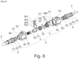
- THE figures 7 And 8 illustrate an electrical connection module 5 according to the invention, intended to form a part of a terminal block of a connection assembly, which integrates two female contact subassemblies 3 according to the invention.
- This module 5 makes it possible to make an electrical connection between a termination 4 of an electrical cable 2 at the input and another at the output.
- This electrical connection module 5 comprises two bodies 50, preferably identical, fixed to each other.
- the fixing means between the two bodies 50 are not shown but they may be screws/nuts passing right through the bodies.
- Each body 50 is electrically insulating with a longitudinal axis X, and intended to house, clamp, lock and connect at least one termination 4 of an electric cable 2.
- each body 50 comprises a cavity 51 within it and the two cavities 51, preferably of the same size, are opposite each other in each of which a termination 4 of electric cable 2 is inserted, tightened and locked, as explained below.
- An electrical cable termination 4 with a central axis X1, comprises an electrically insulating sleeve 41 and a cylindrically shaped electrical contact 40 crimped onto an electrical cable 2, inserted and fixed in particular by snap-fastening, inside the sleeve 41.
- the sleeve 41 comprises on its outer periphery straight grooves 42 which extend around the central axis X1 over part of the length of the sleeve.
- the cylindrical contact 40 is identical to that described with reference to the Figure 5 .
- the interface part 37 with a tool H is mounted freely rotatable in a housing 53 of the body and adapted to be rotated by the tool.
- the interface part 37 may comprise an interface imprint 39 with the tool, preferably a hollow hexagonal imprint. An operator can thus use a standard tool, such as a hexagonal wrench.
- the bridge 353 of the fork 35 bears against the pivot cam 38 and the free end 352 of the branches 350 of the fork bears against a stop 54 internal to the body 50.
- each subassembly 3 has an independent actuating mechanism 37, 38.
- the body 50 comprises a tubular extension 55 with an opening 56 facing the cavity 51,
- Step a1/ As illustrated in Figure 9A , before or during the insertion of the male contact 40 with its sleeve 41 into the opening 56, the interface part 37 and therefore the displacement cam 38 are rotated according to the arrow R1, which causes the fork 35 to pivot around its pivot point 351 on the ring 31 and to bear against the stop 54 of the body 50 and, thereby, the ring 31 to move back according to the arrow A1 and the spring 32 to be compressed.
- the spring 32 is therefore in its compressed state between the plate 52 and the ring 31.
- the rotation of the cam 38 makes it possible to multiply the force exerted by the operator on the interface part 37, and therefore to easily compress the spring 32.
- the petals 301 of the female contact 30 are in a rest position, i.e. not deflected.
- Step b1/ The male contact 40 with its sleeve 41 is inserted into the opening 56.
- the male contact 40 is inserted freely and without mechanical effort between the petals 301 of the female contact 30.
- the spring 32 is still in its compressed state between the plate 52 and the ring 31.
- the ring 31 is still in its rearwardly moved position.
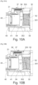
- the petals 301 of the female contact 30 are still in the rest state, i.e. not deflected ( Figures 10A , 11A ).
- the sleeve 41 fits, also without mechanical effort, around the ring 31.
- Step c1/ As illustrated in Figure 9B , 10B , 11B , the male contact 40 is inserted into the female contact 30.
- the interface part 37 and therefore the displacement cam 38 are rotated according to the arrow R2, in the opposite direction to R1, which causes the fork 35 to pivot while pressing against the stop 54 of the body 50 and, thereby, the ring 31 to advance according to the arrow A2, in the opposite direction to A1 and the spring 32 to relax.
- the spring 32 is therefore in its relaxed state between the plate 52 and the ring 31.
- the flexible arms 301 of the female contact 30 are in a deflected position.
- the spring 32 exerts a force to hold the ring in this position.
- the male 40 and female 30 contacts are therefore coupled and locked together.
- FIG. 12 shows advantageous construction variants of the module 5 which has just been described, and which make it possible to obtain a more compact and more robust module, with in addition very good electrical continuity.
- the stop plate 52 of the springs 32 is sandwiched between the two bodies 50 of the module.
- the two female contacts 40 are here screwed into each other. And one of the female contacts 40 (the one on the right on the Figure 12 ) is screwed directly into the stop plate 52.
- the tubular part 300 of one of the contacts 30 is internally tapped with a thread 306 adapted to cooperate with a threaded tail 307 of the other of the contacts.
- the internally tapped tubular part 300 is also externally threaded with a thread 308 which is screwed directly into the plate 52.
- a pre-locking function of a male contact 40 in a body 50 of a module 5 can be provided, which is carried out once the contact 40 is inserted but before the cam 38 is rotated with the ring 31 which deflects the petals 301. of the female contact 30.
- this pre-locking function can be carried out by an operator with one hand. This pre-locking ensures correct axial positioning of the male contact in the female contact, prior to tightening and coupling of the two contacts.
- a first variant of a pre-locking device is shown in Figure 14 .
- a substantially U-shaped part 59, the ends of the branches 590 of which form ribs, is slidably mounted on the tubular extension 55 of the body 50 of the module.
- the tubular extension 55 is provided with two through openings 550 in each of which a rib 590 can be inserted.
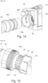
- a second variant of a pre-locking device is shown in Figure 15 .
- At least one protrusion 57 preferably a plurality, is provided at the outer periphery of the tubular extension 55 of the body 50 of the module 5.
- a ring 43 mounted in rotation around the sleeve 41 of the termination 4 comprises at least one lug 430 provided at its inner periphery.
- a part of the module body 50 and an electrical cable termination 4 can be produced so as to block the latter from rotating once its contact is inserted into a cavity 51.
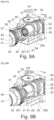
- the opening 56 of the body opposite the cavity 51 is thus provided internally with a plurality of longitudinal straight grooves 560, preferably distributed regularly angularly, each adapted to receive a straight groove 42 formed around the sleeve 40 of the electrical cable termination.
- the grooves 42 allow the torsional forces of the cable 2 to be taken up on the body of the module 3 and also prevent the rotation of the contact 40 by sliding, once inserted and tightened in the connection module 5.
- the grooves 42 are preferably angularly spaced from each other at a small distance, which allows the contact 40 to be inserted into the body 50 of the module, without having to index it in rotation beforehand.
- the pre-locking ring 43 can be put in place once the rotation of the contact 40 is blocked by the grooves 42 ( Figure 16C ).
- a waterproof connection variant between the termination contact(s) 40 and the module body(ies) 50 can be considered.
- this variant may for example consist of installing at least one annular cable gland mounted in the end of the sleeve 41 at the interface with the cable 2.
- an O-ring 381 can be provided arranged around the interface part 38, in its housing 380 ( Figure 12 ).
- connection modules according to the invention allow different connection configurations between electrical harnesses with electrical cable termination 4.
- a single module 5 may comprise two bodies 50, preferably identical, facing and fixed to each other. This allows an electrical connection with a single input and output.
- FIG. 17 illustrates a variant with one electrical input E and three electrical outputs S with an electrical shunt made inside the bodies 50 of a connection module 5'.
- the module 5' comprises two bodies 50 aligned and fixed together, each of the bodies 50 internally comprising two cavities 51 extending parallel to the longitudinal axis (X) of the module.
- the two bodies can be positioned side by side and secured together.
- Each contact 30 is clamped by means of a displacement mechanism 37, 38 independent of the others.
- the electrical shunt is produced by a single plate 52', in electrical connection with the four female contacts 30.
- connection modules is a connection of several terminations 4 of electrical cable 2 to a busbar or connection bar.
- each body 50 of the modules comprises a single cavity 51 in which a contact 40 of a termination 4 of an electric cable 2 is inserted and clamped.
- a stop plate 52 includes an extension portion 520 that extends outwardly from the body 30.
- Each body 50 comprises an extension 500 of straight parallelepiped shape, which supports an extension portion 520 of the stop plate 52.
- the female contact 30 comprises a tail 307 screwed into the stop plate 52.
- the parallel electrical connection between the different female contacts 30 and therefore between the electrical terminations 4 is made by a common busbar 6 which is fixed by means of a screw/nut 60 in the extension portion 520 of each stop plate 52. It is of course possible to envisage, instead of the screws/nuts 60, fixing by welding to the busbar.
- Modules of different dimensions can be provided with a different number of cavities to accommodate 4 different sized electrical cable terminations.
- connection module in a support rail.
- the longitudinal straight grooves are made in the body and the complementary straight grooves are carried by the sleeve, one can obviously envisage the reverse, that is to say with the grooves made in the body and the sleeve being provided on its periphery with longitudinal straight grooves.
Landscapes
- Engineering & Computer Science (AREA)
- Architecture (AREA)
- Civil Engineering (AREA)
- Structural Engineering (AREA)
- Details Of Connecting Devices For Male And Female Coupling (AREA)
Applications Claiming Priority (1)
| Application Number | Priority Date | Filing Date | Title |
|---|---|---|---|
| FR2312555A FR3155651A1 (fr) | 2023-11-16 | 2023-11-16 | Sous-ensemble de contact de puissance à accouplement sans effort, Module de connexion de puissance intégrant un tel sous-ensemble pour le serrage d’une terminaison de câble électrique. |
Publications (3)
| Publication Number | Publication Date |
|---|---|
| EP4557528A1 true EP4557528A1 (de) | 2025-05-21 |
| EP4557528B1 EP4557528B1 (de) | 2025-12-17 |
| EP4557528C0 EP4557528C0 (de) | 2025-12-17 |
Family
ID=90243671
Family Applications (1)
| Application Number | Title | Priority Date | Filing Date |
|---|---|---|---|
| EP24212925.2A Active EP4557528B1 (de) | 2023-11-16 | 2024-11-14 | Kraftlose kupplungsleistungskontaktbaugruppe, leistungsanschlussmodul mit einer solchen baugruppe zum klemmen eines stromkabelabschlusses |
Country Status (5)
| Country | Link |
|---|---|
| US (1) | US20250070488A1 (de) |
| EP (1) | EP4557528B1 (de) |
| CN (1) | CN120016182A (de) |
| ES (1) | ES3064086T3 (de) |
| FR (1) | FR3155651A1 (de) |
Families Citing this family (1)
| Publication number | Priority date | Publication date | Assignee | Title |
|---|---|---|---|---|
| CN120497705B (zh) * | 2025-05-22 | 2025-12-12 | 国网湖北省电力有限公司荆州供电公司 | 一种枪击型带电分流装备 |
Citations (5)
| Publication number | Priority date | Publication date | Assignee | Title |
|---|---|---|---|---|
| GB114429A (en) * | 1917-03-12 | 1918-05-16 | Henri De La Valette | Improvements in Electric Couplings. |
| US7563134B2 (en) * | 2007-07-06 | 2009-07-21 | Hyundai Motor Company | Coaxial cable connector |
| CN211404771U (zh) * | 2020-02-25 | 2020-09-01 | 广东纳特康电子股份有限公司 | 限位压线式端子台连接器 |
| EP3758165A1 (de) | 2019-06-26 | 2020-12-30 | Radiall | Anschlussmodul, anschlusseinheit mit klemmleiste mit einer vielzahl von solchen anschlussmodulen und luftfahrzeugstruktur mit solcher anschlusseinheit |
| US10903596B2 (en) * | 2018-10-25 | 2021-01-26 | Razvan Ilie | Electrical connector having a plurality of restraints |
-
2023
- 2023-11-16 FR FR2312555A patent/FR3155651A1/fr active Pending
-
2024
- 2024-11-12 US US18/945,075 patent/US20250070488A1/en active Pending
- 2024-11-14 EP EP24212925.2A patent/EP4557528B1/de active Active
- 2024-11-14 ES ES24212925T patent/ES3064086T3/es active Active
- 2024-11-15 CN CN202411634433.2A patent/CN120016182A/zh active Pending
Patent Citations (5)
| Publication number | Priority date | Publication date | Assignee | Title |
|---|---|---|---|---|
| GB114429A (en) * | 1917-03-12 | 1918-05-16 | Henri De La Valette | Improvements in Electric Couplings. |
| US7563134B2 (en) * | 2007-07-06 | 2009-07-21 | Hyundai Motor Company | Coaxial cable connector |
| US10903596B2 (en) * | 2018-10-25 | 2021-01-26 | Razvan Ilie | Electrical connector having a plurality of restraints |
| EP3758165A1 (de) | 2019-06-26 | 2020-12-30 | Radiall | Anschlussmodul, anschlusseinheit mit klemmleiste mit einer vielzahl von solchen anschlussmodulen und luftfahrzeugstruktur mit solcher anschlusseinheit |
| CN211404771U (zh) * | 2020-02-25 | 2020-09-01 | 广东纳特康电子股份有限公司 | 限位压线式端子台连接器 |
Also Published As
| Publication number | Publication date |
|---|---|
| US20250070488A1 (en) | 2025-02-27 |
| FR3155651A1 (fr) | 2025-05-23 |
| EP4557528B1 (de) | 2025-12-17 |
| ES3064086T3 (en) | 2026-04-22 |
| CN120016182A (zh) | 2025-05-16 |
| EP4557528C0 (de) | 2025-12-17 |
Similar Documents
| Publication | Publication Date | Title |
|---|---|---|
| EP3758161B1 (de) | Elektrische verbindungsbaugruppe, klemmleiste und flugzeugstruktur | |
| EP3758154B1 (de) | Stromanschlussmodul mit verriegelungs-/entriegelungssystem der stromkabelenden in dem modul, klemmleiste, die eine vielzahl von unabhängigen anschlussmodulen umfasst | |
| EP2255417B1 (de) | Verfahren zur beschleunigung der individuellen elektromagnetischen abschirmung eines elektrischen kabelstrangs in einem elektrischen verbinder | |
| EP4557528B1 (de) | Kraftlose kupplungsleistungskontaktbaugruppe, leistungsanschlussmodul mit einer solchen baugruppe zum klemmen eines stromkabelabschlusses | |
| EP3758165B1 (de) | Anschlussmodul, anschlusseinheit mit klemmleiste mit einer vielzahl von solchen anschlussmodulen und luftfahrzeugstruktur mit solcher anschlusseinheit | |
| EP3323170B1 (de) | Frei verschiebbare elektrische verbindungsvorrichtung mit schutz gegen schäden durch fremdkörper | |
| FR2819943A1 (fr) | Connecteur electrique a contacts multiples | |
| EP0681351B1 (de) | Omnidirektionale elektrische Stecker mit mehr Phasen | |
| EP0595708B1 (de) | Vorrichtung zum Verhindern des Schwindens der Isolation für kunststoffisolierte Energiekabel | |
| EP4557526B1 (de) | Leistungsanschlussmodul zum klemmen eines elektrischen kabelabschlusses durch ein blatt, dessen mindestens ein verformbares teil zur bildung eines anschlussblockteils einer verbindungsanordnung bildet | |
| FR2718299A1 (fr) | Prise de masse sur blindage de câble électrique. | |
| EP0050560B1 (de) | Seismisches Kabelverbindungsstück mit flachen Verbindungen | |
| FR2758661A1 (fr) | Dispositif de raccordement mecanique et de connexion electrique | |
| FR3017494A1 (fr) | Connecteur tetrapolaire a serrage commun pour cable a neutre distribue | |
| FR2662846A1 (fr) | Connecteur pour la jonction de conducteurs electriques, notamment en reseau souterrain. | |
| FR2794902A1 (fr) | Connecteur de derivation compact d'au moins un cable de derivation de neutre sur un cable principal de neutre et mise a la terre simultanee | |
| FR3125174A1 (fr) | Dispositif de connexion électrique comportant des embouts mis bout à bout | |
| EP0821835A1 (de) | Hinterverbindungsvorrichtung für elektrischen stecker für abgeschirmtes kabel | |
| FR2998723A1 (fr) | Systeme d'ancrage pour cable electrique isole, comportant une pince d'ancrage et un connecteur pour relier electriquement le cable electrique isole a la pince d'ancrage | |
| EP3633690A1 (de) | Mehradriges stromkabel | |
| FR3086808A1 (fr) | Connecteur | |
| FR3034574A3 (fr) | Connecteur bnc pour cables coaxiaux | |
| FR2473798A1 (fr) | Connecteur deformable pour raccordement de conducteurs electriques nus | |
| EP3062407B1 (de) | Anschlussmuffe zwischen leiterkabeln, herstellungsverfahren und einbauverfahren einer solchen muffe | |
| FR2683957A1 (fr) | Pince a denudage thermique. |
Legal Events
| Date | Code | Title | Description |
|---|---|---|---|
| PUAI | Public reference made under article 153(3) epc to a published international application that has entered the european phase |
Free format text: ORIGINAL CODE: 0009012 |
|
| STAA | Information on the status of an ep patent application or granted ep patent |
Free format text: STATUS: REQUEST FOR EXAMINATION WAS MADE |
|
| 17P | Request for examination filed |
Effective date: 20241114 |
|
| AK | Designated contracting states |
Kind code of ref document: A1 Designated state(s): AL AT BE BG CH CY CZ DE DK EE ES FI FR GB GR HR HU IE IS IT LI LT LU LV MC ME MK MT NL NO PL PT RO RS SE SI SK SM TR |
|
| GRAP | Despatch of communication of intention to grant a patent |
Free format text: ORIGINAL CODE: EPIDOSNIGR1 |
|
| STAA | Information on the status of an ep patent application or granted ep patent |
Free format text: STATUS: GRANT OF PATENT IS INTENDED |
|
| RIC1 | Information provided on ipc code assigned before grant |
Ipc: H01R 13/11 20060101AFI20250923BHEP Ipc: H01R 13/193 20060101ALI20250923BHEP |
|
| INTG | Intention to grant announced |
Effective date: 20251002 |
|
| GRAS | Grant fee paid |
Free format text: ORIGINAL CODE: EPIDOSNIGR3 |
|
| GRAA | (expected) grant |
Free format text: ORIGINAL CODE: 0009210 |
|
| STAA | Information on the status of an ep patent application or granted ep patent |
Free format text: STATUS: THE PATENT HAS BEEN GRANTED |
|
| AK | Designated contracting states |
Kind code of ref document: B1 Designated state(s): AL AT BE BG CH CY CZ DE DK EE ES FI FR GB GR HR HU IE IS IT LI LT LU LV MC ME MK MT NL NO PL PT RO RS SE SI SK SM TR |
|
| REG | Reference to a national code |
Ref country code: CH Ref legal event code: F10 Free format text: ST27 STATUS EVENT CODE: U-0-0-F10-F00 (AS PROVIDED BY THE NATIONAL OFFICE) Effective date: 20251217 Ref country code: GB Ref legal event code: FG4D Free format text: NOT ENGLISH |
|
| REG | Reference to a national code |
Ref country code: DE Ref legal event code: R096 Ref document number: 602024001743 Country of ref document: DE |
|
| U01 | Request for unitary effect filed |
Effective date: 20260108 |
|
| U07 | Unitary effect registered |
Designated state(s): AT BE BG DE DK EE FI FR IT LT LU LV MT NL PT RO SE SI Effective date: 20260114 |
|
| PG25 | Lapsed in a contracting state [announced via postgrant information from national office to epo] |
Ref country code: NO Free format text: LAPSE BECAUSE OF FAILURE TO SUBMIT A TRANSLATION OF THE DESCRIPTION OR TO PAY THE FEE WITHIN THE PRESCRIBED TIME-LIMIT Effective date: 20260317 |
|
| PG25 | Lapsed in a contracting state [announced via postgrant information from national office to epo] |
Ref country code: HR Free format text: LAPSE BECAUSE OF FAILURE TO SUBMIT A TRANSLATION OF THE DESCRIPTION OR TO PAY THE FEE WITHIN THE PRESCRIBED TIME-LIMIT Effective date: 20251217 |
|
| PG25 | Lapsed in a contracting state [announced via postgrant information from national office to epo] |
Ref country code: RS Free format text: LAPSE BECAUSE OF FAILURE TO SUBMIT A TRANSLATION OF THE DESCRIPTION OR TO PAY THE FEE WITHIN THE PRESCRIBED TIME-LIMIT Effective date: 20260317 |
|
| REG | Reference to a national code |
Ref country code: ES Ref legal event code: FG2A Ref document number: 3064086 Country of ref document: ES Kind code of ref document: T3 Effective date: 20260422 |