EP4559408A2 - Cadre de maintien d'écarteur chirurgical - Google Patents
Cadre de maintien d'écarteur chirurgical Download PDFInfo
- Publication number
- EP4559408A2 EP4559408A2 EP24211542.6A EP24211542A EP4559408A2 EP 4559408 A2 EP4559408 A2 EP 4559408A2 EP 24211542 A EP24211542 A EP 24211542A EP 4559408 A2 EP4559408 A2 EP 4559408A2
- Authority
- EP
- European Patent Office
- Prior art keywords
- retractor
- bore
- support body
- support frame
- frame arm
- Prior art date
- Legal status (The legal status is an assumption and is not a legal conclusion. Google has not performed a legal analysis and makes no representation as to the accuracy of the status listed.)
- Pending
Links
Images



Classifications
-
- A—HUMAN NECESSITIES
- A61—MEDICAL OR VETERINARY SCIENCE; HYGIENE
- A61B—DIAGNOSIS; SURGERY; IDENTIFICATION
- A61B17/00—Surgical instruments, devices or methods
- A61B17/02—Surgical instruments, devices or methods for holding wounds open, e.g. retractors; Tractors
- A61B17/0218—Surgical instruments, devices or methods for holding wounds open, e.g. retractors; Tractors for minimally invasive surgery
-
- A—HUMAN NECESSITIES
- A61—MEDICAL OR VETERINARY SCIENCE; HYGIENE
- A61B—DIAGNOSIS; SURGERY; IDENTIFICATION
- A61B17/00—Surgical instruments, devices or methods
- A61B17/02—Surgical instruments, devices or methods for holding wounds open, e.g. retractors; Tractors
- A61B17/0206—Surgical instruments, devices or methods for holding wounds open, e.g. retractors; Tractors with antagonistic arms as supports for retractor elements
-
- A—HUMAN NECESSITIES
- A61—MEDICAL OR VETERINARY SCIENCE; HYGIENE
- A61B—DIAGNOSIS; SURGERY; IDENTIFICATION
- A61B90/00—Instruments, implements or accessories specially adapted for surgery or diagnosis and not covered by any of the groups A61B1/00 - A61B50/00, e.g. for luxation treatment or for protecting wound edges
- A61B90/50—Supports for surgical instruments, e.g. articulated arms
- A61B90/57—Accessory clamps
-
- A—HUMAN NECESSITIES
- A61—MEDICAL OR VETERINARY SCIENCE; HYGIENE
- A61B—DIAGNOSIS; SURGERY; IDENTIFICATION
- A61B17/00—Surgical instruments, devices or methods
- A61B2017/00477—Coupling
-
- A—HUMAN NECESSITIES
- A61—MEDICAL OR VETERINARY SCIENCE; HYGIENE
- A61B—DIAGNOSIS; SURGERY; IDENTIFICATION
- A61B17/00—Surgical instruments, devices or methods
- A61B2017/00526—Methods of manufacturing
-
- A—HUMAN NECESSITIES
- A61—MEDICAL OR VETERINARY SCIENCE; HYGIENE
- A61B—DIAGNOSIS; SURGERY; IDENTIFICATION
- A61B90/00—Instruments, implements or accessories specially adapted for surgery or diagnosis and not covered by any of the groups A61B1/00 - A61B50/00, e.g. for luxation treatment or for protecting wound edges
- A61B90/50—Supports for surgical instruments, e.g. articulated arms
Definitions
- the present invention relates generally to surgical retractors and more particularly, to a retractor frame holding assembly and related methods involving the same.
- Open and mini-open surgical procedures require multiple instruments, e.g., for retracting and holding both instruments and the patient's tissue.
- soft tissue surgical procedures such as about the shoulder or hip, that require such an open or mini-open technique, as opposed to an arthroscopic technique.
- These open or mini-open procedures require expensive resources, including but not limited to additional staff surgeons and assistants to hold the various retraction and/or surgical instruments.
- a retractor holding frame includes a support body including a first bore extending transversely from a first side of the support body to a second side of the support body opposite the first side, and a second bore extending transversely from the second side to the first side.
- the frame includes a left support frame arm including a first annular hub configured to be disposed within the first bore and a first plurality of posts disposed along an outer edge of the left support frame arm configured to retain a first retractor in a first orientation.
- the frame includes a right support frame arm including a second annular hub configured to be disposed within the second bore and a second plurality of posts disposed along an outer edge of the right support frame arm configured to retain a second retractor in a second orientation.
- a method of using a retractor holding frame includes inserting a first annular hub of a left support frame arm into a first bore of a support body.
- the first bore extends transversely through the support body from a first side of the support body to a second side of the support body opposite the first side.
- the method includes fixing the left support frame arm in a desired orientation with respect to the support body by disposing a first retaining pin of a first spring-biased locking mechanism of the support body down into the first bore such that the first retaining pin is received into one of a first annular series of detents disposed in the first annular hub of the left support frame arm.
- the method includes inserting a second annular hub of a right support frame arm into a second bore of the support body.
- the second bore extends transversely through the support body from the second side to the first side.
- the method includes fixing the right support frame arm in a desired orientation with respect to the support body by disposing a second retaining pin of a second spring-biased locking mechanism of the support body down into the second bore such that the second retaining pin is received into one of a second annular series of detents disposed in the second annular hub of the right support frame arm.
- a method of manufacturing a retractor holding frame includes providing a support body having a first side and a second side opposite the first side. The method includes forming a first bore extending transversely through the support body from the first side to the second side. The method includes forming a second bore extending transversely through the support body from the second side to the first. The method includes providing a left support frame arm including a first annular hub configured to be disposed within the first bore of the support body, and a first plurality of posts disposed along an outer edge of the left support frame arm and configured to receive and retain at least a first retractor in a first desired orientation.
- the method includes providing a right support frame arm including a second annular hub configured to be disposed within the second bore of the support body, and a second plurality of posts disposed along an outer edge of the right support frame arm and configured to receive and retain at least a second retractor in a second desired orientation.
- Implementations of the technology described herein are directed generally to a retractor holding frame assembly and related methods.
- a specific method of measuring the characteristic or property may be defined herein as well.
- the measurement method should be interpreted as the method of measurement that would most likely be adopted by one of ordinary skill in the art given the description and context of the characteristic or property.
- the value or range of values should be interpreted as being met regardless of which method of measurement is chosen.
- any methods disclosed herein comprise one or more steps or actions for achieving the described method.
- the method steps and/or actions may be interchanged with one another without departing from the scope of the claims.
- the order and/or use of specific steps and/or actions may be modified without departing from the scope of the claims.
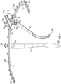
- FIG. 1 provides a left-side perspective view of retractor holding frame 10
- FIGs. 3 and 4 provide center and right-side perspective views of retractor holding frame 10, respectively.
- Retractor holding frame 10 can include a left support frame arm 11 and a right support frame arm 12. Left and right support frame arms 11, 12 are each independently and adjustably supported by support body 13. Support body 13 is, in turn, adjustably supported from a surgical table by an adjustable support arm (not shown).
- support body 13 includes a first bore 14 extending transversely through support body 13 from a first side of support body 13 to a second side of support body 13 opposite the first side.
- Support body 13 also includes a second bore 15 extending transversely through support body 13 from the second side of support body 13 to the first side of support body 13.
- First bore 14 is configured to receive at least a portion of left support frame arm 11 at the first side of support body 13 and second bore 15 is configured to receive at least a portion of right support frame arm 12 at the second side of support body 13.
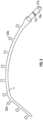
- left support frame arm 11 is provided with an annular hub 16a configured to be disposed in first bore 14 in support body 13.
- right support frame arm 12 in FIG. 6 right support frame arm 12 is provided with an annular hub 16b configured to be disposed in second bore 15 in support body 13.
- each of first and second bores 14, 15 and each of the respective first and second annular hubs 16a, 16b of left and right support frame arms 11, 12 have substantially circular cross-sections so as to allow respective annular hubs 16a, 16b of left and right support frame arms 11, 12 to fit and rotate within respective first and second bores 14, 15 of support body 13.
- each of first and second annular hubs 16a, 16b have respective tapered distal ends 27a, 27b, which allow for easy alignment and insertion of respective first and second annular hubs 16a, 16b into respective first and second bores 14, 15.
- each of first and second annular hubs 16a, 16b further include a respective annular series of recesses or detents 17a', 17b' configured to selectively receive a respective retaining pin 17a, 17b of a respective spring-biased locking mechanism 18a, 18b disposed on a top surface of support body 13.
- respective retaining pins 17a, 17b are configured to extend down into respective first and second bores 14, 15, under force provided by respective spring-biased locking mechanisms 18a, 18b, and seat and/or index within a respective one of the respective annular series of recesses or detents 17a', 17b' of respective hubs 16a, 16b.
- respective portions of spring-biased locking mechanisms 18a, 18b can be pulled upwardly to thereby retract respective retaining pins 17a, 17b sufficiently to allow respective annular hubs 16a, 16b of respective left and right support frame arms 11, 12 to be inserted into respective first and second bores 14, 15 and respective left and right support frame arms 11, 12 to be rotated to respective desired positions.
- Support body 13 is further provided with a quick-connect connector 28 for coupling support body 13 to a positioning arm (not shown) which, in turn, adjustably supports retractor holding frame 10 from a surgical table.
- a positioning arm (not shown) which, in turn, adjustably supports retractor holding frame 10 from a surgical table.
- a number of conventional positioning arms are available on the market.
- left and right support frame arms 11, 12 having any suitable shape.
- left and right support frame arms 11, 12 may have a substantially curved shape as illustrated in FIGs. 1 and 3-6 .
- one or both of left and right support frame arms 11, 12 could also and/or alternatively have a substantially straight shape, or one or more portions may have a substantially curved shape, while one or more other portions may have a substantially curved shape to suit the particular application.
- different sized and/or shaped left and right support frame arms 11, 12 may be readily substituted, inserted and/or removed from support body 13 as described above.
- Left and right support frame arms 11, 12 each further include a respective plurality of retaining hooks or posts 20a, 20b disposed along their outside edges and configured to receive and retain one or more retractors 21 in position.
- one or more retractors 21 may each be provided with a series of apertures 22a at a proximal end 23a and such apertures 22a are configured to receive one of hooks or posts 20a, 20b and thereby retain proximal ends 23a of retractors 21 on those respective hooks or posts 20a, 20b.
- Retractors 21 may have any suitable shape.
- retractors 21 may have at least one curved portion. For example, as illustrated in FIGs.
- proximal 23a and distal 26a ends of retractor 21 can be substantially curved.
- retractors 21 may have at least one substantially straight portion.
- a medial portion of retractor 21 can be substantially straight.
- at least a portion of retractor 21 can be tapered.
- retractor 21 can taper along its length of extension at least from its medial portion to distal end 26a. Such a tapered aspect may allow retractors 21 to more effectively focus retention force to a particular portion of a patient's tissue. It should also be appreciated that, while the figures illustrate one retractor 21 disposed on left support frame arm 11, one or more retractors 21 can also or alternatively be similarly disposed on right support frame 12.
- an underside of support body 13 can further include one or more hooks or posts 24 configured to receive and retain in position one or more additional retractors 25.
- one or more additional retractors 25 can each be provided with a similar series of apertures 22b at a similar proximal end 23b of additional retractors 25, and such apertures 22b of additional retractors 25 are configured to receive one of hooks or posts 24 on underside of support body 13 and thereby retain proximal end(s) 23b of additional retractor(s) 25 on respective hooks or posts 24.
- retractors 25 may have any suitable shape.
- retractors 25 may have at least one curved portion. For example, as illustrated in FIGs.
- proximal 23b and distal 26b ends of retractor 25 can be substantially curved.
- retractors 25 may have at least one substantially straight portion.
- a medial portion of retractor 25 can be substantially straight.
- at least a portion of retractor 25 can be tapered.
- retractor 25 can taper along its length of extension at least from its medial portion to distal end 26b. Such a tapered aspect may allow retractors 25 to more effectively focus retention force to a particular portion of a patient's tissue.
- respective distal ends 26a, 26b of retractors 21, 25 may be adjustably positioned to retain and spread patient tissue at an incision made at a surgical access point on the patient. This allows the surgeon to securely place and hold a set of retractors 21, 25 during a surgical procedure without the need for additional surgical staff.
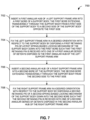
- FIG. 7 illustrates a flowchart 700 corresponding to such a method of use, in accordance with some embodiments. While flowchart 700 illustrates one or more actions and/or steps, it should be understood that one or more described actions can be omitted, one or more additional or alternative actions can be added, and/or one or more actions can be performed in another order than that specifically described without departing from the spirit or scope of the present disclosure.
- Block 702 includes inserting a first annular hub of a left support frame arm into a first bore of a support body, the first bore extending transversely through the support body from a first side of the support body to a second side of the support body opposite the first side.
- first annular hub 16a of left support frame arm 11 can be inserted into first bore 14 of support body 13.
- First bore 14 extends transversely through support body 13 from a first side of support body 13 to a second side of support body 13 opposite the first side.
- inserting the first annular hub of the left support frame arm into the first bore of the support body includes utilizing at least a portion of first spring-biased locking mechanism 18a to retract first retaining pin 17a sufficiently from first bore 14 to allow annular hub 16a of left support frame arm 11 to be inserted into first bore 14.
- first annular hub 16a has a tapered distal end 27a configured to aid alignment between first annular hub 16a and first bore 14.
- Block 704 includes fixing the left support frame arm in a desired orientation with respect to the support body by disposing a first retaining pin of a first spring-biased locking mechanism of the support body down into the first bore such that the first retaining pin is received into one of a first annular series of detents disposed in the first annular hub of the left support frame arm.
- left support frame arm 11 can be fixed in a desired orientation with respect to support body 13 by disposing first retaining pin 17a of first spring-biased locking mechanism 18a of support body 13 down into first bore 14 such that first retaining pin 17a is received into one of a first annular series of detents 17a' disposed in annular hub 16a of left support frame arm 11.
- fixing the left support frame arm in the desired orientation with respect to the support body includes first rotating left support frame arm 11 to the desired orientation while its annular hub 16a is disposed within first bore 14 and first retaining pin 17a is retracted from first bore 14.
- left support frame arm 11 further comprises first plurality of posts 20a disposed along an outer edge of left support frame arm 11.
- flowchart 700 may further include securing one of a series of apertures 22a, disposed at a proximal end 23a of a first retractor 21, to one of the first plurality of posts 20a of left support frame arm 11 to thereby retain first retractor 21 in a first desired orientation.
- Block 706 includes inserting a second annular hub of a right support frame arm into a second bore of the support body, the second bore extending transversely through the support body from the second side to the first side.
- annular hub 16b of right support frame arm 12 can be inserted into second bore 15 of support body 13.
- Second bore 15 extends transversely through support body 13 from the second side of support body 13 to the first side of support body 13.
- inserting the second annular hub of the right support frame arm into the second bore of the support body includes utilizing at least a portion of second spring-biased locking mechanism 18b to retract second retaining pin 17b sufficiently from second bore 15 to allow annular hub 16b of right support frame arm 12 to be inserted into second bore 15.
- second annular hub 16b has a tapered distal end 27b configured to aid alignment between second annular hub 16b and second bore 15.
- Block 708 includes fixing the right support frame arm in a desired orientation with respect to the support body by disposing a second retaining pin of a second spring-biased locking mechanism of the support body down into the second bore such that the second retaining pin is received into one of a second annular series of detents disposed in the second annular hub of the right support frame arm.
- right support frame arm 12 can be fixed in a desired orientation with respect to support body 13 by disposing second retaining pin 17a of second spring-biased locking mechanism 18b of support body 13 down into second bore 15 such that second retaining pin 17b is received into one of a second annular series of detents 17b' disposed in annular hub 16b of right support frame arm 12.
- fixing the right support frame arm in the desired orientation with respect to the support body includes first rotating right support frame arm 12 to the desired orientation while its annular hub 16b is disposed within second bore 15 and second retaining pin 17b is retracted from second bore 15.
- an underside of support body 13 further comprises at least one post 24 and flowchart 700 can further include securing one of a series of apertures 22b, disposed at a proximal end 23b of an additional retractor 25, to one of the at least one post 24 on the underside of support body 13 to thereby retain additional retractor 25 in an additional desired orientation.
- each of the first and second annular hubs 16a, 16b, first bore 14 and second bore 15 have a circular cross-section, thereby allowing the first annular hub 16ab to rotate within first bore 14 and left support frame arm 11 to rotate with respect to support body 13 and thereby allowing the second annular hub 16b to rotate within second bore 15 and right support frame arm 12 to rotate with respect to support body 13.
- support body 13 further includes quick-connect connector 28 and flowchart 700 can further include coupling support body 13 to a positioning arm utilizing quick-connect connector 28.
- at least one respective portion of each of left and right support frame arms 11,12 has a curved shape.
- at least one respective portion of each of left and right support frame arms 11, 12 has a substantially straight shape.
- at least one of first and second retractors 21 taper along their respective lengths.
- first and second retractors 21 each comprise at least one curved portion.
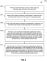
- FIG. 8 illustrates a flowchart 800 corresponding to such a method of manufacture, in accordance with some embodiments. While flowchart 800 illustrates one or more actions and/or steps, it should be understood that one or more described actions can be omitted, one or more additional or alternative actions can be added, and/or one or more actions can be performed in another order than that specifically described without departing from the spirit or scope of the present disclosure.
- Block 802 includes providing a support body having a first side and a second side opposite the first side.
- a support body having a first side and a second side opposite the first side.
- Block 804 includes forming a first bore extending transversely through the support body from the first side to the second side.
- first bore 14 can be formed to extend transversely through support body 13 from a first side of support body 13 to a second side of support body 13 opposite the first side.
- Block 806 includes forming a second bore extending transversely through the support body from the second side to the first side.
- second bore 15 extends transversely through support body 13 from the second side of support body 13 to the first of support body 13.
- Block 808 includes providing a left support frame arm comprising a first annular hub configured to be disposed within the first bore of the support body, and a first plurality of posts disposed along an outer edge of the left support frame arm and configured to receive and retain at least a first retractor in a first desired orientation.
- left support frame arm 11 can be provided including annular hub 16a configured to be disposed within first bore 14 of support body 13, and a first plurality of posts 20a disposed along an outer edge of left support frame arm 11 and configured to receive and retain at least a first retractor 21 in a first desired orientation.
- Block 810 includes providing a right support frame arm comprising a second annular hub configured to be disposed within the second bore of the support body, and a second plurality of posts disposed along an outer edge of the right support frame arm and configured to receive and retain at least a second retractor in a second desired orientation.
- right support frame arm 12 can be provided including annular hub 16b configured to be disposed within second bore 15 of support body 13, and a second plurality of posts 20b disposed along an outer edge of right support frame arm 12 and configured to receive and retain at least a second retractor 21 in a second desired orientation.
- each of first and second annular hubs 16a, 16b, first bore 14 and second bore 15 are formed to have a circular cross-section, thereby allowing the first annular hub 16a to rotate within first bore 14 and left support frame arm 11 to rotate with respect to support body 13 and thereby allowing the second annular hub 16b to rotate within second bore 15 and right support frame arm 12 to rotate with respect to support body 13.
- flowchart 800 can further include disposing at least one post 24 on an underside of support body 13 such that the at least one post 24 is configured to receive and retain at least one additional retractor 25 in an additional desired orientation.
- flowchart 800 can further include forming a tapered distal end 27a on first annular hub 16a to aid alignment between first annular hub 16a and first bore 14. In some embodiments, flowchart 800 can further include forming a tapered distal end 27b on the second annular hub 16b to aid alignment between second annular hub 16b and second bore 15.
- flowchart 800 can further include providing a first spring-biased locking mechanism 18a, including a first retaining pin 17a configured to extend down into first bore 14, on support body 13.
- providing the first spring-biased locking mechanism includes providing at least a portion of the first spring-biased locking mechanism 18a that is configured to retract the first retaining pin 17a sufficiently from first bore 14 to allow first annular hub 16a to be inserted into first bore 14 or left support frame arm 11 to be rotated with respect to support body 13 while first annular hub 16a is disposed within first bore 14.
- flowchart 800 can further include providing second spring-biased locking mechanism 18b, including second retaining pin 17b configured to extend down into second bore 15, on support body 13.
- providing second spring-biased locking mechanism 18b includes providing at least a portion of second spring-biased locking mechanism 18b that is configured to retract second retaining pin 17b sufficiently from second bore 15 to allow second annular hub 16b to be inserted into second bore 15 or right support frame arm 12 to be rotated with respect to support body 13 while second annular hub 16b is disposed within second bore 15.
- flowchart 800 can further include forming a first annular series of detents 17a' in first annular hub 16a configured to selectively receive first retaining pin 17a and thereby fix left support frame arm 11 in a desired orientation with respect to support body 13.
- flowchart 800 can further include forming a second annular series of detents 17b' in second annular hub 16b configured to selectively receive second retaining pin 17b and thereby fix right support frame arm 12 in a desired orientation with respect to support body 13.
- flowchart 800 can further include securing quick-connect connector 28 to support body 13, quick-connect connector 28 being configured to couple support body 13 to a positioning arm.
- At least one respective portion of each of left and right support frame arms 11, 12 has a curved shape. In some embodiments, at least one respective portion of each of left and right support frame arms 11, 12 has a substantially straight shape.
- flowchart 800 can further include providing the first retractor 21 having a series of apertures 22a disposed at proximal end 23b thereof, the series of apertures 22a configured to receive a post of first plurality of posts 20b of left support frame arm 11 and thereby retain proximal end 23a of first retractor 21 thereon.
- flowchart 800 can further include providing the second retractor 21 having a series of apertures 22a disposed at a proximal end 23a thereof, the series of apertures 22a configured to receive a post of the second plurality of posts 20b of right support frame arm 12 and thereby retain proximal end 23a of second retractor 21 thereon.
- flowchart 800 can further include providing the additional retractor 25 having a series of apertures 22b disposed at a proximal end 23b thereof, the series of apertures 22b configured to receive the at least one post 24 on the underside of support body 13 and thereby retain proximal end 23b of additional retractor 25 thereon.
- At least one of the first and second retractors 21 tapers along their respective lengths. In some embodiments, the first and second retractors 21 each comprise at least one curved portion.
Landscapes
- Health & Medical Sciences (AREA)
- Life Sciences & Earth Sciences (AREA)
- Surgery (AREA)
- Molecular Biology (AREA)
- Engineering & Computer Science (AREA)
- Biomedical Technology (AREA)
- Heart & Thoracic Surgery (AREA)
- Medical Informatics (AREA)
- Nuclear Medicine, Radiotherapy & Molecular Imaging (AREA)
- Animal Behavior & Ethology (AREA)
- General Health & Medical Sciences (AREA)
- Public Health (AREA)
- Veterinary Medicine (AREA)
- Oral & Maxillofacial Surgery (AREA)
- Pathology (AREA)
- Surgical Instruments (AREA)
Applications Claiming Priority (3)
| Application Number | Priority Date | Filing Date | Title |
|---|---|---|---|
| US202062984363P | 2020-03-03 | 2020-03-03 | |
| EP21715010.1A EP4114277B1 (fr) | 2020-03-03 | 2021-03-02 | Cadre de maintien d'écarteur chirurgical |
| PCT/US2021/020400 WO2021178365A1 (fr) | 2020-03-03 | 2021-03-02 | Cadre de maintien d'écarteur chirurgical |
Related Parent Applications (3)
| Application Number | Title | Priority Date | Filing Date |
|---|---|---|---|
| PCT/US2021/020400 Previously-Filed-Application WO2021178365A1 (fr) | 2020-03-03 | 2021-03-02 | Cadre de maintien d'écarteur chirurgical |
| EP21715010.1A Division EP4114277B1 (fr) | 2020-03-03 | 2021-03-02 | Cadre de maintien d'écarteur chirurgical |
| EP21715010.1A Division-Into EP4114277B1 (fr) | 2020-03-03 | 2021-03-02 | Cadre de maintien d'écarteur chirurgical |
Publications (2)
| Publication Number | Publication Date |
|---|---|
| EP4559408A2 true EP4559408A2 (fr) | 2025-05-28 |
| EP4559408A3 EP4559408A3 (fr) | 2025-07-23 |
Family
ID=75267583
Family Applications (2)
| Application Number | Title | Priority Date | Filing Date |
|---|---|---|---|
| EP21715010.1A Active EP4114277B1 (fr) | 2020-03-03 | 2021-03-02 | Cadre de maintien d'écarteur chirurgical |
| EP24211542.6A Pending EP4559408A3 (fr) | 2020-03-03 | 2021-03-02 | Cadre de maintien d'écarteur chirurgical |
Family Applications Before (1)
| Application Number | Title | Priority Date | Filing Date |
|---|---|---|---|
| EP21715010.1A Active EP4114277B1 (fr) | 2020-03-03 | 2021-03-02 | Cadre de maintien d'écarteur chirurgical |
Country Status (7)
| Country | Link |
|---|---|
| US (2) | US11395646B2 (fr) |
| EP (2) | EP4114277B1 (fr) |
| JP (1) | JP7466668B2 (fr) |
| KR (1) | KR102913166B1 (fr) |
| AU (1) | AU2021229480B2 (fr) |
| ES (1) | ES3014369T3 (fr) |
| WO (1) | WO2021178365A1 (fr) |
Families Citing this family (2)
| Publication number | Priority date | Publication date | Assignee | Title |
|---|---|---|---|---|
| EP4114277B1 (fr) * | 2020-03-03 | 2024-12-25 | Encore Medical, L.P. dba DJO Surgical | Cadre de maintien d'écarteur chirurgical |
| US20250248701A1 (en) * | 2022-04-10 | 2025-08-07 | Dessinrx Healthcare Pvt. Ltd | Skin flap retraction device |
Family Cites Families (19)
| Publication number | Priority date | Publication date | Assignee | Title |
|---|---|---|---|---|
| US3509873A (en) * | 1967-04-24 | 1970-05-05 | Jack B Karlin | Retractor |
| US4949707A (en) * | 1984-11-08 | 1990-08-21 | Minnesota Scientific, Inc. | Retractor apparatus |
| US5897087A (en) * | 1994-03-15 | 1999-04-27 | Thompson Surgical Instruments, Inc. | CAM tightened universal joint clamp |
| US5899627A (en) * | 1996-09-12 | 1999-05-04 | Minnesota Scientific, Inc. | Clamp for retractor support |
| US6663563B1 (en) * | 1998-10-02 | 2003-12-16 | Minnesota Scientific, Inc. | Fastening system for retractor support |
| US6659945B2 (en) * | 2001-06-29 | 2003-12-09 | Depuy Orthopaedics, Inc. | Self retaining retractor ring |
| US6790177B2 (en) * | 2002-06-27 | 2004-09-14 | Boss Instruments, Ltd. | Surgical retractor apparatus |
| US20050215865A1 (en) | 2002-07-18 | 2005-09-29 | Minnesota Scientific, Inc. | Method and apparatus for surgical retraction |
| WO2004014213A2 (fr) * | 2002-07-18 | 2004-02-19 | Minnesota Scientific, Inc. | Procede et appareil de remplacement d'articulation du genou |
| US7125379B2 (en) * | 2003-09-19 | 2006-10-24 | Minnesota Scientific, Inc. | Surgical support arm docking apparatus |
| AU2007224199B2 (en) * | 2006-03-01 | 2013-09-12 | Boss Instruments, Ltd. | Surgical retractor frame system |
| WO2008055324A2 (fr) * | 2006-11-07 | 2008-05-15 | Stanislav Nestorov | Dispositif de serrage et système rétracteur utilisant ce dernier |
| US8894029B2 (en) * | 2011-09-30 | 2014-11-25 | Specialty Surgical Instrumentation, Inc. | Retractor ring holder |
| JP2014533136A (ja) * | 2011-10-05 | 2014-12-11 | マーク・エイ・ドッドソン | モジュール開創器および関連する方法 |
| US9078635B2 (en) * | 2012-02-02 | 2015-07-14 | Tedan Surgical Innovations, Llc | Anterior hip replacement retractor assembly |
| US10786328B2 (en) * | 2016-10-26 | 2020-09-29 | Thompson Surgical Instruments, Inc. | Adaptor handle for surgical retractor |
| US10772704B2 (en) * | 2018-03-12 | 2020-09-15 | Zimmer Biomet CMF and Thoracic, LLC | End effector coupler for surgical arm |
| WO2020061073A1 (fr) * | 2018-09-17 | 2020-03-26 | Cestero Ramon Francisco | Écarteur chirurgical à verrouillage réglable |
| EP4114277B1 (fr) * | 2020-03-03 | 2024-12-25 | Encore Medical, L.P. dba DJO Surgical | Cadre de maintien d'écarteur chirurgical |
-
2021
- 2021-03-02 EP EP21715010.1A patent/EP4114277B1/fr active Active
- 2021-03-02 JP JP2022549102A patent/JP7466668B2/ja active Active
- 2021-03-02 KR KR1020227030079A patent/KR102913166B1/ko active Active
- 2021-03-02 ES ES21715010T patent/ES3014369T3/es active Active
- 2021-03-02 WO PCT/US2021/020400 patent/WO2021178365A1/fr not_active Ceased
- 2021-03-02 AU AU2021229480A patent/AU2021229480B2/en active Active
- 2021-03-02 EP EP24211542.6A patent/EP4559408A3/fr active Pending
- 2021-03-02 US US17/189,549 patent/US11395646B2/en active Active
-
2022
- 2022-07-22 US US17/871,062 patent/US12226089B2/en active Active
Also Published As
| Publication number | Publication date |
|---|---|
| ES3014369T3 (en) | 2025-04-22 |
| JP2023516563A (ja) | 2023-04-20 |
| WO2021178365A1 (fr) | 2021-09-10 |
| KR102913166B1 (ko) | 2026-01-15 |
| JP7466668B2 (ja) | 2024-04-12 |
| EP4559408A3 (fr) | 2025-07-23 |
| EP4114277A1 (fr) | 2023-01-11 |
| US20210275159A1 (en) | 2021-09-09 |
| AU2021229480A1 (en) | 2022-09-22 |
| AU2021229480B2 (en) | 2023-11-23 |
| US11395646B2 (en) | 2022-07-26 |
| EP4114277B1 (fr) | 2024-12-25 |
| KR20220134620A (ko) | 2022-10-05 |
| US12226089B2 (en) | 2025-02-18 |
| US20230000479A1 (en) | 2023-01-05 |
Similar Documents
| Publication | Publication Date | Title |
|---|---|---|
| US12226089B2 (en) | Surgical tissue retractor holding frame | |
| CA2033912C (fr) | Dispositif pour orienter des appareils, des protheses et des instruments au cours d'actes medicaux et methodes pour fabriquer un tel dispositif | |
| JP4248631B2 (ja) | 手術器具支持装置 | |
| TWI508703B (zh) | 用於診斷、介入、治療的磁共振斷層掃描儀局部線圈裝置 | |
| US6511423B2 (en) | Cross bar for a surgical retractor system | |
| WO2000015132A3 (fr) | Appareil pour chirurgie stereotaxique sans cadre | |
| US20040260312A1 (en) | Guide for a medical device | |
| US20120053573A1 (en) | Surgical Apparatus | |
| AU2015225580B2 (en) | Separable guide instrument for anatomical implant | |
| CN104720882A (zh) | 杆插入装置 | |
| US20200390433A1 (en) | Retractor for spinal surgery | |
| US12318082B2 (en) | Retractor system | |
| US12396821B2 (en) | Devices for assisting neurosurgical interventions | |
| US10456061B2 (en) | Holding arrangement for a surgical access system | |
| US20220378442A1 (en) | Devices and methods for orienting a surgical device | |
| CN221533700U (zh) | 一种双通道内窥镜 | |
| CN215874905U (zh) | 一种微创骨科复位钳和内固定导引器二合一的手术器械 | |
| CN219645858U (zh) | 股骨颈空心螺钉万向导向器 | |
| US20230140758A1 (en) | Guidewire sizing instruments, systems, and methods | |
| US20140324055A1 (en) | Method and apparatus for the removal of intervertebral discs | |
| CN115634032A (zh) | 一种桡骨头专用复位钳 | |
| CN112244986A (zh) | 一种经皮钉体外定位器 | |
| Heese et al. | A new technique for attaching a stereotactic frame to the head |
Legal Events
| Date | Code | Title | Description |
|---|---|---|---|
| PUAI | Public reference made under article 153(3) epc to a published international application that has entered the european phase |
Free format text: ORIGINAL CODE: 0009012 |
|
| STAA | Information on the status of an ep patent application or granted ep patent |
Free format text: STATUS: REQUEST FOR EXAMINATION WAS MADE |
|
| 17P | Request for examination filed |
Effective date: 20241107 |
|
| AC | Divisional application: reference to earlier application |
Ref document number: 4114277 Country of ref document: EP Kind code of ref document: P |
|
| AK | Designated contracting states |
Kind code of ref document: A2 Designated state(s): AL AT BE BG CH CY CZ DE DK EE ES FI FR GB GR HR HU IE IS IT LI LT LU LV MC MK MT NL NO PL PT RO RS SE SI SK SM TR |
|
| REG | Reference to a national code |
Ref country code: DE Ref legal event code: R079 Free format text: PREVIOUS MAIN CLASS: A61B0017000000 Ipc: A61B0017020000 |
|
| PUAL | Search report despatched |
Free format text: ORIGINAL CODE: 0009013 |
|
| AK | Designated contracting states |
Kind code of ref document: A3 Designated state(s): AL AT BE BG CH CY CZ DE DK EE ES FI FR GB GR HR HU IE IS IT LI LT LU LV MC MK MT NL NO PL PT RO RS SE SI SK SM TR |
|
| P01 | Opt-out of the competence of the unified patent court (upc) registered |
Free format text: CASE NUMBER: APP_28301/2025 Effective date: 20250613 |
|
| RIC1 | Information provided on ipc code assigned before grant |
Ipc: A61B 17/02 20060101AFI20250613BHEP Ipc: A61B 90/57 20160101ALI20250613BHEP Ipc: A61B 17/00 20060101ALN20250613BHEP |