EP4559637A1 - Dispositif et procédé de déplacement d'objets - Google Patents
Dispositif et procédé de déplacement d'objets Download PDFInfo
- Publication number
- EP4559637A1 EP4559637A1 EP24212284.4A EP24212284A EP4559637A1 EP 4559637 A1 EP4559637 A1 EP 4559637A1 EP 24212284 A EP24212284 A EP 24212284A EP 4559637 A1 EP4559637 A1 EP 4559637A1
- Authority
- EP
- European Patent Office
- Prior art keywords
- objects
- conveyor
- moved
- movement
- speed
- Prior art date
- Legal status (The legal status is an assumption and is not a legal conclusion. Google has not performed a legal analysis and makes no representation as to the accuracy of the status listed.)
- Pending
Links
Images


Classifications
-
- B—PERFORMING OPERATIONS; TRANSPORTING
- B25—HAND TOOLS; PORTABLE POWER-DRIVEN TOOLS; MANIPULATORS
- B25J—MANIPULATORS; CHAMBERS PROVIDED WITH MANIPULATION DEVICES
- B25J9/00—Program-controlled manipulators
- B25J9/0093—Program-controlled manipulators co-operating with conveyor means
-
- B—PERFORMING OPERATIONS; TRANSPORTING
- B25—HAND TOOLS; PORTABLE POWER-DRIVEN TOOLS; MANIPULATORS
- B25J—MANIPULATORS; CHAMBERS PROVIDED WITH MANIPULATION DEVICES
- B25J9/00—Program-controlled manipulators
- B25J9/16—Program controls
- B25J9/1694—Program controls characterised by use of sensors other than normal servo-feedback from position, speed or acceleration sensors, perception control, multi-sensor controlled systems, sensor fusion
- B25J9/1697—Vision controlled systems
-
- B—PERFORMING OPERATIONS; TRANSPORTING
- B65—CONVEYING; PACKING; STORING; HANDLING THIN OR FILAMENTARY MATERIAL
- B65G—TRANSPORT OR STORAGE DEVICES, e.g. CONVEYORS FOR LOADING OR TIPPING, SHOP CONVEYOR SYSTEMS OR PNEUMATIC TUBE CONVEYORS
- B65G47/00—Article or material-handling devices associated with conveyors; Methods employing such devices
- B65G47/74—Feeding, transfer, or discharging devices of particular kinds or types
- B65G47/90—Devices for picking-up and depositing articles or materials
- B65G47/905—Control arrangements
-
- B—PERFORMING OPERATIONS; TRANSPORTING
- B65—CONVEYING; PACKING; STORING; HANDLING THIN OR FILAMENTARY MATERIAL
- B65G—TRANSPORT OR STORAGE DEVICES, e.g. CONVEYORS FOR LOADING OR TIPPING, SHOP CONVEYOR SYSTEMS OR PNEUMATIC TUBE CONVEYORS
- B65G47/00—Article or material-handling devices associated with conveyors; Methods employing such devices
- B65G47/74—Feeding, transfer, or discharging devices of particular kinds or types
- B65G47/90—Devices for picking-up and depositing articles or materials
- B65G47/91—Devices for picking-up and depositing articles or materials incorporating pneumatic, e.g. suction, grippers
- B65G47/917—Devices for picking-up and depositing articles or materials incorporating pneumatic, e.g. suction, grippers control arrangements
-
- G—PHYSICS
- G05—CONTROLLING; REGULATING
- G05B—CONTROL OR REGULATING SYSTEMS IN GENERAL; FUNCTIONAL ELEMENTS OF SUCH SYSTEMS; MONITORING OR TESTING ARRANGEMENTS FOR SUCH SYSTEMS OR ELEMENTS
- G05B19/00—Program-control systems
- G05B19/02—Program-control systems electric
- G05B19/418—Total factory control, i.e. centrally controlling a plurality of machines, e.g. direct or distributed numerical control [DNC], flexible manufacturing systems [FMS], integrated manufacturing systems [IMS] or computer integrated manufacturing [CIM]
- G05B19/41815—Total factory control, i.e. centrally controlling a plurality of machines, e.g. direct or distributed numerical control [DNC], flexible manufacturing systems [FMS], integrated manufacturing systems [IMS] or computer integrated manufacturing [CIM] characterised by the cooperation between machine tools, manipulators and conveyor or other workpiece supply system, workcell
- G05B19/4182—Total factory control, i.e. centrally controlling a plurality of machines, e.g. direct or distributed numerical control [DNC], flexible manufacturing systems [FMS], integrated manufacturing systems [IMS] or computer integrated manufacturing [CIM] characterised by the cooperation between machine tools, manipulators and conveyor or other workpiece supply system, workcell manipulators and conveyor only
-
- G—PHYSICS
- G05—CONTROLLING; REGULATING
- G05B—CONTROL OR REGULATING SYSTEMS IN GENERAL; FUNCTIONAL ELEMENTS OF SUCH SYSTEMS; MONITORING OR TESTING ARRANGEMENTS FOR SUCH SYSTEMS OR ELEMENTS
- G05B2219/00—Program-control systems
- G05B2219/30—Nc systems
- G05B2219/39—Robotics, robotics to robotics hand
- G05B2219/39102—Manipulator cooperating with conveyor
Definitions
- the invention relates to devices and methods for moving objects.
- a device for displacing objects comprising a conveyor configured to convey a plurality of objects.
- the device further comprises a conveying distance detection unit configured to determine a conveying distance between a first object of the plurality of objects to be displaced and a second object of the plurality of objects to be displaced, wherein the first object is to be displaced before the second object is displaced, and a handling device configured to displace objects of the plurality of objects to be displaced from the conveyor to a deposit position.
- the device is configured to determine a movement speed and/or a movement acceleration based on the determined conveying distance.
- the handling device is configured to displace the second object to be displaced at the determined movement speed and/or the determined movement acceleration, for example, to a second deposit position.
- the first item and the second item can be moved directly one after the other. However, they do not necessarily have to be delivered directly one after the other by the conveyor.
- the first storage position and the second storage position can be identical.
- the items can be, for example, food items or food portions that can be grouped by moving them, for example, based on their weight.
- the handling device can, for example, comprise a robot or any device that is suitable and/or configured for moving objects, in particular by lifting them, moving them to a desired position, and then depositing them, for carrying out pick-and-place operations, and/or for palletizing.
- the handling device can comprise a robot with serial kinematics.
- the handling device can comprise a SCARA robot (Selective Compliance Assembly Robot Arm), a horizontal articulated arm robot, an articulated arm robot, or an articulated arm robot with five or six axes of rotation.
- the handling device, in particular the robot can comprise a delta robot, for example with two or three driven axes of rotation.
- the conveying distance detection unit can, for example, comprise a camera or a camera system.
- the camera system can be a 2D camera system or a 3D camera system.
- a camera and/or a camera system can, for example, comprise a line scan camera, a matrix camera, and/or a stereo camera.
- the conveying distance detection unit can comprise a laser triangulation system.
- the conveying distance detection unit can comprise one or more sensors, for example, one or more radiation sensors, in particular light or X-ray sensors.
- the conveying distance detection unit can comprise one or more radiation sources, such as one or more light or X-ray sources. It should be understood that the conveying distance detection unit can also comprise combinations of the aforementioned components, for example, a light barrier, a retro-reflective light barrier, or a light scanner.
- a conveying distance between objects to be moved can be defined as the distance between objects to be moved by the same handling device. Between the objects to be moved by the same handling device, there can be additional objects that, for example, are to be sorted out or are to be moved by another handling device.
- the device can be configured to assign objects to be moved to the handling device and/or the handling devices, for example, based on a predetermined weight of the respective objects.
- the device can be configured to determine, for each displacement of an object from the plurality of objects, a movement speed and/or a movement acceleration for the displacement of this object based on its determined conveying distance from a previous object from the plurality of objects to be displaced.
- the device can be configured to first detect several or all objects from the plurality of objects to be displaced and/or the conveying distances between the several or all objects to be displaced and then to determine, for each displacement, a movement speed and/or a movement acceleration based on the respective conveying distance.
- the device can be configured to first determine an individual conveying distance and, based on the determined conveying distance, to determine a movement speed and/or a movement acceleration for the corresponding displacement.
- the device may further comprise a conveyor speed detection unit, which may be configured to detect a conveyor speed of the conveyor.
- the device may be configured to determine the movement speed and/or the movement acceleration additionally based on the detected conveyor speed of the conveyor.
- the device may be configured to determine the movement speed and/or the movement acceleration based on the detected conveyor speed of the conveyor and based on the determined conveyor distance.
- the conveyor speed detection unit may be configured to detect and/or track positions of the objects.
- the device may be configured to determine the movement speed and/or the movement acceleration based on the detected and/or tracked positions of the objects. This may enable a more precise adjustment of the movement speed and/or the movement acceleration.
- the conveyor speed detection unit can, for example, comprise a rotary encoder, which can be configured, for example, to detect the rotation of a drive roller and/or guide rollers of the conveyor and/or a feeler wheel rolling on the conveyor.
- the conveyor speed detection unit can be configured to determine a conveyor speed of the conveyor based on a detected rotational speed.
- the conveyor speed detection unit may comprise, for example, a camera or a camera system.
- the camera system may be a 2D camera system or a 3D camera system.
- a camera and/or a camera system may, for example, be a line scan camera, a matrix camera, and/or a stereo camera.
- the conveyor speed detection unit can comprise a laser triangulation system.
- the conveyor speed detection unit can comprise one or more sensors, for example one or more radiation sensors, in particular light or X-ray sensors.
- the conveyor speed detection unit can comprise one or more radiation sources, such as one or more light or X-ray sources.
- the conveyor speed detection unit can also comprise combinations of the aforementioned components, for example a light barrier, a retro-reflective light barrier, or a light scanner.
- a person skilled in the art will recognize that the aforementioned possible components of the conveyor speed detection unit and the conveyor distance detection unit can be similar. It can be advantageous to use one, several, or all of the components mentioned as examples both as a component of the conveyor distance detection unit and as a component of the conveyor speed detection unit, so that components do not have to be present twice.
- the device can comprise a plurality of handling devices, each of which can be configured to move objects to be moved from the plurality of objects from the conveyor to a storage position.
- the device can be configured to assign objects to be moved from the plurality of objects to the individual handling devices.
- the determination of the conveying distance and/or the movement speed and/or the movement acceleration can be carried out for each of the plurality of handling devices and/or the objects to be moved assigned to it.
- the device can comprise an individual conveying distance detection unit for each of the handling devices.
- the device can comprise one or more common conveying distance detection units for all or several handling devices.
- One, several, or all of the plurality of handling devices may preferably each comprise a robot.
- one, several, or all of the plurality of handling devices may each comprise any type of device suitable for moving objects, in particular by lifting them, moving them to a desired position, and setting them down.
- the device may further comprise a controller that may be configured to perform or support the determination of one, several, or all of the above-mentioned parameters, in particular the conveying distance, the conveying speed, the movement speed, and/or the movement acceleration.
- the controller may be configured to receive signals from the components of the conveying speed detection unit mentioned above as possible. and/or the conveying distance detection unit and, based thereon, to determine the conveying distance, the conveying speed, the movement speed, and/or the movement acceleration.
- the controller can be configured to assign the objects to be moved by the one or more handling devices.
- the invention also relates to a method for moving objects.
- the method comprises delivering a plurality of objects by a conveyor, wherein the plurality of objects comprises a first object to be moved and a second object to be moved, and the first object to be moved is to be moved before the second object to be moved.
- the method further comprises determining a conveying distance between the second object to be moved and the first object to be moved, moving the first object from the conveyor to a first deposit position by a handling device, determining a movement speed and/or a movement acceleration based on the determined conveying distance, and moving the second object at the determined movement speed and/or determined movement acceleration by the handling device, e.g. from the conveyor to a second deposit position.
- waiting times can be avoided by adapting the movement speed and/or the movement acceleration of the handling device to the conveying distance between the objects to be moved, e.g., by reducing the movement speed and/or the movement acceleration for larger distances. Transferring operations with reduced movement speed and/or reduced movement acceleration can reduce the stress, wear, and/or energy requirements of the handling device.
- the first object and the second object can be moved directly one after the other. However, they do not necessarily have to be delivered by the conveyor directly one after the other.
- the first deposit position and the second deposit position can be identical.
- the method may further comprise displacing the plurality of objects, wherein for each displacement of an object of the plurality of objects, a movement speed and/or a movement acceleration for the displacement of this object is determined based on its determined conveying distance from a previous object of the plurality of objects to be displaced.
- the method may comprise first detecting several or all objects of the plurality of objects to be displaced and/or the conveying distances between the several or all objects and then, for each displacement of an object, a To determine a movement speed and/or a movement acceleration.
- the method may comprise first determining a single conveying distance and, based on the determined conveying distance, determining a movement speed and/or a movement acceleration for the corresponding displacement to be performed.
- the method may further comprise detecting a conveying speed of the conveyor.
- the movement speed and/or the movement acceleration can additionally be determined based on the conveying speed of the conveyor.
- the movement speed and/or the movement acceleration can be determined based on the detected conveying speed of the conveyor and based on the determined conveying distance. This can enable a more precise adjustment of the movement speed and/or the movement acceleration.
- the handling device may comprise a robot.
- the handling device may comprise any type of device suitable for moving objects, in particular by lifting them, moving them to a desired position, and setting them down.
- the device can comprise a plurality of handling devices, each of which can be configured to move objects to be moved from the plurality of objects from the conveyor to a storage position.
- the method can comprise assigning objects to be moved from the plurality of objects to the individual handling devices.
- the determination of the conveying distance and/or the movement speed and/or the movement acceleration can be carried out for each of the plurality of handling devices and/or the objects to be moved assigned to it.
- the device can comprise an individual conveying distance detection unit for each of the handling devices.
- the device can comprise one or more common conveying distance detection units for all or several handling devices.
- One, several, or all of the multiple handling devices can preferably each comprise a robot.
- one, several, or all of the multiple handling devices can each comprise any type of device suitable for moving objects, in particular by lifting them, moving them to a desired position, and setting them down.
- all other variants mentioned above as examples with reference to the handling device can be applied to several or all of the handling devices.
- the invention also relates to a device for moving objects, comprising a handling device configured to move a plurality of objects to be moved To move objects from a pick-up position to one of a plurality of deposit positions, wherein the deposit positions each have different distances from the pick-up position.
- the device is configured to determine a movement speed and/or a movement acceleration based on a distance between the pick-up position and a first deposit position of the deposit positions, to which a first object of the plurality of objects is to be moved.
- the handling device is configured to move the first object from the pick-up position to the first deposit position at the determined movement speed and/or the determined movement acceleration.
- the invention also relates to a device for displacing objects, comprising a conveyor configured to convey a plurality of objects, a conveyor speed detection unit configured to detect and/or track positions of a first object of the plurality of objects to be displaced and of a second object of the plurality of objects to be displaced.
- the first object is to be displaced before the second object is displaced.
- the device further comprises a handling device configured to displace objects of the plurality of objects to be displaced from the conveyor to a first deposit position.
- the device is configured to determine a movement speed and/or a movement acceleration based on the detected and/or tracked positions of the first object and the second object.
- the handling device is configured to displace the second object to be displaced at the determined movement speed and/or the determined movement acceleration.
- the device 1 may comprise a conveyor 2.
- the conveyor can comprise a conveying element, in particular a conveyor belt 3.
- the conveyor 2, in particular the conveyor belt 3, can be configured to convey a plurality of objects 100, in particular at a conveying speed 6.
- the conveyor 2 can further comprise a drive 4.
- the drive 4 can be configured to drive the drive element of the conveyor, in particular the conveyor belt 3.
- the drive can comprise a drive roller 5.
- the drive can comprise a motor (not shown).
- the motor can be configured to drive the drive roller 5.
- the drive roller 5 can be configured to drive the conveyor belt 3 at the conveying speed 6.
- the device 1 can further comprise a handling device 7.
- the handling device 7 can comprise a robot, for example a delta robot.
- the handling device 7 can be configured to move one or more objects from the plurality of objects 100, for example to lift the object, move to a desired position, and put the object down again.
- the device 1 can further comprise a conveying distance detection unit 8.
- the conveying distance detection unit 8 can comprise a camera 9.
- the conveying distance detection unit 8, in particular the camera 9, can be configured to measure one or more conveying distances 10 (see Figure 2 ) between objects to be moved from the plurality of objects 100.
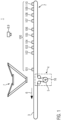
- Figure 2 Components of the device are made of Figure 1 shown in a schematic plan view from above.
- the dashed line represents a conceivable working area 12 of the handling device 7.
- the circular shape is merely exemplary and the working area 12 of the handling device 7 may have another suitable shape.
- Figure 2 Also visible are three storage positions: a first storage position 13, a second storage position 14, and a third storage position 15.
- the storage positions 13, 14, 15 can be part of the device 1 or part of another device, e.g., for transporting the objects moved to the respective storage position 13, 14, 15.
- the plurality of items 100 may comprise items 101 to 110.
- One or more of the items 101 to 110 for example in Figure 2 Objects 101, 102, 103, 104, 105, 107, 110 can be objects to be moved by the handling device 7.
- the remaining objects e.g. Figure 2 Objects 106, 108, 109 may not be objects that can be moved by the handling device 7.
- Objects that cannot be moved by the handling device 7 can, for example, be sorted out or, as will be explained in more detail later, by a second handling device 11 (see Figure 3 ) to be transferred.
- the storage positions 13, 14, 15 are in Figure 2 for illustration purposes, each labeled with the letters A, B, and C.
- Some of the objects 101 to 110 are also labeled with the letters A, B, and C for illustration purposes. This makes it clear, on the one hand, which objects are to be moved to which storage position. On the other hand, it makes it clear which of the objects 101 to 110 are to be moved by the handling device 7.
- the objects 101, 102, 103, 104, 105, 107, and 110 labeled with the letters A, B, and C can be moved by the handling device 7. The objects without letters cannot be moved by the handling device 7.
- a conveying distance 10 can be provided between each of the individual objects 101, 102, 103, 104, 105, 107, 110 to be moved, in particular by the handling device 7.
- the conveying distance detection unit 8 can be configured to detect each of the conveying distances 10.
- the device 1 can be configured to determine, based on a respective conveying distance 10, a movement speed and/or a movement acceleration with which the handling device 7 is to carry out a displacement.
- a conveying distance 10 can be provided between a first object to be moved, for example the object 101 in the Figure 2 , and a second object to be moved, e.g. the object 102 in the Figure 2 , can be used.
- the device 1 can be configured to determine a movement speed and/or a movement acceleration based on the conveying distance 10 determined (before the displacement of the object 101) between the first object 101 to be displaced and the second object 102 to be displaced.
- the handling device 7 can be configured to displace the second object 102 to be displaced at the determined movement speed and/or the determined movement acceleration.
- the first object to be moved can always be considered to be an object that is to be moved immediately before a second object to be moved. It should be clear that, depending on the situation, one and the same object can be considered to be the second and the first object one after the other.
- object 101 can be considered to be the first object and object 102 can be considered to be the second object.
- object 102 can be considered to be the first object and object 103 can be considered to be the second object, etc.
- the above explanations can therefore be applicable to the following displacements of the objects 103, 104, 105, 107, 110 to be moved by the handling device 7.
- the device can comprise a conveyor speed detection unit 16.
- the conveyor speed detection unit 16 can be configured to determine the conveyor speed 6 of the conveyor 2.
- the conveyor speed detection unit 16 can, as in Figure 1 shown by way of example, comprise a rotary encoder 16 on the drive roller 5 of the conveyor 2.
- the device 1 can be configured to determine the movement speed and/or the movement acceleration additionally based on the detected conveyor speed 6. This can mean that the device 1 can be configured to determine the movement speed and/or the movement acceleration based on the respectively determined conveyor distance 1 and the determined conveyor speed 6.
- the device 1 according to a further embodiment is similar in a schematic side view Figure 1 shown.
- the device 1 is according to the Figure 3 illustrated embodiment in a schematic plan view from above similar Figure 2 Compared to the one with reference to Figures 1 and 2
- the device 1 shown additionally has a second handling device 11.
- an exemplary second working area 17 of the second handling device 11 is shown by dashed lines.
- Figure 4 additional storage positions, namely a fourth storage position 18, a fifth storage position 19 and a sixth storage position 20, can be seen.
- the plurality of objects 100 can, as shown in the present embodiment, comprise the objects 111 to 120.
- the storage positions 13, 14, 15, 18, 19, 20 as well as the objects 111 to 120 to be moved by the first handling device 7 and the second handling device 11 are identified by letters A to F to illustrate the assignment of the respective objects to the respective storage positions.
- the device 1 according to the second embodiment can be configured to determine the movement speed and/or the movement acceleration separately for the first handling device 7 and the second handling device 11.
- only objects assigned to the respective handling device 7, 11 and/or conveying distances 10 between the objects assigned to the respective handling device 7, 11 can be taken into account.
- only objects 114 to 118 and 119 can be taken into account.
- only the objects 111 to 130 and 120 are taken into account when determining the movement speed and/or the movement acceleration of the second handling device 11.
Landscapes
- Engineering & Computer Science (AREA)
- Mechanical Engineering (AREA)
- Robotics (AREA)
- General Engineering & Computer Science (AREA)
- Manufacturing & Machinery (AREA)
- Quality & Reliability (AREA)
- Physics & Mathematics (AREA)
- General Physics & Mathematics (AREA)
- Automation & Control Theory (AREA)
- Manipulator (AREA)
Applications Claiming Priority (1)
| Application Number | Priority Date | Filing Date | Title |
|---|---|---|---|
| DE102023132582.5A DE102023132582A1 (de) | 2023-11-22 | 2023-11-22 | Vorrichtung und Verfahren zum Versetzen von Gegenständen |
Publications (1)
| Publication Number | Publication Date |
|---|---|
| EP4559637A1 true EP4559637A1 (fr) | 2025-05-28 |
Family
ID=93520585
Family Applications (1)
| Application Number | Title | Priority Date | Filing Date |
|---|---|---|---|
| EP24212284.4A Pending EP4559637A1 (fr) | 2023-11-22 | 2024-11-12 | Dispositif et procédé de déplacement d'objets |
Country Status (2)
| Country | Link |
|---|---|
| EP (1) | EP4559637A1 (fr) |
| DE (1) | DE102023132582A1 (fr) |
Citations (6)
| Publication number | Priority date | Publication date | Assignee | Title |
|---|---|---|---|---|
| EP1819994B2 (fr) | 2004-12-10 | 2018-03-28 | Scanvaegt International A/S | Procede et systeme d'etablissement de lots d'objets |
| JP2019030944A (ja) * | 2017-08-09 | 2019-02-28 | ファナック株式会社 | ロボットシステム |
| US20190225433A1 (en) * | 2018-01-25 | 2019-07-25 | Fanuc Corporation | Article transfer system and robot system |
| US20210101242A1 (en) * | 2019-10-04 | 2021-04-08 | Fanuc Corporation | Workpiece transfer system |
| CN109328173B (zh) * | 2016-06-23 | 2021-04-20 | 克朗斯股份公司 | 用于处理以至少一排依次运动的成件货物的方法和设备 |
| CN109249390B (zh) * | 2017-07-12 | 2021-04-23 | 发那科株式会社 | 机器人系统 |
Family Cites Families (4)
| Publication number | Priority date | Publication date | Assignee | Title |
|---|---|---|---|---|
| FR2936601B1 (fr) * | 2008-09-30 | 2011-02-11 | Arbor Sa | Procede de traitement d'objets en fonction de leurs poids individuels |
| DE102009060271A1 (de) * | 2009-12-23 | 2011-06-30 | Weber Maschinenbau GmbH Breidenbach, 35236 | Vorrichtung zum Umsetzen von Produkten |
| JP6659744B2 (ja) * | 2018-01-25 | 2020-03-04 | ファナック株式会社 | ロボットシステム |
| JP7368147B2 (ja) * | 2019-09-02 | 2023-10-24 | ファナック株式会社 | 搬送シミュレーション装置、及び搬送システム |
-
2023
- 2023-11-22 DE DE102023132582.5A patent/DE102023132582A1/de active Pending
-
2024
- 2024-11-12 EP EP24212284.4A patent/EP4559637A1/fr active Pending
Patent Citations (6)
| Publication number | Priority date | Publication date | Assignee | Title |
|---|---|---|---|---|
| EP1819994B2 (fr) | 2004-12-10 | 2018-03-28 | Scanvaegt International A/S | Procede et systeme d'etablissement de lots d'objets |
| CN109328173B (zh) * | 2016-06-23 | 2021-04-20 | 克朗斯股份公司 | 用于处理以至少一排依次运动的成件货物的方法和设备 |
| CN109249390B (zh) * | 2017-07-12 | 2021-04-23 | 发那科株式会社 | 机器人系统 |
| JP2019030944A (ja) * | 2017-08-09 | 2019-02-28 | ファナック株式会社 | ロボットシステム |
| US20190225433A1 (en) * | 2018-01-25 | 2019-07-25 | Fanuc Corporation | Article transfer system and robot system |
| US20210101242A1 (en) * | 2019-10-04 | 2021-04-08 | Fanuc Corporation | Workpiece transfer system |
Also Published As
| Publication number | Publication date |
|---|---|
| DE102023132582A1 (de) | 2025-05-22 |
Similar Documents
| Publication | Publication Date | Title |
|---|---|---|
| DE102018101375B4 (de) | Artikelbeförderungsvorrichtung, die mindestens einen Sensor nutzt | |
| EP3554972B1 (fr) | Dispositif et procédé de manutention de charges isolées déplacées les unes derrière les autres | |
| DE102018118556B4 (de) | Robotersystem | |
| EP2195267B2 (fr) | Procédé de désempilage de pièces en forme de plaques | |
| EP2112100B1 (fr) | Dispositif et procédé destinés au tri d'assemblages de marchandises au détail | |
| EP3428090B1 (fr) | Dispositif et procédé de manipulation des marchandises en mouvement dans au moins une rangée | |
| EP3694795B1 (fr) | Dispositif et procédé permettant la manutention de charges isolées déplacées en au moins trois rangées parallèles | |
| EP2952296A2 (fr) | Dispositif de prélèvement automatisé de pièces agencées dans un récipient | |
| EP3475198B1 (fr) | Procédé et dispositif permettant la manutention de marchandises de détail déplacées les unes derrière les autres en au moins une rangée | |
| DE102010022357A1 (de) | Roboteranordnung zum Befördern von Gegenständen | |
| EP3694794B1 (fr) | Dispositif et procédé de manipulation de marchandises arrangées en au moins deux rangées parallèles | |
| DE102020119556B4 (de) | Artikeltransportsystem mit mehreren beweglichen teilen | |
| EP3652092B1 (fr) | Procédé et dispositif de manipulation de marchandises de détail, d'articles et/ou d'emballages | |
| DE102019117349A1 (de) | Vorrichtung und Verfahren zum Umgang mit in mindestens einer Reihe nacheinander bewegten Stückgütern | |
| AT508863A2 (de) | Fördereinrichtung und verfahren zur ermittlung der reihenfolge von antrieben | |
| DE102017215320A1 (de) | Verfahren und Vorrichtung zum Umgang mit in mindestens einer Reihe hintereinander bewegten Stückgütern | |
| DE102016213396A1 (de) | Verfahren und Vorrichtung zum Umgang mit in mindestens einer Reihe hintereinander bewegten Stückgütern | |
| DE102017204997A1 (de) | Vorrichtung und Verfahren zum Umgang mit in mindestens einer Reihe bewegten Stückgütern | |
| DE102016119894A1 (de) | Robotische Transportvorrichtung zum Transportieren von Kleinteilen und mit der robotischen Vorrichtung durchführbares Verfahren | |
| DE102023132582A1 (de) | Vorrichtung und Verfahren zum Versetzen von Gegenständen | |
| EP1940711B1 (fr) | Dispositif et procede pour placer des piles d'objets plats sur des palettes | |
| DE102018132593A1 (de) | Vorrichtung und Verfahren zum Umgang mit in mindestens einer Reihe hintereinander bewegten Stückgütern | |
| DE102022134090B3 (de) | System und Verfahren zum automatisierten Transport von Produktionsgütern | |
| DE102016206659A1 (de) | Verfahren und Vorrichtung zum Umgang mit hintereinander bewegten Stückgütern | |
| EP3694796A1 (fr) | Arrangement et procédé de manutention de marchandises à la pièce déplacées dans au moins trois rangées |
Legal Events
| Date | Code | Title | Description |
|---|---|---|---|
| PUAI | Public reference made under article 153(3) epc to a published international application that has entered the european phase |
Free format text: ORIGINAL CODE: 0009012 |
|
| STAA | Information on the status of an ep patent application or granted ep patent |
Free format text: STATUS: THE APPLICATION HAS BEEN PUBLISHED |
|
| AK | Designated contracting states |
Kind code of ref document: A1 Designated state(s): AL AT BE BG CH CY CZ DE DK EE ES FI FR GB GR HR HU IE IS IT LI LT LU LV MC ME MK MT NL NO PL PT RO RS SE SI SK SM TR |
|
| STAA | Information on the status of an ep patent application or granted ep patent |
Free format text: STATUS: REQUEST FOR EXAMINATION WAS MADE |
|
| 17P | Request for examination filed |
Effective date: 20251128 |
|
| P01 | Opt-out of the competence of the unified patent court (upc) registered |
Free format text: CASE NUMBER: UPC_APP_0003874_4559637/2026 Effective date: 20260203 |