EP4559660A1 - Dispositif de chauffage et procédé de chauffage de préformes - Google Patents
Dispositif de chauffage et procédé de chauffage de préformes Download PDFInfo
- Publication number
- EP4559660A1 EP4559660A1 EP24215385.6A EP24215385A EP4559660A1 EP 4559660 A1 EP4559660 A1 EP 4559660A1 EP 24215385 A EP24215385 A EP 24215385A EP 4559660 A1 EP4559660 A1 EP 4559660A1
- Authority
- EP
- European Patent Office
- Prior art keywords
- heating
- transport
- pinion
- driver
- functional plane
- Prior art date
- Legal status (The legal status is an assumption and is not a legal conclusion. Google has not performed a legal analysis and makes no representation as to the accuracy of the status listed.)
- Pending
Links
Images




Classifications
-
- B—PERFORMING OPERATIONS; TRANSPORTING
- B29—WORKING OF PLASTICS; WORKING OF SUBSTANCES IN A PLASTIC STATE IN GENERAL
- B29C—SHAPING OR JOINING OF PLASTICS; SHAPING OF MATERIAL IN A PLASTIC STATE, NOT OTHERWISE PROVIDED FOR; AFTER-TREATMENT OF THE SHAPED PRODUCTS, e.g. REPAIRING
- B29C49/00—Blow-moulding, i.e. blowing a preform or parison to a desired shape within a mould; Apparatus therefor
- B29C49/42—Component parts, details or accessories; Auxiliary operations
- B29C49/4205—Handling means, e.g. transfer, loading or discharging means
- B29C49/42065—Means specially adapted for transporting preforms
-
- B—PERFORMING OPERATIONS; TRANSPORTING
- B29—WORKING OF PLASTICS; WORKING OF SUBSTANCES IN A PLASTIC STATE IN GENERAL
- B29C—SHAPING OR JOINING OF PLASTICS; SHAPING OF MATERIAL IN A PLASTIC STATE, NOT OTHERWISE PROVIDED FOR; AFTER-TREATMENT OF THE SHAPED PRODUCTS, e.g. REPAIRING
- B29C49/00—Blow-moulding, i.e. blowing a preform or parison to a desired shape within a mould; Apparatus therefor
- B29C49/42—Component parts, details or accessories; Auxiliary operations
- B29C49/4205—Handling means, e.g. transfer, loading or discharging means
- B29C49/42093—Transporting apparatus, e.g. slides, wheels or conveyors
-
- B—PERFORMING OPERATIONS; TRANSPORTING
- B29—WORKING OF PLASTICS; WORKING OF SUBSTANCES IN A PLASTIC STATE IN GENERAL
- B29C—SHAPING OR JOINING OF PLASTICS; SHAPING OF MATERIAL IN A PLASTIC STATE, NOT OTHERWISE PROVIDED FOR; AFTER-TREATMENT OF THE SHAPED PRODUCTS, e.g. REPAIRING
- B29C49/00—Blow-moulding, i.e. blowing a preform or parison to a desired shape within a mould; Apparatus therefor
- B29C49/42—Component parts, details or accessories; Auxiliary operations
- B29C49/64—Heating or cooling preforms, parisons or blown articles
- B29C49/68—Ovens specially adapted for heating preforms or parisons
- B29C49/685—Rotating the preform in relation to heating means
-
- B—PERFORMING OPERATIONS; TRANSPORTING
- B29—WORKING OF PLASTICS; WORKING OF SUBSTANCES IN A PLASTIC STATE IN GENERAL
- B29C—SHAPING OR JOINING OF PLASTICS; SHAPING OF MATERIAL IN A PLASTIC STATE, NOT OTHERWISE PROVIDED FOR; AFTER-TREATMENT OF THE SHAPED PRODUCTS, e.g. REPAIRING
- B29C2949/00—Indexing scheme relating to blow-moulding
- B29C2949/07—Preforms or parisons characterised by their configuration
- B29C2949/0715—Preforms or parisons characterised by their configuration the preform having one end closed
-
- B—PERFORMING OPERATIONS; TRANSPORTING
- B29—WORKING OF PLASTICS; WORKING OF SUBSTANCES IN A PLASTIC STATE IN GENERAL
- B29C—SHAPING OR JOINING OF PLASTICS; SHAPING OF MATERIAL IN A PLASTIC STATE, NOT OTHERWISE PROVIDED FOR; AFTER-TREATMENT OF THE SHAPED PRODUCTS, e.g. REPAIRING
- B29C49/00—Blow-moulding, i.e. blowing a preform or parison to a desired shape within a mould; Apparatus therefor
- B29C49/42—Component parts, details or accessories; Auxiliary operations
- B29C49/4205—Handling means, e.g. transfer, loading or discharging means
- B29C49/42073—Grippers
- B29C49/42085—Grippers holding inside the neck
Definitions
- the invention relates to a heating arrangement for preforms with a transport device for transporting the preforms from an input area to an output area along at least one heating section, with a plurality of transport units which can be rotated in a transport direction and which have a holder rotatable about a rotational axis for receiving a respective preform, a pinion rotatably coupled to the holder in a first functional plane, and a driver eccentric to the rotational axis in a second functional plane.
- the rotational position of the holder is continuously determined between the input area and the output area by at least one positive guide device coupled to the pinion and/or the driver.
- the positive guide device comprises at least one toothed rack which is arranged stationary along the heating section in the first functional plane on the transport device and which engages with the pinion, and at least one guide groove coupled to the driver.
- the invention relates to the technical field of blow molding, in particular stretch blow molding, for the production of plastic containers.
- preforms are first produced from a plastic material by an injection molding process, cooled, and temporarily stored before further processing.
- This process is particularly widespread for the production of containers (bottles, canisters, etc.) made of polyethylene terephthalate (PET). These are characterized by high mechanical stability and low weight.
- the movement of the transport units generally takes place in a horizontal plane that extends perpendicular to a vertical direction.
- the first functional plane refers to the height range over which the pinion extends. Elements arranged in this "plane" can interact with the pinion.
- the second functional plane also represents the height range in which engagement with the driver is possible.
- the transport direction refers to the (local) direction of movement of a transport unit at a specific position on the transport path.
- the rotational position refers to the relative positioning of the holder or a preform held therein to the local transport direction. Forced guidance then means that the rotational position and the relative rotation are predetermined during a transport movement.
- the preforms generally have a substantially round or rotationally symmetrical shape around a longitudinal axis. They form a wall made of the plastic material that encloses an interior space. This interior space initially does not yet have the shape and dimensions required for later use. It is accessible only via an access opening, which is often already provided with an injection-molded outer shape. This already has a neck section adapted to the later use and can, in particular, include a closure receptacle, a carrying handle, and/or a thread.
- the plastic material In order to bring the preform into its final shape, the plastic material must be heated above a suitable forming temperature, at least in the area of the wall defining the interior space. Depending on the wasted material, this is usually in the range of approximately 80°C to approximately 180°C. To achieve this temperature, the preforms are fed into a heating device, which is the basis of the invention. This can also be generally referred to as an "oven” or, after its central component, a "heating section.”
- preforms are generally continuously fed to the heating unit at their storage temperature (room temperature/ambient temperature) and transferred to the conveyor in the input area.
- the preforms are separated and successively placed into the holders of the conveyor units.
- the conveyor units then pass through at least one heating section before removing them from the holders in the output area and feeding them into the forming process.
- Heating sections each have heating elements which act on the preforms passing through this area. These are preferably arranged on both sides of the transport path, whereby designs with a single active heating element (infrared radiator) and an opposite arranged reflector or active heating elements arranged on both sides.
- the heated preforms are transferred to a forming machine as quickly as possible to avoid any temperature loss.
- This is typically a so-called blow molding machine or stretch blow molding machine.
- the tempered preforms are placed into an outer mold and then pressurized on the inside - in the interior area - by a fluid. This can particularly be air.
- a liquid in particular the product that will later be contained in the container, as the blowing fluid.
- the forming of the preform can be assisted by mechanical stress, in particular with a so-called stretch rod. This process is also referred to as the stretch blow molding process.
- Preform tempering can also have a spatial component. If containers with a non-circular cross-section—e.g., polygonal or oval—are to be produced from the preforms, the preforms must be heated unevenly before forming to achieve a sufficiently uniform container wall thickness. This process is also referred to as "preferential heating" (PH). In particular, the preforms are heated unevenly in the circumferential direction (around the longitudinal axis).
- preferential heating PH
- heating systems for the PH process have, at least in part, heating sections where no rotation of the preforms occurs. Heating elements arranged on one or both sides of the transport path ensure that the sides of the preforms facing these sides are heated more intensely than those perpendicular to them—i.e., in or against the transport direction.
- Such heating devices and heating methods have been known for some time.
- DE 10 2016 004 405 B4 a heating device for a PH process, in which in a first area the Preforms are rotated by a first drive belt meshing with a pinion and are held in a second area by a second toothed belt meshing with the pinion and running in the transport direction in a rotationally fixed manner - i.e. with a constant angle between the local transport direction and the orientation of the preforms.
- This allows an initial, uniform basic heating of the preforms all around, after which a specific temperature profile is imposed by a separate second heating section.
- the second toothed belt in order to switch from preferential heating to standard heating, can be moved at a speed which differs from the transport speed - i.e. in particular not at all or in the opposite direction to it.
- the resulting rotation of the preforms in the second area also leads to completely uniform heating, which is suitable for round containers.
- DE 10 2021 133 783 A1 a process in which in the second heating area it is possible to set a fixed rotational position of the preforms or to engage a drive for rotating the preforms in order to also be able to switch between preferential heating and standard heating.
- the DE 10 2022 100 090 A1 - from which the invention is based - it is proposed to predetermine the rotational movement or the rotation-free transport of the preforms between the input area and the output area by means of a mechanically controlled guide at each point.
- a mechanically controlled guide at each point.
- the invention is based on the object of providing a heating device for mechanically controlled pH heating that can be converted to standard heating mode with little effort. At the same time, the complex detection of preform orientation should be eliminated.
- At least one exchangeable area is formed—particularly in the heating area—in which a rack section meshing with the pinion in the first functional plane or a guide rail coupled to the driver in the second functional plane can be mounted alternatively.
- the interchangeable guide rail and rack section form a section of the positive-guiding device in the exchangeable area as alternatives to one another.
- This also allows a "positively guided" heating arrangement—in the exchangeable area—to be flexibly converted between "standard operation” and preferential heating.
- the heating device is not intended for operation without either of the two alternatives.
- a phase adjustment device is provided. This is designed to align the rotational position of all transport units located in the exchange area for (rotary) standard operation. This takes into account that the transport units in the exchange area are aligned in a certain orientation due to the previous PH operation. By correcting the rotational positions of all transport units in the exchange area, the heating device can then continue to operate seamlessly. This is particularly advantageous if the forced guidance is implemented not only between the input and output areas, but completely circumferentially. In this case, "catch curves" are generally not provided, which would transfer the rotational position from an indeterminate state to a defined phase position.
- the phase adjustment device is preferably designed as a template—i.e., as a mechanical alignment aid.
- This has an outer shape such that positioning in and/or displacement into the exchange area results in the transport units located therein being aligned. In particular, the positioning or displacement takes place in the second functional plane, resulting in an interaction between the outer shape and the drivers of the transport units located in the exchange area.
- the outer shape is preferably a so-called cycloid or trochoid.
- cycloid generally refer to the trajectory of points on a rolling element arranged eccentrically to its axis of rotation, which describe these points along the rolling path of the rolling element.
- cycloid is not to be understood in the strict mathematical sense, but rather functionally with reference to the present application. Since the driver in the first functional plane is not point-shaped, but rather occupies a two-dimensional surface, the term "cycloid” is also to be understood as a two-dimensional track in the first functional plane, which sweeps over a driver of a transport unit when its pinion is in phase with a rack and rolls along it.
- the guideway for the driver in a transfer area – where there is simultaneous engagement in the first functional plane and the second functional plane — must correspond to this shape, if necessary, with tolerances, to prevent blocking of the competing compulsory leadership.
- the template is particularly designed to align the drivers along the cycloid.
- the outer shape particularly preferably has a shape that corresponds to the edge curve of this (flat) cycloid. Tolerances in the range of a few millimeters can be taken into account.
- the phase adjustment device has an edge on one side, in particular a straight edge, corresponding to the course of the transport path in the exchange area.
- This edge is preferably arranged opposite a cycloid shape.
- the edge can be used to align all transport units in the exchange area uniformly – i.e., with an identical rotational position.
- This alignment aid can be used in two ways: On the one hand, all transport units can be aligned uniformly (to a dead center of the driver) by inserting them transversely to the transport direction.
- the template can also be used merely as a stop with which the individual drivers are brought into contact (manually or automatically).
- the phase adjustment device is preferably flat. It has a greater, in particular five times greater, extent in the transport direction and a transverse direction running transversely thereto in the horizontal plane than in the vertical direction perpendicular to both. Particularly preferably, the template has an extent of between 5 mm and 25 mm in the vertical direction.
- the template can be inserted into the exchange area in the second functional plane.
- guides are provided on the heating device, in particular, on which the template is held and can be inserted in the functional plane toward the drivers. This significantly simplifies alignment.
- the template may be connected to the rack section. These are connected in particular in such a way that the template is arranged in the second functional plane when the rack section is positioned in the first functional plane.
- the template comes into contact with the drivers in the exchange section before the engagement between the rack section and the pinions occurs.
- the exchange zone has a length in the transport direction that corresponds to an integer multiple of the rolling length of the pinion.
- the "rolling length” refers to the extent within which the pinion can completely roll once on an associated rack or rack section.
- the pinion and thus also the driver and the holder—performs a complete rotation around the rotation axis. Designing the exchange distance to be a multiple of the rolling length facilitates the conversion from a preferential heating configuration to a deterministic rotational movement and back. This ensures that the rotational position/phase position upon entry into the exchange zone is the same as upon exit—regardless of whether preferential heating or rotary heating operation is provided.
- the rack section does not extend beyond the replacement area. Rather, the rack section ends bluntly at the end of the replacement area without overlap. Once the rack section is removed from the second functional level, the pinion runs freely within the replacement area.
- the rack section is attached to the heating device in a positively guided manner. This makes it possible to move the rack section into a storage position after removal from the second functional plane.
- the positive guidance ensures that the rack is correctly positioned and aligned upon subsequent return to the second functional plane.
- the rack section is hingedly attached to the transport device by at least one pivot arm.
- the pivot arm is connected to the transport device so that it can rotate about a pivot axis running in a horizontal plane.
- the pivot axis runs parallel to the (local) transport direction in the exchange area.
- the rack section, the guide rail, and/or their mounts on the transport device are configured such that simultaneous installation in the exchange area is excluded.
- the guide rail is configured such that the rack section cannot be installed, in particular cannot be folded down, when the guide rail is inserted.
- the receiving space for the guide rail is inaccessible when the rack section is installed. This reliably prevents machine damage due to simultaneous, contradictory forced guidance.
- the guide rail and the rack section are mounted to the transport device using fastening means, in particular screws.
- fastening means in particular screws.
- the same fastening means and/or the same mountings for the fastening means can be used for both the rack section and the guide rail.
- the guide rail for PH operation is designed to be straight. This ensures that the position of the carrier in the transverse direction remains unchanged as it passes through the exchange area. This enables the maximum possible focus of the heating energy on the outer sides.
- the heating section has several exchange zones arranged one behind the other. These can preferably be directly adjacent to one another. In each of the several exchange zones, it is possible to locally remove a rack section from the first functional level and replace it with a guide rail in the second functional level - and vice versa. This allows for additional variability in the design of the heating process. For example, preferential heating can initially be provided in a first exchange zone, in order to then carry out a final, uniform heating of the outermost layer in a second exchange zone. It is also conceivable to initially provide conventional, circumferentially uniform heating in the first exchange zone when operating with a rack section and to implement PH guidance only in the second exchange zone.
- the convertible heating device comprises several heating sections along the transport path, one, several, or all of which are configured with one or more exchange zones, in each of which a rack section can be exchanged by a guide rail. This allows the heating device to be flexibly converted between standard heating mode and preferential heating in the exchange zones.
- the relative number and sequence of the different heating methods allows for even more diverse temperature profiles within the heated preform.
- the continuous forced guidance guarantees consistent and reproducible results.
- the PH in an upstream heating section or an upstream exchange section also has a defined effect on the temperature profile during removal in the output area, despite a downstream rotary heater.
- the heating device comprises at least one phase checking device. This is particularly preferably arranged at a position along the transport path in the region from the (first) exchange section to the output area.
- the phase verification device is designed to verify the correct phase position of the transport units—i.e., the correct, predetermined rotational adjustment at a given position along the transport path. If, despite the use of a phase adjustment device (template), one or more transport units are incorrectly positioned during changeover—for example, due to a geometric ambiguity in the relationship between the template curve and the possible positions of the respective driver—potentially catastrophic damage to the heating device or the forced guides can be prevented.
- a phase adjustment device template
- the phase check device can also be used to detect mispositioning for other reasons, such as wear on the pinion and/or rack.
- the phase check device is conveniently configured to trigger an emergency shutdown of the transport device, the heating arrangement, and, if applicable, any associated container forming device. It can therefore also be referred to as an "interruption switch.”
- a rotary forced guide i.e., an interaction between the pinion and an associated rack—is provided at the position of the phase-checking device.
- the phase-checking device preferably has a scanning curve that maps at least parts of a cycloid.
- the scanning curve is preferably arranged such that the driver of a correctly rotating transport unit with the correct phase position—i.e., during normal operation—rolls off without contact. If rotation is absent or is configured with a phase offset from the desired movement, the movement of the driver intersects the outer curve and thereby triggers the phase-checking device.
- the scanning curve is particularly preferably designed with a length which corresponds at least to a complete, in particular at least twice, the rolling length.
- error detection can be carried out on the basis of one or two complete unwindings, thus reducing the risk of not detecting incorrect positioning.
- the sensing curve is formed as the edge of a sensor, in particular a sheet-metal sensor.
- This sensor is arranged in the second functional plane with a sensing section forming the edge. Upon contact with a driver, the sensing section is displaced into or out of the second functional plane.
- the sensing section connects at an angle to a downward-running support section. Due to the sensing section's own weight, this is preloaded with a moment acting in the direction of the sensing curve. This moment must be overcome, especially when triggering the phase verification device.
- the sensor is pivoted (preferably on the support section) around a sensor pivot axis running parallel to the transport direction.
- a switch is configured to trigger the phase check device if the sensor position is left. This interrupts the movement within the transport device, allowing the error to be corrected and correct positioning to be achieved.
- the phase checking device is arranged in the region of the mountable and dismountable rack section. Most preferably, it is connected thereto in a functional unit and can be mounted and dismounted together.
- the pivot axis and the sensor pivot axis are particularly preferably aligned parallel to each other. This alignment makes it possible for the sensor to automatically orient itself in the sensing position when the rack section pivots out of the plane and then pivots back in, and to be removed from this position only upon contact with a driver.
- the positive guidance within the heating device according to the invention is completely effective between the input and output areas, so that in particular no "catching devices” are provided that transfer the transport units from an undefined rotational position to a defined rotational position. Rather, this rotational position is precisely defined throughout by the guidance of the driver and/or the engagement of the pinion – with mechanical tolerances.
- the invention also relates to a forming system for forming preforms into containers, comprising a preform feed and a container forming device, in particular a stretch blow molding machine.
- the preform feed is connected to the input area of a previously described heating device, the output area of which is connected to the container forming device. Due to the previously described inventive features, the heating device and thus the forming system can be particularly easily converted between conventional heating operation and preferential heating operation. This allows a wide range of round and non-round container shapes to be produced with the same machine.
- the container forming device comprises a plurality of forming stations, each with an outer mold.
- the forming stations are configured to introduce the heated preforms into the outer mold and form them therein by applying internal pressure.
- the outer molds are expediently interchangeable in order to adapt them to the desired shape of the container.
- the invention also relates to a method for at least partially converting a previously described heating arrangement or a forming system comprising the same. It is provided that the transport device is first brought to a standstill, if it is not already at a standstill. According to the invention, in order to convert the heating device in a replacement area, a guide rail is first removed from the second functional level, the transport units located in the replacement area are aligned, and then the rack section is mounted in the first functional level.
- the heating arrangement is thus Exchange area converted from preferential heating to standard heating operation.
- the transport device is also initially brought to a standstill, provided it is not already at a standstill.
- the rack is then removed from the first functional level, the drivers of the transport units located in the exchange section are then aligned and inserted into the guide rail, which is then attached to the transport device.
- the heating arrangement in the exchange section is thus converted from standard heating operation to preferential heating.
- the present invention makes it possible to utilize the advantages of a positively guided alignment of the preforms in a forming plant and at the same time to enable flexible switching between a standard heating operation and a PH operation.
- the alignment of the transport units is carried out with the aid of a previously described phase adjustment device. This allows the required alignment to be carried out quickly, reliably, and reproducibly.
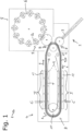
- the Fig. 1 shows schematically the general structure of a forming system 1 according to the invention, which is roughly divided into three sections:
- a preform feed 2 By means of a preform feed 2, individual preforms 3 are fed to a heating arrangement 4 according to the invention. This is set up to heat a continuous stream of preforms 3 and then feed them to a forming machine 5.
- the forming machine 5 has a plurality of blowing stations 7 arranged on the circumference of a so-called blowing wheel 6.
- the heated preforms 3 are formed by an internal pressure conveyed by a medium, in particular air, in accordance with the outer shape 7a formed by the blowing station 7.
- the heating arrangement 4 has a transport device 8, which is designed to transport the preforms 3 from an input area A to an output area B along a first heating section I and subsequently a second heating section II along a transport path T.
- the transport device 8 has an endlessly circulating chain of transport units 9, which are each designed to move an individual preform 3 along the transport path.
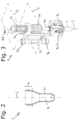
- the general structure of the preforms 3 is shown in the Fig. 2 These are essentially symmetrical about a longitudinal axis L.
- a wall 3a encloses an interior space 3b.
- This is connected to a Neck section 3c is accessible from the outside, which may deviate from a symmetry about the longitudinal axis L.
- the neck section 3c is designed with a screw thread for later use.
- the Fig. 3 shows the structure of a possible embodiment of a transport unit 9.
- This comprises a holder 9a for a preform 3, which can be rotated about a rotation axis r.
- the holder 9a has a mandrel which penetrates into the neck section 3c of the preform 3 and is supported on the inside thereof in a force-locking and/or friction-locking manner.
- Both the holder 9a and the transport unit 9 are sometimes referred to in the literature as "transport mandrels.”
- the rotation axis r is aligned with the longitudinal extension axis L of the preform 3.
- a rotational movement of the holder 9a is directly converted into a rotational movement of the preform 3.
- the transport unit 9 comprises a pinion 9b which is rotationally coupled to the holder 9a and arranged in a first functional plane F1 .
- the holder 9a and the pinion 9b are connected by means of a shaft 9c, at the upper end of which a driver 9d is arranged in a second functional plane F2 , also rotationally rigidly coupled.
- guide rollers 9e are also provided, which are rotatably mounted on a pin 9f running parallel to the rotation axis r.
- the pin 9f simultaneously serves as a connection to an adjacent transport unit 9 by engaging through an associated connection opening 9g.
- the endlessly circulating transport chain 10 formed by the plurality of transport units 9 is in the Fig. 1 only indicated schematically.
- the shaft 9c is mounted on the transport unit 9 so that it can move along the rotation axis r.
- the dead weight is held by a helical spring 9h, so that the holder 9a, with the edge portion 3a of the preform 3 held thereon, is positioned within a protective plate 9i. This serves to protect against unintentional heating.
- the transport chain 10 of transport units 9 is turned between the first heating section I and the second heating section II by a deflection wheel 11. Furthermore, heating devices 12 are schematically shown in both the first heating section I and the second heating section II, which act on the preforms 3 located in the respective heating section I, II. In the exemplary embodiment shown, heating devices 12 are provided both on the inside and on the outside. This ensures maximum flexibility with regard to heating operation in the first heating section I and/or in the second heating section II, since both are equally suitable for uniform standard heating operation and for non-uniform preferential heating operation.
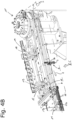
- Fig. 4A shows a perspective view of part of the transport device 8.
- the illustration is greatly simplified and limited to the essential aspects. Thus, only a single transport unit 9 of the circulating transport chain 10 is shown in order to better illustrate its interaction with the positive guidance device designed according to the invention.
- Fig. 4A shows a view of a part of the second heating section II. Part of this second heating section II is formed by the exchange area C according to the invention.
- the exchange area C is configured for preferential heating operation.
- a guide rail 13 with a linear guide groove 13a formed therein is provided in the second functional level F 2 .
- the driver 9d of the transport unit 9 engages in this guide rail, thereby determining the rotational position of the preform 3 and forcibly guiding it during movement along the transport path T.
- the figure also shows that the rotational position is also determined relative to the transport direction during rotation around the deflection wheel 11 by a guide rail 14 with a groove 14a arranged therein.
- This guide extends up to the guide rail 13 and, during transport, transfers the driver 9d directly into the guide groove 13a.
- the driver 9d Downstream, ie in the direction of the output area B, the driver 9d is transferred into a transformation rail 15, the guide groove of which has a first straight area 15a and a second curved area 15b, which partially has the shape of a cycloid. This converts the forced, rotationless movement into a continuous rotation, which is subsequently continued by a coupling between the pinion 9b and a rack 16 arranged in the first functional plane F1 .
- a phase checking device 17 is arranged on the rack 16, the function of which will be explained in more detail below.
- a rack section 18 is provided for the exchange area C, which is in the configuration according to the Figures 4A and 4B outside the first functional level F 1.
- the rack section 18 is hingedly mounted by means of two pivot arms 19 connected to the transport device 8 so as to pivot about a pivot axes a running along the transport path T.
- a second phase checking device 17 is also attached to the rack section 18.
- the Fig. 4C shows an alternative configuration of the transport device 8 from the Figures 4A and 4B .
- the guide rail 13 is removed from the second functional level F 2 and instead the rack section 18 is folded down into the first functional level F 1. This converts the forced guidance in the exchange area C to a rotary one.
- the transformation rail 15 has instead been moved to the area between the circulating rail 14 and the exchange area C. Its effect is monitored via the two phase checking devices 17.
- the guide rail 13 is removed from the area of the transport device 8 and is no longer a component thereof.
- FIGS 5A and 5B an alternative embodiment of the transport device 8 is shown.
- the figures refer exclusively to the second functional position, in which the rack section 18 in the first functional plane F 1 for a rotary Forced guides are provided.
- the conversion for PH operation is carried out analogously to the previously described embodiment.
- the Fig. 5A and 5B differs in that a phase adjustment device 20 in the form of a cycloid template is provided. Although this can also be used separately, in the illustrated embodiment it is firmly connected to the pivot arms 19 for the rack section 18. Thus, when the rack section 18 is pivoted downward, the respective transport units 9 are automatically adjusted to the correct phase position by mechanical contact between the phase adjustment device 20 and the respective drivers 9. The effect of this alignment is subsequently monitored by a phase checking device 17 in the area of the rack 16.
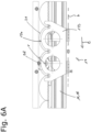
- phase checking devices 17 The function of the phase checking devices 17 is explained below by means of a comparative illustration of the Figures 6A and 6B explains:
- the Fig. 6A in a top view, schematically showing the course of normal operation.
- the center of the driver 9d follows a cycloid curve 21, so that its cross-sectional area sweeps over a cycloid surface.
Landscapes
- Engineering & Computer Science (AREA)
- Manufacturing & Machinery (AREA)
- Mechanical Engineering (AREA)
- Physics & Mathematics (AREA)
- Thermal Sciences (AREA)
- Blow-Moulding Or Thermoforming Of Plastics Or The Like (AREA)
Applications Claiming Priority (1)
| Application Number | Priority Date | Filing Date | Title |
|---|---|---|---|
| DE102023133036.5A DE102023133036A1 (de) | 2023-11-27 | 2023-11-27 | Heizeinrichtung und Verfahren zum Heizen von Vorformlingen |
Publications (1)
| Publication Number | Publication Date |
|---|---|
| EP4559660A1 true EP4559660A1 (fr) | 2025-05-28 |
Family
ID=93656161
Family Applications (1)
| Application Number | Title | Priority Date | Filing Date |
|---|---|---|---|
| EP24215385.6A Pending EP4559660A1 (fr) | 2023-11-27 | 2024-11-26 | Dispositif de chauffage et procédé de chauffage de préformes |
Country Status (2)
| Country | Link |
|---|---|
| EP (1) | EP4559660A1 (fr) |
| DE (1) | DE102023133036A1 (fr) |
Citations (3)
| Publication number | Priority date | Publication date | Assignee | Title |
|---|---|---|---|---|
| DE102016004405B4 (de) | 2016-04-14 | 2019-02-14 | Khs Corpoplast Gmbh | Heizvorrichtung und Verfahren zur thermischen Konditionierung von für die Blasformung vorgesehenen Vorformlingen |
| DE102021133783A1 (de) | 2021-12-20 | 2023-06-22 | Krones Aktiengesellschaft | Vorrichtung und Verfahren zum Herstellen von Kunststoffbehältnissen mit nicht kreisförmigen Querschnitten |
| DE102022100090A1 (de) | 2022-01-04 | 2023-07-06 | Khs Gmbh | Heizverfahren und Heizvorrichtung zur thermischen Konditionierung von Vorformlingen mit temperaturausgezeichneten Umfangsbereichen (preferential heating) |
Family Cites Families (1)
| Publication number | Priority date | Publication date | Assignee | Title |
|---|---|---|---|---|
| DE19757818A1 (de) * | 1997-12-24 | 1999-07-01 | Krupp Corpoplast Masch | Verfahren zur Temperierung von Vorformlingen sowie Vorrichtung zur Temperierung |
-
2023
- 2023-11-27 DE DE102023133036.5A patent/DE102023133036A1/de active Pending
-
2024
- 2024-11-26 EP EP24215385.6A patent/EP4559660A1/fr active Pending
Patent Citations (4)
| Publication number | Priority date | Publication date | Assignee | Title |
|---|---|---|---|---|
| DE102016004405B4 (de) | 2016-04-14 | 2019-02-14 | Khs Corpoplast Gmbh | Heizvorrichtung und Verfahren zur thermischen Konditionierung von für die Blasformung vorgesehenen Vorformlingen |
| DE102021133783A1 (de) | 2021-12-20 | 2023-06-22 | Krones Aktiengesellschaft | Vorrichtung und Verfahren zum Herstellen von Kunststoffbehältnissen mit nicht kreisförmigen Querschnitten |
| DE102022100090A1 (de) | 2022-01-04 | 2023-07-06 | Khs Gmbh | Heizverfahren und Heizvorrichtung zur thermischen Konditionierung von Vorformlingen mit temperaturausgezeichneten Umfangsbereichen (preferential heating) |
| EP4230381A1 (fr) * | 2022-01-04 | 2023-08-23 | KHS GmbH | Procédé de chauffage et dispositif de chauffage pour le conditionnement thermique de préformes avec des zones périphériques marquées par la température (preferential heating) |
Also Published As
| Publication number | Publication date |
|---|---|
| DE102023133036A1 (de) | 2025-05-28 |
Similar Documents
| Publication | Publication Date | Title |
|---|---|---|
| DE69406298T3 (de) | Vorrichtung zur herstellung von behältern aus kunststoff durch blasformen | |
| EP3284579B1 (fr) | Dispositif de chauffage pour une souffleuse comprenant un transporteur à chaîne pour un transport à deux rangées des préformes | |
| DE69110819T2 (de) | Spritzgiesssystem zum Herstellen einer hinterschnittenen Vorformung. | |
| EP2253452B1 (fr) | Dispositif et procédé d'équilibrage des températures de préformes en matière plastique | |
| DE69800629T2 (de) | Sternrad-förderer für vorformlingen oder behälter | |
| DE10325693B4 (de) | Transfervorrichtung für Gegenstände | |
| WO2016180510A1 (fr) | Procédé de thermorégulation non homogène de préformes | |
| EP4230381B1 (fr) | Procédé de chauffage et dispositif de chauffage pour le conditionnement thermique de préformes avec des zones périphériques marquées par la température | |
| EP2772342B1 (fr) | Parcours de chauffage pour ébauches | |
| EP2703322A1 (fr) | Dispositif de préhension de récipients | |
| EP3419807B1 (fr) | Dispositif de chauffage pour le conditionnement thermique de préformes destinées au moulage par soufflage | |
| EP2377667A2 (fr) | Dispositif et procédé destinés à la manipulation d'un produit dans un récipient | |
| DE3345226A1 (de) | Vorrichtung zum foliieren von flaschen mit einem zuschnitt | |
| DE2649630A1 (de) | Vorrichtung zum verschliessen und abdichten einer kartonpackung | |
| DE2429223A1 (de) | Kontinuierlich arbeitende rotationsvorrichtung zum formblasen von kunststoffhohlkoerpern | |
| EP2368692A2 (fr) | Dispositif de moulage par soufflage doté d'un mécanisme de verrouillage contrôlé | |
| EP1574460B1 (fr) | Dispositif de transport pour bouteilles ou récipients similaires | |
| DE102008063939A1 (de) | Blasform | |
| DE202008016838U1 (de) | Blasform | |
| EP3359367B1 (fr) | Dispositif et procédé pour mouler des préformes en matériau synthétique en récipients en matériau synthétique à l'aide d'un dispositif de couplage | |
| EP4245503A1 (fr) | Procédé et dispositif de fabrication de récipients en matière plastique à section non circulaire | |
| EP4559660A1 (fr) | Dispositif de chauffage et procédé de chauffage de préformes | |
| DE102012101239A1 (de) | Blasmaschine, transporteinrichtung und verfahren zum blasformen eines behälters mit der blasmaschine | |
| WO2018001778A1 (fr) | Dispositif de chauffage pour une machine de soufflage présentant une chaîne d'alimentation repliable | |
| DE19919956C1 (de) | Federwindeeinrichtung, insbesondere für Federwindemaschinen |
Legal Events
| Date | Code | Title | Description |
|---|---|---|---|
| PUAI | Public reference made under article 153(3) epc to a published international application that has entered the european phase |
Free format text: ORIGINAL CODE: 0009012 |
|
| STAA | Information on the status of an ep patent application or granted ep patent |
Free format text: STATUS: THE APPLICATION HAS BEEN PUBLISHED |
|
| AK | Designated contracting states |
Kind code of ref document: A1 Designated state(s): AL AT BE BG CH CY CZ DE DK EE ES FI FR GB GR HR HU IE IS IT LI LT LU LV MC ME MK MT NL NO PL PT RO RS SE SI SK SM TR |
|
| STAA | Information on the status of an ep patent application or granted ep patent |
Free format text: STATUS: REQUEST FOR EXAMINATION WAS MADE |
|
| 17P | Request for examination filed |
Effective date: 20251027 |
|
| P01 | Opt-out of the competence of the unified patent court (upc) registered |
Free format text: CASE NUMBER: UPC_APP_0014562_4559660/2025 Effective date: 20251125 |