EP4559745A1 - Kraftfahrzeug mit einem multifunktions-heckbereich und verfahren zur umwandlung eines fahrzeuginnenraums in einen schlafraum - Google Patents
Kraftfahrzeug mit einem multifunktions-heckbereich und verfahren zur umwandlung eines fahrzeuginnenraums in einen schlafraum Download PDFInfo
- Publication number
- EP4559745A1 EP4559745A1 EP24212958.3A EP24212958A EP4559745A1 EP 4559745 A1 EP4559745 A1 EP 4559745A1 EP 24212958 A EP24212958 A EP 24212958A EP 4559745 A1 EP4559745 A1 EP 4559745A1
- Authority
- EP
- European Patent Office
- Prior art keywords
- vehicle
- row
- rear shelf
- support
- seats
- Prior art date
- Legal status (The legal status is an assumption and is not a legal conclusion. Google has not performed a legal analysis and makes no representation as to the accuracy of the status listed.)
- Pending
Links
Images


Classifications
-
- B—PERFORMING OPERATIONS; TRANSPORTING
- B60—VEHICLES IN GENERAL
- B60R—VEHICLES, VEHICLE FITTINGS, OR VEHICLE PARTS, NOT OTHERWISE PROVIDED FOR
- B60R5/00—Compartments within vehicle body primarily intended or sufficiently spacious for trunks, suit-cases, or the like
- B60R5/04—Compartments within vehicle body primarily intended or sufficiently spacious for trunks, suit-cases, or the like arranged at rear of vehicle
- B60R5/044—Compartments within vehicle body primarily intended or sufficiently spacious for trunks, suit-cases, or the like arranged at rear of vehicle luggage covering means, e.g. parcel shelves
- B60R5/045—Compartments within vehicle body primarily intended or sufficiently spacious for trunks, suit-cases, or the like arranged at rear of vehicle luggage covering means, e.g. parcel shelves collapsible or transformable
-
- B—PERFORMING OPERATIONS; TRANSPORTING
- B60—VEHICLES IN GENERAL
- B60P—VEHICLES ADAPTED FOR LOAD TRANSPORTATION OR TO TRANSPORT, TO CARRY, OR TO COMPRISE SPECIAL LOADS OR OBJECTS
- B60P3/00—Vehicles adapted to transport, to carry or to comprise special loads or objects
- B60P3/32—Vehicles adapted to transport, to carry or to comprise special loads or objects comprising living accommodation for people, e.g. caravans, camping, or like vehicles
- B60P3/36—Auxiliary arrangements; Arrangements of living accommodation; Details
- B60P3/38—Sleeping arrangements, e.g. living or sleeping accommodation on the roof of the vehicle
- B60P3/39—Sleeping arrangements, e.g. living or sleeping accommodation on the roof of the vehicle expansible, collapsible or repositionable elements adapted to support a bed, e.g. wall portions
-
- B—PERFORMING OPERATIONS; TRANSPORTING
- B60—VEHICLES IN GENERAL
- B60N—SEATS SPECIALLY ADAPTED FOR VEHICLES; VEHICLE PASSENGER ACCOMMODATION NOT OTHERWISE PROVIDED FOR
- B60N2/00—Seats specially adapted for vehicles; Arrangement or mounting of seats in vehicles
- B60N2/24—Seats specially adapted for vehicles; Arrangement or mounting of seats in vehicles for particular purposes or particular vehicles
- B60N2/32—Seats specially adapted for vehicles; Arrangement or mounting of seats in vehicles for particular purposes or particular vehicles convertible for other use
- B60N2/34—Seats specially adapted for vehicles; Arrangement or mounting of seats in vehicles for particular purposes or particular vehicles convertible for other use into a bed
- B60N2/345—Seats specially adapted for vehicles; Arrangement or mounting of seats in vehicles for particular purposes or particular vehicles convertible for other use into a bed by adding parts
Definitions
- the present invention relates to the field of motor vehicles and in particular the transformation of a passenger compartment of a motor vehicle into a sleeping space.
- the objective of the present invention is to provide, from the design stage of the motor vehicle, the equipment necessary for transforming part of the passenger compartment into a sleeping area.
- the present invention relates to a motor vehicle comprising a floor extending in a plane comprising a longitudinal axis and a transverse axis, a passenger compartment comprising a first row of at least one seat and a second row of at least one seat spaced a longitudinal distance from the first row.
- the second row seat comprises a seat and a backrest articulated relative to the seat along a transverse articulation axis or transverse articulation between a position of use, in which the seat and the backrest form an angle of between 80° and 120° relative to each other and a folded position in which the backrest is close to the corresponding seat and extends along the longitudinal axis of the vehicle, preferably substantially parallel to the floor.
- the vehicle also includes a trunk space located behind the second row of seats.
- the vehicle includes a multi-function rear shelf configured to move from a storage position in which the rear shelf is secured to the vehicle and extends from an upper end of the backrest of the second row of seats along the longitudinal axis partly into the trunk space and a support position, in which, in the folded position of the second row of seats, the rear shelf extends in the longitudinal distance between the first and second rows of seats in the longitudinal continuity of an upper surface of the backrest of the second row of seats.
- the trunk space is accessible by the user once the vehicle's trunk door is open.
- the transverse articulation axis connecting the backrest and the seat base of the second row of seats is mounted in translation in a dedicated rail secured to the seat base and the backrest, so that when the backrest pivots around the transverse articulation axis, said transverse articulation axis moves vertically upwards along the vertical axis in particular to allow the backrest to adopt a position parallel to the longitudinal axis of the vehicle, i.e. as horizontal as possible.
- the longitudinal distance between the first and second row of seat(s) is between 15cm and 50cm.
- each seat of the first row of seats and/or the second row of seat(s) is mounted to slide along the longitudinal axis relative to the floor of the vehicle, for example in dedicated rails.
- the second row of seats may comprise a single seat delimiting two or three seats or comprise two or three parts each delimiting one or two seats.
- the vehicle further comprises a secondary floor secured to the motor vehicle in the storage position and in the support position and configured to move from the storage position, in which the secondary floor obstructs a housing in the floor of the vehicle, generally comprising accessories such as warning triangles, etc., and the support position, in which the secondary floor extends from the second row of seats partly into the trunk space in the longitudinal continuity of the upper surface of the backrest of said second row, on the side opposite the rear shelf.
- the main portion of the rear shelf, the rear surface of the backrests of the second row of seats and the secondary floor together form a flat support surface extending in the XY plane, substantially horizontal and configured to receive equipment, such as an additional mattress or bed base.
- the support surface is located at a height above the vehicle roof that is high enough to allow the user to sit without touching the roof.
- the vertical distance between the support surface and the vehicle roof is between 50cm and 1.50m. The goal is to be able to turn around or even move from a lying position on the back to lying on the stomach without having to get out of the vehicle.
- the support surface is located at a height below the vehicle openings to prevent accidental damage to said openings.
- the rear shelf comprises a substantially planar main portion delimited laterally by two transverse sides and two longitudinal sides and at least one part forming a support for the main portion in the support position.
- the transverse sides have, for example, a length greater than the length of the longitudinal sides, so as to give the main flat portion a rectangular shape.
- the dimension of the transverse sides and the longitudinal sides is preferably less than the dimension of the distance between the first and second rows of seats.
- the support-forming part in the support position, extends vertically, in a direction perpendicular to the main portion of the rear shelf and rests on the upper surface of the floor.
- the rear shelf comprises four support parts located at each corner of the main portion.
- the support-forming parts form support legs for the main portion.
- three support portions or a single support portion located in the center of the main portion could be provided.
- the longitudinal sides of the main portion of the rear shelf are integral with side walls of the trunk space, for example by fitting into a corresponding upper groove or guide rail provided in each side wall.
- the upper guide grooves extend along the longitudinal axis and are parallel to each other.
- the support portions in the storage position, extend vertically toward the roof of the vehicle and are configured to cooperate with vertical grooves in the side walls of the trunk space.
- the rear shelf is formed in a single piece, for example by plastic injection.
- the support parts are distinct from the main portion.
- said support parts are stored in a housing provided in the passenger compartment of the vehicle, for example on the floor or in a notch in the walls of the trunk space, and are assembled to the main portion, by fitting the end of each part into a corresponding notch of the main portion, to form a rear shelf in the support position.
- the support parts could also be made for the support parts to be attached to the main portion by a hinge in order to pivot said support parts from the storage position in which said parts are folded onto the main portion and the support position, in which said parts are deployed in a vertical position.
- the rear shelf is also configured to move from either the storage or support position to a use position, in which said rear shelf forms a table.
- the secondary floor is secured to the side walls of the trunk space, for example by fitting into a corresponding lower guide groove in each side wall.
- the secondary floor could include transverse lugs cooperating with lower complementary notches provided in the side walls of the trunk space in the supporting position.
- the vehicle further comprises a separation area secured to the motor vehicle and extending from the rear area towards the rear of the trunk space.
- the trunk space is not visible from outside the vehicle.
- the separation range comprises transverse lugs cooperating with complementary upper notches provided in the side walls of the trunk space.
- the rear shelf can be made of plastic material, for example provided on one of its faces with a honeycomb ribbing to combine finesse, structure and rigidity on the support surface.
- the rear shelf could be made of a metallic material, such as aluminum.
- the invention relates to a method for transforming the passenger compartment of a motor vehicle as described above, into a sleeping space.
- the method comprises a step of manipulating the secondary floor into the support position, in which the secondary floor extends from the second row of seats partly into the trunk space in the longitudinal continuity of the upper surface of the backrest of said second row, on the side opposite the rear shelf.
- the support parts are supported on the floor and the main portion extends between the first and second rows of seats.
- the secondary floor when handling the secondary floor, the secondary floor is fitted into the lower guide rails or grooves provided on the side walls of the trunk space.
- the lower guide grooves extend along the longitudinal axis and are parallel to each other.
- a preliminary step of detaching said separation area from the vehicle may be provided, by unclipping the corresponding upper rail lugs in the side walls of the trunk space and subsequent storage in the trunk space, for example under the secondary floor in the support position.
- a step could also be provided where the trunk volume is emptied by the user.
- Manipulating the rear shelf involves, for example, tipping the rear shelf so that the support portions extend downward from the main portion.
- the handling step comprises a step during which said support parts are fitted with the main portion.
- the manipulation step comprises a step during which said support parts are pivoted into the support position.
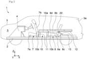
- THE figures 1 And 2 illustrate an example of a motor vehicle 1 comprising a floor 2 extending in an XY plane comprising the longitudinal axis X and the transverse axis Y of the vehicle and a body 3 delimiting the outline of the vehicle.
- the vehicle 1 notably comprises a front apron 4 delimiting an engine space 5 of a passenger compartment 6 of the vehicle.
- the passenger compartment 6 comprises a first row of seats 7, here a driver's seat and a front passenger seat and a second row of seat(s) 8 located to the rear of the first row of seats 7 and spaced apart by a longitudinal distance D1.
- the longitudinal distance D1 is between 15cm and 50cm.
- Each seat of the first row of seats 7 and/or the second row of seat(s) 8 is mounted to slide along the longitudinal axis relative to the floor 2 of the vehicle, for example in dedicated rails.
- the second row of seats 8 may comprise a single seat delimiting two or three seats or comprise two or three parts each delimiting one or two seats.
- Each seat 7, 8 comprises a seat 7a, 8a and a backrest 7b, 8b articulated relative to the corresponding seat 7a, 8a along a transverse articulation axis between a position of use, in which the seat and the backrest form an angle of between 80° and 120° relative to each other and a folded position in which the backrest is close to the corresponding seat.
- the seat(s) of the second row of seats 8 are configured so that, in the folded position, the backrest 8b extends along the longitudinal axis X of the vehicle, substantially parallel to the floor.
- the transverse articulation 8c connecting the backrest 8b and the seat 8a of the seat(s) of the second row of seats 8 is mounted in translation in a dedicated rail (not shown) secured to the seat 8a and the backrest 8b, so that when the backrest 8b pivots around the articulation 8c, the articulation 8c moves vertically upwards along the vertical axis Z to allow the backrest 8b to adopt a position parallel to the longitudinal axis X of the vehicle, i.e. as horizontal as possible.
- the horizontality of the 8b file depends on the horizontality of the road and the vehicle load.
- the vehicle 1 further comprises a trunk space 9 located at the rear of the second row of seat(s) 8 and accessible by the user once the trunk door 3a of the vehicle is open.
- the vehicle 1 further comprises a rear shelf 10 secured to the vehicle 1 in a storage position.
- the rear shelf 10 is configured to move from the storage position, visible on the figures 1 And 3 , in which the rear shelf 10 extends partly into the trunk space 9 and a support position, visible on the figures 2 And 4 , in which, in the folded position of the second row of seat(s) 8, the rear shelf 10 extends between the first and second row of seats 7, 8 in the longitudinal continuity of the upper surface 8d of the backrests of the second row of seats 8.
- the rear shelf 10 In the storage position, visible on the Figure 1 , the rear shelf 10 extending from an upper end of the backrests 8b of the second row of seat(s) 8 along the longitudinal axis X towards the rear of the vehicle and partly covering the trunk space 9.
- the rear beach 10 comprises a main flat portion 10a delimited laterally by two transverse sides 10b and two longitudinal sides 10c.
- the transverse sides 10b have a length greater than the length of the longitudinal sides 10c, so as to give the main flat portion 10a a rectangular shape.
- the longitudinal dimension of the longitudinal sides 10c is less than the longitudinal distance D1 between the first and second row of seats 7, 8.
- the longitudinal sides 10c of the rear shelf 10 are integral with the side walls 9a of the trunk space 9, here by fitting into a corresponding upper guide groove 9b in each side wall 9a.
- the rear shelf 10 further comprises parts 11 forming support for the main portion 10a in the support position, visible in the Figure 2 .
- each support portion 11 extends vertically, in a direction perpendicular to the main portion 10a of the rear shelf and rests on the upper surface of the floor 2.
- the rear shelf 10 comprises four support portions 11 located at each corner of the main portion 10a.
- three support parts 11 or a single support part 11 located in the center of the main portion 10a could be provided.
- the support portions 11 form support feet for the main portion 10a.
- the support portions 11 extend vertically toward the roof of the vehicle.
- Vertical grooves could be provided in the side walls 9a of the trunk space 9, each intended to receive a support portion 11.
- the rear shelf 10 is here formed in a single piece, for example by plastic injection.
- the support-forming parts 11 are separate from the main portion 10a and stored in a housing (not shown) provided in the passenger compartment of the vehicle, for example on the floor or in a notch in the walls of the trunk space, and are assembled to the main portion 10a, by fitting the end of each part 11 into a corresponding notch of the main portion 10a, to form a rear shelf in the support position.
- the support parts 11 are distinct from the main portion 10a and fixed to the main portion 10a by an articulation (not shown) in order to pivot said support parts 11 from the storage position in which said parts 11 are folded onto the main portion 10a and the support position, in which said parts 11 are deployed in a vertical position.
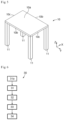
- the rear shelf 10 is also configured to move from either the storage or support position to a use position, in which said rear shelf forms a table, as illustrated in the Figure 5 .
- the motor vehicle 1 further comprises a secondary floor 12 secured to the motor vehicle in the storage position and in the support position.
- the secondary floor 12 is configured to move from the storage position, visible on the figures 1 And 3 , in which the secondary floor 12 obstructs a housing (not shown) provided in the floor 2 of the vehicle, generally comprising accessories such as warning triangles, etc., and a support position, visible on the figures 2 And 4 , in which, in the folded position of the second row of seat(s) 8, the secondary floor 12 extends from the second row of seats 8 partly into the trunk space 9 in the longitudinal continuity of the upper surface 8d of the backrests of the second row of seats 8.
- the main portion 10a of the rear shelf 10, the upper surface 8d of the backrests 8b of the second row of seats 8 and the secondary floor 12 together form a flat support surface extending in the XY plane, substantially horizontal, configured to receive equipment, such as a mattress 20 or an additional bed base.
- the support surface is located at a height above the vehicle roof that is high enough to allow the user to sit without touching the roof.
- the distance between the support surface and the vehicle roof is between 50cm and 1.50m.
- the support surface is located at a height below the openings (not shown) of the vehicle in order to avoid any accidental damage to said openings.
- the secondary floor 12 is here secured to the side walls 9a of the trunk space 9, here by fitting into a corresponding lower guide groove 9c in each side wall 9a.
- the secondary floor 12 comprises transverse lugs cooperating with lower complementary notches provided in the side walls 9a of the trunk space 9 in the support position.
- the motor vehicle 1 further comprises a separation area 13 secured to the motor vehicle in the storage position.
- the partition 13 extends from the rear shelf 10 towards the rear of the trunk 9.
- the trunk space 9 is not visible from outside the vehicle.
- the separation area 13 comprises transverse lugs 13a cooperating with the upper rail 9b provided in the side walls 9a of the trunk space.
- the lugs 13a of the separation area 13 cooperate with upper complementary notches provided in the side walls 9a of the trunk space 9 and distinct from the rail 9b.
- the rear shelf 10 may be made of plastic material, for example provided on one of its faces with a honeycomb ribbing to combine finesse, structure and rigidity on the support surface.
- the rear shelf 10 could be made of a metallic material, such as, for example, aluminum.
- FIG. 6 illustrates the steps of a method 30 for transforming the passenger compartment 6 of the vehicle 1 into a sleeping space.
- the rear shelf 10 is separated from the vehicle by unclipping the main portion 10a and/or the support-forming parts 11 from the side walls 9a of the trunk space 9.
- a preliminary step 31a of detaching said separation area 13 from the vehicle may be provided, by unclipping the lugs 13a of the corresponding upper guide rail 9b in the side walls 9a of the trunk space 9 and subsequent storage in the trunk space 9, for example under the secondary floor 12 in the support position.
- a step could also be provided where the trunk volume is emptied by the user.
- the method 30 further comprises a step 32 during which the second row of seat(s) 8 is tilted into the folded position in which the backrest is close to the corresponding seat and in which the backrest 8b extends along the longitudinal axis X of the vehicle, substantially parallel to the floor 2.
- the rear shelf 10 is then manipulated, during step 33, to find itself in the support position, in which the support-forming parts 11 are supported on the floor 2 and the main portion 10a extends between the first and second row of seats 7, 8.
- step 32 of tilting the second row of seat(s) 8 could be provided after the step of manipulating the rear shelf 10.
- Manipulating the rear shelf 10 in the illustrated embodiment, consists of reversing the rear shelf 10 so that the support parts 11 extend from the main portion 10a downwards.
- the handling step comprises a step during which said support-forming parts 11 are fitted with the main portion 10a.
- the manipulation step comprises a step during which said support parts 11 are pivoted into the support position.
- the method 30 further comprises a step 34 during which the secondary floor 12 is manipulated to fit it into the lower guide grooves 9c.
Landscapes
- Engineering & Computer Science (AREA)
- Mechanical Engineering (AREA)
- Health & Medical Sciences (AREA)
- Public Health (AREA)
- Transportation (AREA)
- Vehicle Step Arrangements And Article Storage (AREA)
Applications Claiming Priority (1)
| Application Number | Priority Date | Filing Date | Title |
|---|---|---|---|
| FR2313125A FR3155762A1 (fr) | 2023-11-27 | 2023-11-27 | Véhicule automobile comprenant une plage arrière multifonction et procédé de transformation d’un habitacle du véhicule en espace de couchage |
Publications (1)
| Publication Number | Publication Date |
|---|---|
| EP4559745A1 true EP4559745A1 (de) | 2025-05-28 |
Family
ID=90362959
Family Applications (1)
| Application Number | Title | Priority Date | Filing Date |
|---|---|---|---|
| EP24212958.3A Pending EP4559745A1 (de) | 2023-11-27 | 2024-11-14 | Kraftfahrzeug mit einem multifunktions-heckbereich und verfahren zur umwandlung eines fahrzeuginnenraums in einen schlafraum |
Country Status (2)
| Country | Link |
|---|---|
| EP (1) | EP4559745A1 (de) |
| FR (1) | FR3155762A1 (de) |
Citations (12)
| Publication number | Priority date | Publication date | Assignee | Title |
|---|---|---|---|---|
| US4443034A (en) * | 1981-08-17 | 1984-04-17 | Mechanical Plastics Corp. | Folding platform and shelves for use in vehicles |
| JPS59183713A (ja) * | 1983-04-04 | 1984-10-18 | アイシン精機株式会社 | 車輛のシ−ト艤装装置 |
| JPS60145950U (ja) * | 1984-03-12 | 1985-09-27 | 日産自動車株式会社 | 椅子・テ−ブル兼用トノボ−ド |
| JPS649851U (de) * | 1987-07-07 | 1989-01-19 | ||
| JPH0735191U (ja) * | 1993-12-13 | 1995-06-27 | 盟和産業株式会社 | 自動車の後部棚構造 |
| JPH09104271A (ja) * | 1995-10-11 | 1997-04-22 | Central Motor Co Ltd | フラットデッキ構造 |
| JPH09164885A (ja) * | 1995-12-15 | 1997-06-24 | Daihatsu Motor Co Ltd | 自動車用デッキボードの構造 |
| JP2000108747A (ja) * | 1998-10-07 | 2000-04-18 | Fuji Heavy Ind Ltd | 車両の後席シート構造 |
| JP2003165467A (ja) * | 2001-12-03 | 2003-06-10 | Nissan Motor Co Ltd | 車両用フロアボード構造 |
| US6702355B1 (en) * | 2002-10-09 | 2004-03-09 | General Motors Corporation | Multi-function security shade panel for a vehicle |
| JP2010105470A (ja) * | 2008-10-29 | 2010-05-13 | Mazda Motor Corp | 車両の後部荷室構造 |
| US20210309132A1 (en) * | 2020-04-02 | 2021-10-07 | Andras Plank S. | Vehicular Camp and Method |
-
2023
- 2023-11-27 FR FR2313125A patent/FR3155762A1/fr active Pending
-
2024
- 2024-11-14 EP EP24212958.3A patent/EP4559745A1/de active Pending
Patent Citations (12)
| Publication number | Priority date | Publication date | Assignee | Title |
|---|---|---|---|---|
| US4443034A (en) * | 1981-08-17 | 1984-04-17 | Mechanical Plastics Corp. | Folding platform and shelves for use in vehicles |
| JPS59183713A (ja) * | 1983-04-04 | 1984-10-18 | アイシン精機株式会社 | 車輛のシ−ト艤装装置 |
| JPS60145950U (ja) * | 1984-03-12 | 1985-09-27 | 日産自動車株式会社 | 椅子・テ−ブル兼用トノボ−ド |
| JPS649851U (de) * | 1987-07-07 | 1989-01-19 | ||
| JPH0735191U (ja) * | 1993-12-13 | 1995-06-27 | 盟和産業株式会社 | 自動車の後部棚構造 |
| JPH09104271A (ja) * | 1995-10-11 | 1997-04-22 | Central Motor Co Ltd | フラットデッキ構造 |
| JPH09164885A (ja) * | 1995-12-15 | 1997-06-24 | Daihatsu Motor Co Ltd | 自動車用デッキボードの構造 |
| JP2000108747A (ja) * | 1998-10-07 | 2000-04-18 | Fuji Heavy Ind Ltd | 車両の後席シート構造 |
| JP2003165467A (ja) * | 2001-12-03 | 2003-06-10 | Nissan Motor Co Ltd | 車両用フロアボード構造 |
| US6702355B1 (en) * | 2002-10-09 | 2004-03-09 | General Motors Corporation | Multi-function security shade panel for a vehicle |
| JP2010105470A (ja) * | 2008-10-29 | 2010-05-13 | Mazda Motor Corp | 車両の後部荷室構造 |
| US20210309132A1 (en) * | 2020-04-02 | 2021-10-07 | Andras Plank S. | Vehicular Camp and Method |
Also Published As
| Publication number | Publication date |
|---|---|
| FR3155762A1 (fr) | 2025-05-30 |
Similar Documents
| Publication | Publication Date | Title |
|---|---|---|
| FR2828459A1 (fr) | Tablette arriere pour vehicule | |
| FR2828137A1 (fr) | Systeme de toit rigide retractable pour vehicule automobile | |
| FR2785243A1 (fr) | Agencement d'un coffre de vehicule automobile | |
| EP4559745A1 (de) | Kraftfahrzeug mit einem multifunktions-heckbereich und verfahren zur umwandlung eines fahrzeuginnenraums in einen schlafraum | |
| FR2918935A3 (fr) | Vehicule automobile comprenant un siege arriere depliable | |
| FR2863963A1 (fr) | Siege pour vehicule | |
| FR2921309A1 (fr) | Tablette amovible multifonctions pour planche de bord, planche de bord pour une telle tablette et vehicule automobile comprenant une telle planche de bord equipee d'au moins une telle tablette | |
| EP1211128B1 (de) | Sitzanordnung für Kraftfahrzeuge | |
| FR3155763A1 (fr) | Véhicule automobile comprenant une plage arrière multifonction et procédé de transformation d’un habitacle du véhicule en espace de couchage | |
| FR2911307A3 (fr) | Agencement de siege depliable et repliable pour vehicule automobile | |
| FR3117074A1 (fr) | Dispositif de support a tablette mobile multi positions et module de rangement equipe d’un tel dispositif | |
| EP4171999B1 (de) | Kraftfahrzeug mit einer optimierten stauraumanordnung im armaturenbrett | |
| FR2966096A1 (fr) | Siege escamotable pour vehicule automobile | |
| EP1807284B1 (de) | Kraftfahrzeug mit einer mit einem verstaubaren tablett versehenen seitentür | |
| WO2016020597A1 (fr) | Siege escamotable de vehicule automobile | |
| EP1211125A1 (de) | Sitzeinheitanordnung im Innenraum eines Kraftfahrzeuges | |
| FR2891509A1 (fr) | Siege de vehicule automobile dont le dossier comporte un bac de rangement et une tablette mobile. | |
| EP3532341B1 (de) | Modularer sitz für ein kraftfahrzeug | |
| FR3063697A1 (fr) | Cloison de protection pour un vehicule automobile utilitaire | |
| EP2877389B1 (de) | Element einer fahrgestellplattform eines kraftfahrzeuges , fahrgestell und damit ausgestattetes kraftfahrzeug | |
| FR3142739A1 (fr) | Dispositif d’extension de benne pour vehicule automobile avec ridelle arriere | |
| FR2907397A1 (fr) | Amenagement interieur d'un vehicule automobile comprenant deux tablettes escamotables. | |
| FR2958234A3 (fr) | Dispositif de cloisonnement d'un coffre de vehicule automobile du type comportant une cloison de separation sur laquelle est montee a rotation une partie d'une tablette arriere | |
| FR3142740A1 (fr) | Dispositif d’extension de benne pour vehicule automobile avec ridelle arriere | |
| FR3167090A1 (fr) | Siège intégré à une cloison d’arrêt de chargement. |
Legal Events
| Date | Code | Title | Description |
|---|---|---|---|
| PUAI | Public reference made under article 153(3) epc to a published international application that has entered the european phase |
Free format text: ORIGINAL CODE: 0009012 |
|
| STAA | Information on the status of an ep patent application or granted ep patent |
Free format text: STATUS: THE APPLICATION HAS BEEN PUBLISHED |
|
| AK | Designated contracting states |
Kind code of ref document: A1 Designated state(s): AL AT BE BG CH CY CZ DE DK EE ES FI FR GB GR HR HU IE IS IT LI LT LU LV MC ME MK MT NL NO PL PT RO RS SE SI SK SM TR |
|
| STAA | Information on the status of an ep patent application or granted ep patent |
Free format text: STATUS: REQUEST FOR EXAMINATION WAS MADE |
|
| 17P | Request for examination filed |
Effective date: 20251212 |
|
| STAA | Information on the status of an ep patent application or granted ep patent |
Free format text: STATUS: EXAMINATION IS IN PROGRESS |
|
| 17Q | First examination report despatched |
Effective date: 20260126 |