EP4559802A1 - Seitenschubvorrichtung - Google Patents
Seitenschubvorrichtung Download PDFInfo
- Publication number
- EP4559802A1 EP4559802A1 EP23842709.0A EP23842709A EP4559802A1 EP 4559802 A1 EP4559802 A1 EP 4559802A1 EP 23842709 A EP23842709 A EP 23842709A EP 4559802 A1 EP4559802 A1 EP 4559802A1
- Authority
- EP
- European Patent Office
- Prior art keywords
- tunnel
- slit holes
- propeller
- slit
- side thruster
- Prior art date
- Legal status (The legal status is an assumption and is not a legal conclusion. Google has not performed a legal analysis and makes no representation as to the accuracy of the status listed.)
- Pending
Links
Images


Classifications
-
- B—PERFORMING OPERATIONS; TRANSPORTING
- B63—SHIPS OR OTHER WATERBORNE VESSELS; RELATED EQUIPMENT
- B63H—MARINE PROPULSION OR STEERING
- B63H25/00—Steering; Slowing-down otherwise than by use of propulsive elements; Dynamic anchoring, i.e. positioning vessels by means of main or auxiliary propulsive elements
- B63H25/42—Steering or dynamic anchoring by propulsive elements; Steering or dynamic anchoring by propellers used therefor only; Steering or dynamic anchoring by rudders carrying propellers
-
- B—PERFORMING OPERATIONS; TRANSPORTING
- B63—SHIPS OR OTHER WATERBORNE VESSELS; RELATED EQUIPMENT
- B63H—MARINE PROPULSION OR STEERING
- B63H25/00—Steering; Slowing-down otherwise than by use of propulsive elements; Dynamic anchoring, i.e. positioning vessels by means of main or auxiliary propulsive elements
- B63H25/46—Steering or dynamic anchoring by jets or by rudders carrying jets
-
- B—PERFORMING OPERATIONS; TRANSPORTING
- B63—SHIPS OR OTHER WATERBORNE VESSELS; RELATED EQUIPMENT
- B63H—MARINE PROPULSION OR STEERING
- B63H25/00—Steering; Slowing-down otherwise than by use of propulsive elements; Dynamic anchoring, i.e. positioning vessels by means of main or auxiliary propulsive elements
- B63H25/42—Steering or dynamic anchoring by propulsive elements; Steering or dynamic anchoring by propellers used therefor only; Steering or dynamic anchoring by rudders carrying propellers
- B63H2025/425—Propulsive elements, other than jets, substantially used for steering or dynamic anchoring only, with means for retracting, or otherwise moving to a rest position outside the water flow around the hull
Definitions
- the present disclosure relates to side thruster equipment that applies propulsive force to a ship in a hull width direction.
- some ships include a side thruster that applies propulsive force in a hull width direction.
- the side thruster includes a controllable pitch propeller including flat blades.
- An incidence angle of a fluid at a blade leading edge of the flat blade is larger than that of a blade having a curved blade section. Therefore, a leading edge load increases, and a leading edge separation easily occurs.
- the flat blade since the flat blade has no twist, the load increases toward a blade tip end, and a pressure difference between a pressure surface and suction surface of a blade tip becomes large. Therefore, a large-scale blade tip leakage vortex is easily generated.
- the side thruster including the flat blades there is a problem that cavitation is easily generated due to a low-pressure region around the blade.
- a side thruster including a controllable pitch propeller includes a jet mechanism that can increase the speed of water flow from an upstream side of the water flow at a blade peripheral edge position.
- a pressure water channel is located outside a tunnel at which the controllable pitch propeller is located, and injection holes connected to the pressure water channel are located annularly along a peripheral surface of the tunnel. Then, sea water in the pressure water channel is jetted from the injection holes to upstream surfaces of the blades by the driving of a pressurization impeller.
- the angle of attack with respect to the water flow in the blade section decreases, and therefore, an extreme overload at the blade tip end is prevented.
- the generation of the cavitation is suppressed.
- the pressurization impeller and a driving device that drives the pressurization impeller are required. This makes the structure complex and increases the manufacturing cost.
- the present disclosure was made to solve the above problems, and an object of the present disclosure is to provide side thruster equipment that can suppress the generation of cavitation by a simple structure.
- side thruster equipment includes: a cylindrical tunnel extending in a width direction of a hull; a propeller including flat blades and located at a predetermined position in the tunnel such that a rotation axis of the propeller coincides with a central axis of the tunnel; first slit holes located on a portion of a wall of the tunnel, which is closer to starboard than the propeller, so as to be lined up in a circumferential direction of the tunnel, the first slit holes being openings each located so as to extend in a direction intersecting with an extending direction of the tunnel; second slit holes located on a portion of the wall of the tunnel, which is closer to port than the propeller, so as to be lined up in the circumferential direction of the tunnel, the second slit holes being openings each located so as to extend in a direction intersecting with the extending direction of the tunnel; and a return channel that is a tubular channel located such that the tunnel penetrates an inside of the tubular
- the present disclosure achieves an effect of being able to provide side thruster equipment that has the above-described configuration and can suppress the generation of cavitation by a simple structure.
- FIG. 1 is a schematic sectional view of a portion of a hull at which side thruster equipment as one example of the present embodiment is located.
- FIG. 2 is a schematic diagram showing one example of slit holes that are open on a wall of a tunnel. In FIG. 2 , the thickness of a wall 21 of the tunnel is ignored.
- side thruster equipment 100 shown in FIG. 1 is located at a bow side or stern side of a hull 1.
- the side thruster equipment 100 includes: a cylindrical tunnel 2 extending in a width direction of the hull 1; a side thruster 3; first slit holes S1 and second slit holes S2 as opening portions that are open on the wall 21 of the tunnel 2; and a tubular return channel 7.
- the tunnel 2 is located at the bow side or stern side of the hull 1 and under a waterline so as to penetrate the hull 1 in a hull width direction.
- the side thruster 3 is a thruster that applies propulsive force to the hull 1 in the hull width direction by sucking water, such as sea water, from one of openings of the tunnel 2 and discharging the water from the other opening.
- the side thruster 3 includes: a propeller 4; a motor 5 that drives the propeller 4; a gear case 6 accommodating a power transmitter that transmits the output of the motor 5 to the propeller 4; and the like.
- the propeller 4 is located at a predetermined position in the tunnel 2 such that a rotation axis of the propeller 4 coincides with a central axis A of the tunnel 2.
- the propeller 4 is a controllable pitch propeller including flat blades 41.
- the direction of the water flow in the tunnel 2 which is generated by the rotation of the propeller 4 can be changed by changing a blade angle.
- the propeller 4 includes four flat blades 41.
- the first slit holes S1 and the second slit holes S2 are located so as to sandwich the propeller 4 and be lined up in a circumferential direction of the tunnel 2 on portions of the wall 21 which are located at both sides of the propeller 4.
- the first slit holes S1 are located at the portion of the wall 21 which is closer to the starboard than the propeller 4, and the second slit holes S2 are located at the portion of the wall 21 which is closer to the port than the propeller 4.
- the first slit holes S1 and the second slit holes S2 are openings that are located so as to extend in respective directions intersecting with an extending direction of the tunnel 2.
- the return channel 7 is a tubular channel located such that the tunnel 2 penetrates an inside of of the tubular tunnel.
- the return channel 7 communicates with the inside of the tunnel 2 through the slit holes S1 and S2 located at both sides of the return channel 7.
- the return channel 7 is formed by a gap between the tubular wall 21 defining the tunnel 2 and a tubular wall 22 located outside the wall 21 with a predetermined interval.
- each first slit hole S1 and each second slit hole S2 are located so as to extend in respective directions that intersect with the circumferential direction of the tunnel 2 in opposite directions. Moreover, when viewed in the extending direction of the tunnel 2, the first slit holes S1 are located so as to be continuous over the entire periphery of the tunnel 2. Similarly, when viewed in the extending direction of the tunnel 2, the second slit holes S2 are located so as to be continuous over the entire periphery of the tunnel 2. In other words, when viewed in the extending direction of the tunnel 2, there is no gap between the adjacent first slit holes S1, and similarly, there is no gap between the adjacent second slit holes S2.
- the adjacent first slit holes S1 when viewed in the extending direction of the tunnel 2, partially overlap each other as shown by an overlapping range D1 in FIG. 2 , and the adjacent second slit holes S2 partially overlap each other as shown by an overlapping range D2 in FIG. 2 .
- FIG. 1 shows an example in which as shown by solid line arrows, water flows in the tunnel 2 from the port side to the starboard side by the rotation of the propeller 4. At a downstream side of the propeller 4, the water flows as swirling flow. Then, by the water flow in the tunnel 2 which is generated by the rotation of the propeller 4, water pressure applied to the first slit holes S1 located downstream of the propeller 4 becomes higher than water pressure applied to the second slit holes S2 located upstream of the propeller 4.
- FIG. 1 shows an example in which as shown by solid line arrows, water flows in the tunnel 2 from the port side to the starboard side by the rotation of the propeller 4. At a downstream side of the propeller 4, the water flows as swirling flow. Then, by the water flow in the tunnel 2 which is generated by the rotation of the propeller 4, water pressure applied to the first slit holes S1 located downstream of the propeller 4 becomes higher than water pressure applied to the second slit holes S2 located upstream of the propeller 4.
- the water flowing along a wall surface of the tunnel 2 flows into the return channel 7 through the first slit holes S1 located downstream of the propeller 4, and the water which has passed through the return channel 7 flows out into the tunnel 2 through the second slit holes S2 located upstream of the propeller 4.
- the first slit holes S1 and the second slit holes S2 are open so as to extend in the respective directions intersecting with the extending direction of the tunnel 2, the swirling flow at the downstream side of the propeller 4 flows from the first slit holes S1 through the return channel 7 and flows out into the tunnel 2 through the second slit holes S2 as the swirling flow.
- the first slit holes S1 serve as inlets of the return channel 7, and the second slit holes S2 serve as outlets of the return channel 7.
- the second slit holes S2 serve as the inlets of the return channel 7, and the first slit holes S1 serve as the outlets of the return channel 7.
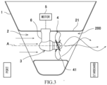
- FIG. 3 is a schematic sectional view of a portion of the hull at which the side thruster equipment according to Comparative Example is located.
- Side thruster equipment 200 according to Comparative Example is configured such that the first slit holes S1, the second slit holes S2, and the return channel 7 are omitted from the side thruster equipment 100 according to the present embodiment.
- the side thruster equipment 200 according to Comparative Example is the same in configuration as the side thruster equipment 100 shown in FIG. 1 .
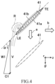
- FIG. 4 is a diagram showing, for example, the water flow with respect to the flat blade 41 of the propeller 4 in the side thruster equipment 200 according to Comparative Example.
- the central axis A of the tunnel 2 i.e., the rotation axis of the propeller 4 corresponds to an origin
- a radial direction from the origin corresponds to an r-axis
- a circumferential direction corresponds to a ⁇ -axis
- a central axis direction of the tunnel 2 corresponds to a z-axis.
- FIG. 4 shows a section of a portion of the flat blade 41 (hereinafter may be simply referred to as a "blade 41") which is located away by a certain distance from a rotation axis center of the propeller 4.
- LE denotes a blade leading edge
- TE denotes a blade trailing edge.
- Broken line arrows show the water flow with respect to the blade 41.
- An arrow a shows a rotational direction of the blade 41
- an arrow b shows a water flow direction in the tunnel 2.
- FIG. 1 shows a vector diagram shown in FIG.
- V denotes a rotational speed of the blade 41
- C1 denotes a water flow speed component in the central axis direction in the tunnel 2
- W1 denotes a relative speed of the water flow to the blade 41
- ⁇ 1 denotes an angle of attack of the water flow with respect to the blade 41.
- a surface of the blade 41 which is located at a front side in the rotational direction serves as a pressure surface 41a, and an opposite surface of the blade 41 serves as a suction surface 41b.
- FIG. 5 is a diagram showing, for example, the water flow with respect to the flat blade 41 of the propeller 4 in the side thruster equipment 100 according to the present embodiment.
- FIG. 5 is drawn in the same manner as FIG. 4 .
- the angle of attack is ⁇ 2 that is smaller than the angle of attack ⁇ 1 in the side thruster equipment 200 according to Comparative Example. This will be described below.
- the flow rate of the water flowing to the blade leading edge LE increases by the water flow which has passed through the return channel 7 and flowed out to the upstream side of the propeller 4. Therefore, a water flow speed component C2 in the central axis direction in the tunnel 2 is larger than the water flow speed component C1 of Comparative Example.
- the angle of attack becomes ⁇ 12 that is smaller than the angle of attack ⁇ 1 of Comparative Example.
- the swirling flow which has flowed into the return channel 7 from the first slit holes S1 passes through the return channel 7 and returns to the upstream side of the propeller 4 through the second slit holes S2.
- a swirling speed of the swirling flow which has returned to the upstream side of the propeller 4 is ⁇ f
- the rotational speed of the blade 41 with respect to the water flow is represented by V - ⁇ f.
- the relative speed of the water flow to the blade 41 becomes W2, and the angle of attack becomes smaller, i.e., becomes ⁇ 2.
- the pressure applied to the propeller 4 increases, and the cavitation is hardly generated.
- the water flow at the downstream side of the propeller 4 returns to the upstream side of the propeller 4, and at this time, the swirling flow generated by the rotation of the propeller 4 returns to the upstream side of the propeller 4, the angle of attack becomes small, i.e., becomes ⁇ 2 especially at a blade tip portion of the blade 41.
- the generation of the leading edge separation at the side of the suction surface 41b of the blade leading edge LE can be suppressed.
- the side thruster equipment 100 since the angle of attack ⁇ 2 is small, the pressure difference between the pressure surface and the suction surface at the blade tip portion of the blade 41 becomes small, and the generation of a blade tip leakage vortex can be suppressed. As above, since the generation of the leading edge separation and the generation of the blade tip leakage vortex can be suppressed, the generation of the cavitation can be suppressed.
- the side thruster equipment 100 according to the present embodiment includes the return channel 7 and the slit holes S1 and S2 as the inlets and outlets of the return channel 7, the generation of the cavitation is suppressed, and a decrease in propulsive force is suppressed. Thus, the energy loss can be reduced.
- controllable pitch propeller is used as the propeller 4.
- a fixed pitch propeller may be used as the propeller 4.
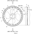
- FIG. 6 is a schematic diagram showing another example of the slit holes that are open on the wall of the tunnel in the present embodiment.
- a left side in FIG. 6 is a sectional view showing the return channel 7 and a portion of the tunnel 2 at which the slit holes are located.
- a right side in FIG. 6 is a side view showing the portion of the tunnel 2 at which the slit holes are located.
- the first slit holes S1 located on a portion of the wall 21 of the tunnel 2 which is closer to the starboard than the propeller 4 in FIG. 1 and the second slit holes S2 located on a portion of the wall 21 of the tunnel 2 which is closer to the port than the propeller 4 in FIG. 1 are the same in shape as each other and are shown as "slit holes Sa" in the example of FIG. 6 .
- the slit holes Sa extend in the circumferential direction of the tunnel 2 and are lined up in a row in the circumferential direction of the tunnel 2.
- the adjacent slit holes Sa are separated from each other by an inter-slit supporting portion 21a that is a portion of the wall 21 which is located between the adjacent slit holes Sa.
- the slit holes Sa are openings located on the wall 21 of the tunnel 2 so as to extend in a direction orthogonal to the extending direction of the tunnel 2.
- the lengths of the slit holes Sa in the circumferential direction of the tunnel 2 are made different from each other such that: the effect of the return channel 7 is preferentially exerted in a region in the tunnel 2 at which the cavitation is easily generated; and the strength of the tunnel 2 is increased by increasing the percentage of the areas of the inter-slit supporting portions 21a in the other portions of the tunnel 2.
- a region in the tunnel 2 in a longitudinal section is divided into an upper region, an intermediate region, and a lower region in this order from an upper side.
- the upper and lower regions in the tunnel 2 are regions where the cavitation is easily generated in the tunnel 2.
- the gear case 6 becomes a hindrance, and the flow speed of the water flowing to the propeller 4 decreases. Therefore, the load increases, and the cavitation is easily generated.
- the upper region is close to the water surface, and therefore, the water pressure is low, the cavitation is easily generated.
- the lower region in the tunnel 2 flow separation easily occurs at a lower portion of an entrance of the tunnel 2, and therefore, the flow speed of the water flowing to the propeller 4 decreases. Therefore, the load increases, and the cavitation is easily generated.
- the lengths of the slit holes Sa in the circumferential direction are set such that the swirling flow which returns to the upstream side of the propeller 4 through the return channel 7 more effectively returns to the upper region and the lower region in the tunnel 2.
- a first predetermined range is set so as to extend in the circumferential direction from a portion of the tunnel 2 which intersects with the direction shown by the arrow e.
- the lengths of the slit holes Sa in the first predetermined range are set to be longer than the lengths of the slit holes Sa located outside the first predetermined range, and thus, the percentage of the areas of the slit holes Sa in the area of the first predetermined range is increased. Therefore, the flow speed of the water flowing to the propeller 4 is increased, and the generation of the cavitation can be further suppressed.
- a second predetermined range is set so as to extend in the circumferential direction from a portion of the tunnel 2 which intersects with a direction intersecting with (for example, orthogonal to) the arrow e.
- the lengths of the slit holes Sa in the second predetermined range are set to be shorter than the lengths of the slit holes Sa located outside the second predetermined range, and thus, the percentage of the areas of the inter-slit supporting portions 21a in the area of the second predetermined range is increased. Therefore, the strength of the tunnel 2 can be secured.
- the lengths of the slit hole Sa may be gradually made different from each other in the circumferential direction of the tunnel 2.
- the first predetermined range is a predetermined range which, when viewed in the central axis direction of the tunnel 2, extends in the circumferential direction of the tunnel 2 from a portion of the tunnel 2 which intersects with a straight line that deviates by a predetermined angle from a vertical line, which passes through the central axis of the tunnel 2 and extends in the vertical direction, in a direction opposite to the rotational direction of the propeller 4.
- the predetermined angle is set in accordance with, for example, the rotational speed of the propeller 4.
- the second predetermined range may be a predetermined range which extends in the circumferential direction of the tunnel 2 and is other than the first predetermined range.
- the propeller 4 is the controllable pitch propeller. Therefore, even when generating the propulsive force in an opposite direction along a left-right direction with respect to the hull, the rotational direction of the propeller 4 stays the same. On the other hand, when using the fixed pitch propeller as the propeller 4 and generating the propulsive force in the opposite direction along the left-right direction with respect to the hull, the rotational direction of the propeller 4 is reversed. As above, when the propeller 4 is the fixed pitch propeller, the rotational direction of the propeller 4 may be reversed.
- the lengths of the slit holes Sa in a predetermined range of an upper portion of the tunnel 2 and a predetermined range of a lower portion of the tunnel 2 may be set longer than the lengths of the slit holes Sa in a range between the predetermined range of the upper portion of the tunnel 2 and the predetermined range of the lower portion of the tunnel 2, and thus, the percentage of the areas of the slit holes Sa may be increased. Even in this case, the lengths of the slit holes Sa may be gradually made different from each other in the circumferential direction of the tunnel 2.
- the lengths of all the slit holes Sa when the lengths of all the slit holes Sa are the same as each other, noises or vibrations of a certain frequency may be generated by the interference between the water flow generated by the rotating blades 41 and the slit holes Sa. Therefore, by making the lengths of the slit holes Sa different from each other, the generation of the noises and vibrations can be suppressed. Even when the lengths of all the slit holes Sa are the same as each other, the noises or vibrations of the above certain frequency may be small, and the strength of the tunnel 2 may be able to be secured by the inter-slit supporting portions 21a. In such a case, the lengths of all the slit holes Sa in the circumferential direction may be set to relatively long and equal lengths.
- Side thruster equipment includes: a cylindrical tunnel extending in a width direction of a hull; a propeller including flat blades and located at a predetermined position in the tunnel such that a rotation axis of the propeller coincides with a central axis of the tunnel; first slit holes located on a portion of a wall of the tunnel, which is closer to starboard than the propeller, so as to be lined up in a circumferential direction of the tunnel, the first slit holes being openings each located so as to extend in a direction intersecting with an extending direction of the tunnel; second slit holes located on a portion of the wall of the tunnel, which is closer to port than the propeller, so as to be lined up in the circumferential direction of the tunnel, the second slit holes being openings each located so as to extend in a direction intersecting with the extending direction of the tunnel; and a return channel that is a tubular channel located such that the tunnel penetrates an inside of the tubular channel, the return
- the water flow at the downstream side of the propeller returns to the upstream side of the propeller through the return channel.
- the first slit holes and the second slit holes as the inlets and outlets of the return channel are open on the wall of the tunnel so as to extend in directions intersecting with the extending direction of the tunnel and are located so as to be lined up in the circumferential direction of the tunnel, the swirling flow generated by the rotation of the propeller returns to the upstream side of the propeller. Therefore, the angle of attack especially at the blade tip portion of the flat blade can be made small, and the generation of the leading edge separation and the generation of the blade tip leakage vortex can be suppressed. Thus, the generation of the cavitation can be suppressed.
- the side thruster equipment includes the return channel and the first slit holes and the second slit holes as the inlets and the outlets, the generation of the cavitation can be suppressed, and a decrease in propulsive force is suppressed. Thus, the energy loss can be reduced.
- the side thruster equipment according to a second aspect of the present disclosure is configured such that in the side thruster equipment according to the first aspect, each first slit hole and each second slit hole are located so as to extend in respective directions that intersect with the circumferential direction of the tunnel in opposite directions.
- the side thruster equipment according to a third aspect of the present disclosure is configured such that: in the side thruster equipment according to the second aspect, when viewed in the extending direction of the tunnel, the first slit holes are located so as to be continuous over an entire periphery of the tunnel; and when viewed in the extending direction of the tunnel, the second slit holes are located so as to be continuous over the entire periphery of the tunnel.
- the swirling flow at the downstream side of the propeller can satisfactorily return to the upstream side of the propeller through the return channel.
- the side thruster equipment according to a fourth aspect of the present disclosure is configured such that in the side thruster equipment according to the first aspect, the first slit holes and the second slit holes are located so as to extend in the circumferential direction of the tunnel.
- the side thruster equipment according to a fifth aspect of the present disclosure is configured such that: in the side thruster equipment according to the fourth aspect, lengths of the first slit holes in the circumferential direction of the tunnel are made different from each other; and lengths of the second slit holes in the circumferential direction of the tunnel are made different from each other.
- noises and vibrations of a certain frequency which are generated by the interference between the water flow and the slit holes when the lengths of all the first slit holes are the same as each other or when the lengths of all the second slit holes are the same as each other can be suppressed.
Landscapes
- Chemical & Material Sciences (AREA)
- Engineering & Computer Science (AREA)
- Combustion & Propulsion (AREA)
- Mechanical Engineering (AREA)
- Ocean & Marine Engineering (AREA)
- Structures Of Non-Positive Displacement Pumps (AREA)
Applications Claiming Priority (2)
| Application Number | Priority Date | Filing Date | Title |
|---|---|---|---|
| JP2022114674A JP7860840B2 (ja) | 2022-07-19 | 2022-07-19 | サイドスラスタ装置 |
| PCT/JP2023/021353 WO2024018777A1 (ja) | 2022-07-19 | 2023-06-08 | サイドスラスタ装置 |
Publications (2)
| Publication Number | Publication Date |
|---|---|
| EP4559802A1 true EP4559802A1 (de) | 2025-05-28 |
| EP4559802A4 EP4559802A4 (de) | 2026-08-05 |
Family
ID=89617454
Family Applications (1)
| Application Number | Title | Priority Date | Filing Date |
|---|---|---|---|
| EP23842709.0A Pending EP4559802A4 (de) | 2022-07-19 | 2023-06-08 | Seitenschubvorrichtung |
Country Status (5)
| Country | Link |
|---|---|
| EP (1) | EP4559802A4 (de) |
| JP (1) | JP7860840B2 (de) |
| KR (1) | KR20250021579A (de) |
| CN (1) | CN118973907A (de) |
| WO (1) | WO2024018777A1 (de) |
Family Cites Families (6)
| Publication number | Priority date | Publication date | Assignee | Title |
|---|---|---|---|---|
| YU36655B (en) * | 1973-12-05 | 1984-08-31 | Orenstein & Koppel Ag | Openings for channels of a jet-type steering device or at water vessel on a floating object |
| DE3300380A1 (de) * | 1983-01-07 | 1984-07-12 | Licentia Patent-Verwaltungs-Gmbh, 6000 Frankfurt | Unterwasserpropellerantrieb |
| JPS59109599U (ja) * | 1983-01-14 | 1984-07-24 | 三井造船株式会社 | サイドスラスタのエア−エミツシヨン装置 |
| JPS6451599U (de) * | 1987-09-28 | 1989-03-30 | ||
| US6164230A (en) | 1999-08-20 | 2000-12-26 | The United States Of America As Represented By The Secretary Of The Navy | Passive system for mitigation of thruster wake deficit |
| DE102013109713B4 (de) * | 2013-09-05 | 2020-10-29 | Jastram Gmbh & Co. Kg | Querstrahlruderanlage und Regelungsverfahren für eine Querstrahlruderanlage |
-
2022
- 2022-07-19 JP JP2022114674A patent/JP7860840B2/ja active Active
-
2023
- 2023-06-08 KR KR1020257001295A patent/KR20250021579A/ko active Pending
- 2023-06-08 EP EP23842709.0A patent/EP4559802A4/de active Pending
- 2023-06-08 CN CN202380030413.1A patent/CN118973907A/zh active Pending
- 2023-06-08 WO PCT/JP2023/021353 patent/WO2024018777A1/ja not_active Ceased
Also Published As
| Publication number | Publication date |
|---|---|
| EP4559802A4 (de) | 2026-08-05 |
| JP2024012890A (ja) | 2024-01-31 |
| WO2024018777A1 (ja) | 2024-01-25 |
| JP7860840B2 (ja) | 2026-05-18 |
| KR20250021579A (ko) | 2025-02-13 |
| CN118973907A (zh) | 2024-11-15 |
Similar Documents
| Publication | Publication Date | Title |
|---|---|---|
| EP4206070A1 (de) | Ruder | |
| KR20130029356A (ko) | 프로펠러 노즐 | |
| EP2500260B1 (de) | Antriebsvorrichtung für schiffe | |
| KR101313183B1 (ko) | 프로펠러 보스 캡 및 이를 구비한 추진장치 | |
| EP4122813B1 (de) | Ruder mit einem ruder und einem ruder eines schiffsruders, die auf beiden seiten des propellers angeordnet sind | |
| KR20070089622A (ko) | 3개의 샤프트 라인을 구비하는 전기 배 추진 시스템 | |
| JP7860840B2 (ja) | サイドスラスタ装置 | |
| CN107539445B (zh) | 船舶用方向舵 | |
| KR20120098941A (ko) | 덕트 부착 스러스터 및 이를 구비한 선박 | |
| CN113815828A (zh) | 一种充气式喷水推进器 | |
| JP5244341B2 (ja) | 船舶用推進装置及び船舶用推進装置の設計方法 | |
| JP2013043629A (ja) | 船舶用推進器 | |
| US6164230A (en) | Passive system for mitigation of thruster wake deficit | |
| EP4059830A2 (de) | Schiffsantrieb, wasserfahrzeug | |
| CN214190056U (zh) | 船用喷射矢量转向装置 | |
| JP2012116329A (ja) | 船舶推進装置 | |
| KR20110036148A (ko) | 선박의 터널 스러스터 | |
| KR101323795B1 (ko) | 선박 | |
| WO1998057848A1 (en) | Contra-rotating ducted impellers | |
| KR20140072824A (ko) | 덕트 장치 | |
| JPS6061397A (ja) | 舶用プロペラ | |
| US7144282B1 (en) | Contoured rudder maneuvering of waterjet propelled sea craft | |
| KR20160149877A (ko) | 선박용 추진 장치 | |
| EP4549309B1 (de) | Verbessertes segelantriebsantriebssystem für boote | |
| CN222833031U (zh) | 一种船舶用侧推结构及船舶 |
Legal Events
| Date | Code | Title | Description |
|---|---|---|---|
| STAA | Information on the status of an ep patent application or granted ep patent |
Free format text: STATUS: THE INTERNATIONAL PUBLICATION HAS BEEN MADE |
|
| PUAI | Public reference made under article 153(3) epc to a published international application that has entered the european phase |
Free format text: ORIGINAL CODE: 0009012 |
|
| STAA | Information on the status of an ep patent application or granted ep patent |
Free format text: STATUS: REQUEST FOR EXAMINATION WAS MADE |
|
| 17P | Request for examination filed |
Effective date: 20250107 |
|
| AK | Designated contracting states |
Kind code of ref document: A1 Designated state(s): AL AT BE BG CH CY CZ DE DK EE ES FI FR GB GR HR HU IE IS IT LI LT LU LV MC ME MK MT NL NO PL PT RO RS SE SI SK SM TR |
|
| DAV | Request for validation of the european patent (deleted) | ||
| DAX | Request for extension of the european patent (deleted) | ||
| A4 | Supplementary search report drawn up and despatched |
Effective date: 20260629 |
|
| RIC1 | Information provided on ipc code assigned before grant |
Ipc: B63H 25/42 20060101AFI20260626BHEP Ipc: B63H 25/46 20060101ALI20260626BHEP |