EP4560075A1 - Selbstbearbeitbare beton- und stahlbrücke ohne schwere wartung - Google Patents
Selbstbearbeitbare beton- und stahlbrücke ohne schwere wartung Download PDFInfo
- Publication number
- EP4560075A1 EP4560075A1 EP24214094.5A EP24214094A EP4560075A1 EP 4560075 A1 EP4560075 A1 EP 4560075A1 EP 24214094 A EP24214094 A EP 24214094A EP 4560075 A1 EP4560075 A1 EP 4560075A1
- Authority
- EP
- European Patent Office
- Prior art keywords
- support
- bridge
- slab
- reinforcing members
- steel
- Prior art date
- Legal status (The legal status is an assumption and is not a legal conclusion. Google has not performed a legal analysis and makes no representation as to the accuracy of the status listed.)
- Pending
Links
Images


Classifications
-
- E—FIXED CONSTRUCTIONS
- E01—CONSTRUCTION OF ROADS, RAILWAYS, OR BRIDGES
- E01D—CONSTRUCTION OF BRIDGES, ELEVATED ROADWAYS OR VIADUCTS; ASSEMBLY OF BRIDGES
- E01D19/00—Structural or constructional details of bridges
- E01D19/12—Grating or flooring for bridges; Fastening railway sleepers or tracks to bridges
- E01D19/125—Grating or flooring for bridges
-
- E—FIXED CONSTRUCTIONS
- E01—CONSTRUCTION OF ROADS, RAILWAYS, OR BRIDGES
- E01D—CONSTRUCTION OF BRIDGES, ELEVATED ROADWAYS OR VIADUCTS; ASSEMBLY OF BRIDGES
- E01D2/00—Bridges characterised by the cross-section of their bearing spanning structure
- E01D2/02—Bridges characterised by the cross-section of their bearing spanning structure of the I-girder type
-
- E—FIXED CONSTRUCTIONS
- E01—CONSTRUCTION OF ROADS, RAILWAYS, OR BRIDGES
- E01D—CONSTRUCTION OF BRIDGES, ELEVATED ROADWAYS OR VIADUCTS; ASSEMBLY OF BRIDGES
- E01D2101/00—Material constitution of bridges
- E01D2101/20—Concrete, stone or stone-like material
- E01D2101/24—Concrete
- E01D2101/26—Concrete reinforced
- E01D2101/268—Composite concrete-metal
Definitions
- the present invention relates to the field of bridges, particularly railway bridges.
- a railway track comprises, in a known manner, two parallel longitudinal rails fixed to a plurality of sleepers arranged perpendicular to the rails.
- the sleepers themselves rest on a rigid support or on ballast supporting the railway track.
- railway bridges In order to ensure the continuity of the railway track over obstacles, such as, for example, gaps, roads, railway tracks or waterways, it is known to have railway bridges at these locations to support the track.
- Such bridges can be made of metal and/or concrete.
- a railway bridge most often comprises, in a known manner, a concrete support slab configured to support a portion of railway track.
- the support slab is configured to receive and support the plurality of sleepers or ballast on which the plurality of sleepers rest.
- the assembly comprising the support slab, the portion of railway track, the plurality of sleepers and/or ballast forms the deck of the railway bridge.
- railway bridges are generally designed with important dimensions, including the thickness of the slab, which determines their capacity to withstand the passage of a vehicle such as a train.
- the height available around the track to design the slab is an essential criterion for choosing the type of bridge to be used.
- the deck of the railway bridge is placed on support devices generally containing rubber or an elastomer so as to support and absorb the forces transmitted by the deck.
- the invention thus aims to eliminate at least some of these drawbacks, in particular to reduce heavy maintenance operations on bridges.
- the invention relates to a bridge comprising a support slab.
- the support slab comprises an upper face arranged to support a traffic lane and a lower face opposite the upper face.
- Said bridge further comprises a plurality of reinforcing members secured at least to the lower face of the slab so as to improve its mechanical strength.
- Said slab is at least partially made of concrete and the plurality of reinforcing members is at least partially made of self-weathering steel.
- Said slab at least partially encases said reinforcing members.
- Self-weathering steel advantageously eliminates the need for painting reinforcement members that are subject to external conditions, thereby reducing maintenance.
- the at least partially concrete support slab at least partially encasing the at least partially self-weathering steel reinforcement members improves the mechanical strength of the bridge.
- the cooperation of concrete and self-weathering steel increases the adhesion between the support slab and the reinforcement member, thereby strengthening the bridge structure.
- the support slab includes a proportion of ultra-high performance fiber-reinforced concrete.
- Ultra-high performance concrete has a high binder content, which results in the absence of capillary porosity in the support slab. Thus, UHPC prevents water infiltration into the support slab and its stagnation. It thus increases the lifespan of the bridge's waterproofing, at least twice as long compared to a conventional bridge.
- Ultra-high performance concrete includes internal reinforcements that advantageously transmit mechanical forces to the reinforcement members, at least partially made of self-weathering steel. This improves the transfer of mechanical forces between the reinforcement members and the internal reinforcements.
- the support slab comprises a slab body and a sealing layer, the sealing layer covering the slab body and being interposed between the latter and said traffic lane, said sealing layer forming the proportion of ultra-high performance fiber-reinforced concrete of the support slab.
- the ultra-high-performance fiber-reinforced concrete waterproofing layer protects the concrete slab body, particularly from water ingress and stagnation. It thus increases the lifespan of the bridge's waterproofing, at least twice as long as that of a conventional bridge.
- the waterproofing layer also eliminates the work required for maintaining and replacing bridge waterproofing, which involves removing the entire track on the bridge, re-sealing it, and reinstalling the track on the bridge.
- the sealing layer has a thickness of between 3cm and 5cm.
- the support slab is made entirely of ultra-high-performance fiber-reinforced concrete.
- the bridge further comprises at least one support member for said bridge, said plurality of reinforcing members being embedded at least partially in said support member.
- said plurality of reinforcing members is entirely embedded in said support member.
- the at least partial embedding of the plurality of reinforcement members in the support member makes it possible to dispense with the need for support devices made at least partially of rubber and therefore with their upkeep and maintenance.
- the replacement of said support devices requires lifting the deck to replace the support device to be changed with a new one, which causes traffic to stop on the bridge.
- each reinforcement member comprises at least two support beams made of self-patinating steel, said support beams each being coated at least in part by the support slab.
- each reinforcement member comprises at least two support beams and a plurality of self-patinating steel attachment systems, the plurality of attachment systems projecting from each support beam, said attachment systems being coated by the support slab.
- the bridge further comprises at least one reinforcing plate extending between the support beams and the lower face of the support slab, the plurality of attachment systems projecting from said reinforcing plate.
- the plurality of attachment systems is made from the material of the reinforcement plate.
- FIG. 1 is a front and sectional view of a bridge according to a first embodiment of the invention, comprising a support slab secured to a plurality of reinforcing members, said plurality of reinforcing members being directly embedded in a support member;
- FIG. 2 is an exploded perspective view of a variant of the bridge of the Figure 1 , in which the plurality of reinforcing members is connected to support devices, themselves connected to the support member;
- FIG. 3 is an exploded perspective view of a variant of the bridge of the Figure 1 , wherein the plurality of reinforcing members are fully embedded in the support member;
- FIG. 4 is a front and sectional view of a bridge according to a second embodiment of the invention, in which the reinforcing member comprises a plurality of support beams partially coated by the support slab, the plurality of reinforcing members being connected to support devices, themselves connected to the support member;
- FIG. 5 is a view similar to that of the Figure 4 , wherein the plurality of support beams are fully encased by the support slab;
- FIG. 6 is an exploded perspective view of the bridge of the Figure 5 ;
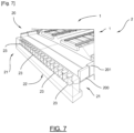
- FIG. 7 is an exploded perspective view of a variant of the bridge of the Figure 4 , wherein the plurality of reinforcing members are fully embedded in the support member.
- the invention relates to a bridge 2, in particular a railway bridge, enabling the support of a traffic lane 1, in particular a railway track, allowing the circulation of vehicles, in particular railway vehicles.
- the invention is not limited to the railway sector but applies to any type of bridge intended to accommodate a traffic lane, road or pedestrian for example.
- the traffic lane 1 comprises two parallel longitudinal rails 3 fixed on a plurality of sleepers 4 arranged perpendicular to the rails 3.
- the sleepers 4 rest on ballast (not shown) which supports and stabilizes the traffic lane 1. Of course, the sleepers 4 can rest directly on the bridge 2, as illustrated in the figures.
- Bridge 2 includes a support slab 20.
- the support slab 20 comprises an upper face and a lower face.
- the upper face is arranged to support a portion of the traffic lane 1 and the lower face is opposite the upper face.
- the support slab 20 may have a length of 15m, a width of 3.5m and a thickness of 15cm.
- the support slab 20 is at least partially made of concrete.
- the support slab 20 may have a proportion of concrete, and in particular a proportion of ultra-high performance fiber-reinforced concrete (UHPC).
- UHPC ultra-high performance fiber-reinforced concrete
- a UHPC has, in a known manner, a resistance ranging from 130 to 250 MPa in compression and from 20 to 50 MPa in flexural tension.
- UHPC has a high binder content which leads to the absence of capillary porosity.
- the support slab 20 may comprise a slab body 200 and a sealing layer 201.
- the sealing layer 201 covers the slab body 200 and is interposed between said slab body 200 and the traffic lane 1.
- the sealing layer 201 is made of ultra-high performance fiber-reinforced concrete and forms the ultra-high performance fiber-reinforced concrete proportion of the support slab 20.
- the sealing layer 201 has a thickness of between 3cm and 5cm.
- Such a thickness makes it possible to ensure good implementation of the sealing layer 201 while limiting the risks of cracking and costs, in particular the costs linked to the manufacture of said sealing layer 201.
- the waterproofing layer 201 made of ultra-high-performance fiber-reinforced concrete protects the slab body 200, for example made of concrete, in particular from water ingress and stagnation.
- the waterproofing layer 201 thus increases the lifespan of the waterproofing of the bridge 2, at least twice as long as that of a conventional bridge.
- the 201 waterproofing layer eliminates the work involved in maintaining and replacing the waterproofing of bridges, namely removing all the track on the bridge, re-sealing it and reinstalling the track on the bridge.
- the support slab 20 may be made entirely of concrete, in particular, ultra-high performance concrete.
- the support slab 20 made of ultra-high-performance fiber-reinforced concrete prevents water infiltration into the support slab 20 and its stagnation.
- the UHPFRC thus increases the lifespan of the waterproofing of bridge 2, at least twice as long compared to a conventional bridge.
- the BFUP 20 support slab eliminates the work involved in maintaining and replacing the waterproofing of bridges, namely removing the entire track on the bridge, redoing the waterproofing and reinstalling the track on the bridge.
- the support slab 20 could be made of a concrete mixture comprising, for example, UHPFRC and ordinary concrete.
- the bridge 2 further comprises a plurality of reinforcing members 21.
- the plurality of reinforcing members 21 is at least partially made of self-patenting steel.
- the plurality of reinforcing members 21 may have a proportion of self-patinating steel, or be entirely made of self-patinating steel.
- the self-patinating steel is for example under the commercial reference CORTEN.
- the self-patinating steel of the plurality of reinforcing members 21 has the advantage of not requiring the application to the reinforcing members 21 of a corrosion protection system, such as paint.
- Self-weathering steel eliminates the need for maintenance of paint or other corrosion protection systems to be applied to the reinforcement components 21.
- each reinforcing member 21 comprises at least two support beams 23.
- Each support beam 23 can be a so-called PRS beam, i.e. a Welded Reconstituted Beam, or a so-called HEB or HEA laminated beam, i.e. an H or I beam with wide flanges, IPN, i.e. an I beam with a normal profile, or a so-called IPE beam, i.e. an I beam with a European profile, for example.
- PRS beam i.e. a Welded Reconstituted Beam
- HEB or HEA laminated beam i.e. an H or I beam with wide flanges
- IPN i.e. an I beam with a normal profile
- IPE beam i.e. an I beam with a European profile
- each support beam 23 comprises a first portion extending between the support on which the bridge 2 rests and the support slab 20, a second portion extending orthogonally to the first portion, between the latter and the support slab 20 and a third portion extending orthogonally to the first portion, between the latter and the support on which the bridge 2 rests.
- the support slab 20 at least partially covers the reinforcing members 21, so as to improve their mechanical resistance.
- the plurality of reinforcing members 21 is secured to the lower face of the support slab 20 so as to improve its mechanical resistance.
- each reinforcing member 21 comprises at least two support beams 23. As illustrated in the Figures 1 and 2 for example, the reinforcing member 21 comprises four support beams 23, juxtaposed to each other, along the width of the support slab 20.
- the reinforcing member 21 comprises a plurality of attachment systems 24. These attachment systems 24 project from the second portion of each support beam 23, towards the support slab 20 and are coated by the latter.
- the 24 hanging systems are made of self-patenting steel.
- the attachment systems 24 are embedded in the support slab 20 at least partially made of concrete.
- the contact between the concrete of the support slab 20 and the self-patinating steel of the attachment systems 24 makes it possible to increase the adhesion between the support slab 20 and the reinforcing member 21 or the reinforcing members 21. Better adhesion makes it possible to further improve the mechanical strength of the slab and to reinforce the structure of the bridge 2.
- the bridge 2 may further comprise at least one reinforcing plate 25.
- This reinforcing plate 25 extends between the support beams 23 and the lower face of the support slab 20.
- the reinforcing plate 25 extends between the second portion of each of the support beams 23 and the lower face of the support slab 20.
- the plurality of attachment systems 24 protrude from the reinforcing plate 25, rather than from the second portion of the support beams 23.
- the reinforcing plate 25 may for example be made of steel, in particular self-patenting steel.
- the hanging systems 24 can be fixed to the reinforcement plate 25 or made of the same material as the reinforcement plate 25.
- the reinforcement plate 25 can be embedded in the support slab 20.
- the reinforcing members 21 constitute a tie rod making it possible to increase the resistance capacity of the structure of the bridge 2, with respect to bending forces.
- the second portion of the support beams 23, the reinforcing plate 25 and/or the attachment systems 24 have a mechanical role of taking up the majority of the tensile forces due to the bending of the support slab 20 and make it possible to better control the fatigue behavior of the structure due to variable stresses on the traffic lane 1 to give it high durability.
- the plurality of reinforcing members 21 is secured to the support slab 20 so as to improve its mechanical resistance.
- each support beam 23 and more particularly the second portion and a part of the first portion of each support beam 23 is coated in the support slab 20.
- Each reinforcing member 21 comprises at least two support beams 23. As illustrated in the Figure 4 , the reinforcing member 21 comprises eighteen support beams 23, juxtaposed to each other, along the width of the support slab 20.
- Each of the support beams 23 is made of self-weathering steel.
- the support beams 23 are partially embedded in the support slab 20 at least partially made of concrete.
- the contact between the concrete of the support slab 20 and the self-patinating steel of the support beams 23 makes it possible to increase the adhesion between the support slab 20 and the reinforcing member 21 or the reinforcing members 21. Better adhesion makes it possible to further improve the mechanical strength of the slab and to reinforce the structure of the bridge 2.
- the plurality of reinforcing members 21 is entirely coated by the support slab 20.
- each support beam 23 is entirely coated in the support slab 20.
- the support beams 23 are also juxtaposed with each other, according to the width of the support slab 20 and are made of self-patenting steel.
- the total embedding of the support beams 23 in the support slab 20 makes it possible to increase the contact surface between the concrete of the support slab 20 and the self-patinating steel of the support beams 23, and therefore makes it possible to further increase the adhesion between the support slab 20 and the reinforcing member 21 or the reinforcing members 21. Better adhesion makes it possible to further improve the mechanical strength of the slab and to reinforce the structure of the bridge 2.
- the reinforcing members 21 of this second embodiment constitute, just like those of the first embodiment, a tie rod making it possible to increase the resistance capacity of the structure of the bridge 2, with respect to bending forces.
- the support beams 23 have a mechanical role of taking up the majority of the tensile forces due to the bending of the support slab 20 and make it possible to better control the fatigue behavior of the structure due to variable stresses on the traffic lane 1 to give it high durability.
- the bridge 2 according to the invention further comprises at least one support member 22 for the bridge 2 on its support.
- the support member 22 is for example made of reinforced concrete.
- the bridge 2 may further comprise support devices 5, interposed between the plurality of reinforcement members 21 and the support member 22.
- the support devices 5 comprise rubber or any other elastomer and make it possible to absorb the forces transmitted by the plurality of reinforcing members 21, towards the support member 22.
- the plurality of reinforcing members 21 is embedded at least partially in the support member 22.
- This variant is the preferred embodiment of the invention.
- the plurality of reinforcing members 21 is partly embedded in the support member 22, or entirely embedded in the support member 22.
- each support beam 23 is embedded at least partially and connected in the support member 22 by plugging.
- each support beam 23 is entirely embedded in the support member 22, only the attachment systems 24 are not coated by said support member 22.
- each support beam 23 is entirely embedded in the support member 22.
- the connection between the support slab 20 and the support beams 23 is effected by means of an anchoring system comprising a plurality of reinforcements, in particular made of steel, which extend from the support slab 20 and in the direction of said support beams 23. Said reinforcements pass through the support beams 23 through holes made in said support beams 23.
- the embedding of the plurality of reinforcement members 21 in the support member 22 makes it possible to dispense with the support devices 5 and therefore with their upkeep and maintenance.
- the replacement of the support devices 5 requires lifting the deck to replace the support device to be changed with a new one, which causes traffic to stop on the bridge 2.
- the bridge 2 according to the invention requires few maintenance operations, in particular concerning the sealing of the support slab 20, the corrosion of the reinforcement members 21 and the use of the support devices 5, while making it possible to improve the mechanical resistance of the support slab 20 and to reinforce the structure of the bridge 2.
Landscapes
- Engineering & Computer Science (AREA)
- Architecture (AREA)
- Civil Engineering (AREA)
- Structural Engineering (AREA)
- Bridges Or Land Bridges (AREA)
Applications Claiming Priority (1)
| Application Number | Priority Date | Filing Date | Title |
|---|---|---|---|
| FR2313118A FR3155840B1 (fr) | 2023-11-27 | 2023-11-27 | Pont en béton et acier auto-patinable sans maintenance lourde |
Publications (1)
| Publication Number | Publication Date |
|---|---|
| EP4560075A1 true EP4560075A1 (de) | 2025-05-28 |
Family
ID=89834005
Family Applications (1)
| Application Number | Title | Priority Date | Filing Date |
|---|---|---|---|
| EP24214094.5A Pending EP4560075A1 (de) | 2023-11-27 | 2024-11-20 | Selbstbearbeitbare beton- und stahlbrücke ohne schwere wartung |
Country Status (2)
| Country | Link |
|---|---|
| EP (1) | EP4560075A1 (de) |
| FR (1) | FR3155840B1 (de) |
Citations (4)
| Publication number | Priority date | Publication date | Assignee | Title |
|---|---|---|---|---|
| US7197854B2 (en) * | 2003-12-01 | 2007-04-03 | D.S. Brown Co. | Prestressed or post-tension composite structural system |
| DE202018105605U1 (de) * | 2018-09-28 | 2018-11-26 | Dominik Steiger | Brückenrandsystem |
| CN111576228A (zh) * | 2020-05-26 | 2020-08-25 | 浙江交通职业技术学院 | 一种更具整体性能的钢-混组合梁桥结构的拼装方法 |
| US20210017722A1 (en) * | 2019-07-18 | 2021-01-21 | Samuel, Son & Co., Limited | Shallow single plate steel tub girder |
-
2023
- 2023-11-27 FR FR2313118A patent/FR3155840B1/fr active Active
-
2024
- 2024-11-20 EP EP24214094.5A patent/EP4560075A1/de active Pending
Patent Citations (4)
| Publication number | Priority date | Publication date | Assignee | Title |
|---|---|---|---|---|
| US7197854B2 (en) * | 2003-12-01 | 2007-04-03 | D.S. Brown Co. | Prestressed or post-tension composite structural system |
| DE202018105605U1 (de) * | 2018-09-28 | 2018-11-26 | Dominik Steiger | Brückenrandsystem |
| US20210017722A1 (en) * | 2019-07-18 | 2021-01-21 | Samuel, Son & Co., Limited | Shallow single plate steel tub girder |
| CN111576228A (zh) * | 2020-05-26 | 2020-08-25 | 浙江交通职业技术学院 | 一种更具整体性能的钢-混组合梁桥结构的拼装方法 |
Also Published As
| Publication number | Publication date |
|---|---|
| FR3155840A1 (fr) | 2025-05-30 |
| FR3155840B1 (fr) | 2025-12-05 |
Similar Documents
| Publication | Publication Date | Title |
|---|---|---|
| EP0323285B1 (de) | Schrägseile und deren Verankerung | |
| FR2689532A1 (fr) | Structure de support de charges. | |
| EP0437143B1 (de) | Verbesserungen an Schrägseilbrücken und insbesondere an deren Seilen, Pfeilern und Fahrbahnen | |
| EP0381547B1 (de) | Verfahren zur Herstellung einer vergrabenen Leitung | |
| FR3155840A1 (fr) | Pont en béton et acier auto-patinable sans maintenance lourde | |
| BE1030535B1 (fr) | Structure de tunnelier a precontrainte a faible rigidite et a haute resistance, ainsi que son procede de construction | |
| EP0287442B1 (de) | Vorgespanntes Stahlrohr, insbesondere für Ankerleinen von vertikal verankerten Bohrplattformen, Verfahren zu dessen Handhabung und Aufstellung sowie Plattform mit solchen Rohren | |
| EP3263766A1 (de) | Betontragplatte für ein schienenfahrzeug und/oder ein fahrzeug mit geführten luftreifen | |
| FR3155841A1 (fr) | Pont en béton sans maintenance lourde | |
| CA1073721A (fr) | Element pour la construction de joints de retrait ou de dilatation et element composite obtenu avec cet element | |
| FR2724953A1 (fr) | Joint routier perfectionne pour ouvrage d'art | |
| JP3407090B2 (ja) | 伸縮ジョイントのシール材 | |
| FR2937350A1 (fr) | Cale de compensation pour assemblage par brochage de poutres en beton arme ou precontraint | |
| EP0061945B1 (de) | Gleitstuhl und dessen Benutzung in einem Eisenbahnweichensystem | |
| EP1457599B1 (de) | Verfahren zur Herstellung eines schienengleichen Bahnübergangs | |
| FR2505806A3 (fr) | Element de guidage glissant pour coulisseaux se deplacant sur des glissieres | |
| FR2717512A1 (fr) | Joint de chaussée à feuilles. | |
| FR2682141A1 (fr) | Procede pour realiser un joint de construction entre deux elements prefabriques d'un ouvrage, joint de construction s'y rapportant et ouvrage comportant un tel joint. | |
| FR2920791A1 (fr) | Dispositif de maintien de l'ecartement de rails de chemin de fer | |
| FR3025813A1 (fr) | Selle de support de rail de voie ferree | |
| FR2459327A1 (fr) | Blochet de voie ferree surbaissee, notamment pour voie ferree sans ballast | |
| BE1014719A3 (fr) | Joint de dilatation en aluminium coule a la resine. | |
| EP2865808A1 (de) | Durchgehende Fahrbahn auf Viaduktbauwerk | |
| EP0952307A1 (de) | Verfahren zur Errichtung einer Struktur unterhalb einer Trägböschung eines Gleises bzw. einer Fahrbahn | |
| EP4673607A1 (de) | Fussgänger-fahrwegstruktur, insbesondere für eine eisenbahnstation |
Legal Events
| Date | Code | Title | Description |
|---|---|---|---|
| PUAI | Public reference made under article 153(3) epc to a published international application that has entered the european phase |
Free format text: ORIGINAL CODE: 0009012 |
|
| STAA | Information on the status of an ep patent application or granted ep patent |
Free format text: STATUS: THE APPLICATION HAS BEEN PUBLISHED |
|
| AK | Designated contracting states |
Kind code of ref document: A1 Designated state(s): AL AT BE BG CH CY CZ DE DK EE ES FI FR GB GR HR HU IE IS IT LI LT LU LV MC ME MK MT NL NO PL PT RO RS SE SI SK SM TR |
|
| STAA | Information on the status of an ep patent application or granted ep patent |
Free format text: STATUS: REQUEST FOR EXAMINATION WAS MADE |
|
| 17P | Request for examination filed |
Effective date: 20251121 |