EP4560076A1 - Barrierenübergangsrahmen - Google Patents
Barrierenübergangsrahmen Download PDFInfo
- Publication number
- EP4560076A1 EP4560076A1 EP23211340.7A EP23211340A EP4560076A1 EP 4560076 A1 EP4560076 A1 EP 4560076A1 EP 23211340 A EP23211340 A EP 23211340A EP 4560076 A1 EP4560076 A1 EP 4560076A1
- Authority
- EP
- European Patent Office
- Prior art keywords
- transition
- thrie
- chord
- panel
- weldment
- Prior art date
- Legal status (The legal status is an assumption and is not a legal conclusion. Google has not performed a legal analysis and makes no representation as to the accuracy of the status listed.)
- Withdrawn
Links
Images





Classifications
-
- E—FIXED CONSTRUCTIONS
- E01—CONSTRUCTION OF ROADS, RAILWAYS, OR BRIDGES
- E01F—ADDITIONAL WORK, SUCH AS EQUIPPING ROADS OR THE CONSTRUCTION OF PLATFORMS, HELICOPTER LANDING STAGES, SIGNS, SNOW FENCES, OR THE LIKE
- E01F15/00—Safety arrangements for slowing, redirecting or stopping errant vehicles, e.g. guard posts or bollards; Arrangements for reducing damage to roadside structures due to vehicular impact
- E01F15/02—Continuous barriers extending along roads or between traffic lanes
- E01F15/04—Continuous barriers extending along roads or between traffic lanes essentially made of longitudinal beams or rigid strips supported above ground at spaced points
- E01F15/0407—Metal rails
-
- E—FIXED CONSTRUCTIONS
- E01—CONSTRUCTION OF ROADS, RAILWAYS, OR BRIDGES
- E01F—ADDITIONAL WORK, SUCH AS EQUIPPING ROADS OR THE CONSTRUCTION OF PLATFORMS, HELICOPTER LANDING STAGES, SIGNS, SNOW FENCES, OR THE LIKE
- E01F15/00—Safety arrangements for slowing, redirecting or stopping errant vehicles, e.g. guard posts or bollards; Arrangements for reducing damage to roadside structures due to vehicular impact
- E01F15/02—Continuous barriers extending along roads or between traffic lanes
- E01F15/08—Continuous barriers extending along roads or between traffic lanes essentially made of walls or wall-like elements ; Cable-linked blocks
- E01F15/081—Continuous barriers extending along roads or between traffic lanes essentially made of walls or wall-like elements ; Cable-linked blocks characterised by the use of a specific material
- E01F15/083—Continuous barriers extending along roads or between traffic lanes essentially made of walls or wall-like elements ; Cable-linked blocks characterised by the use of a specific material using concrete
Definitions
- This disclosure relates to a preassembled traffic barrier system designed for the special application of road to anchor transitions, such as a bridge transition, where the transitions resist deflection in multiple planes.
- Road-side guardrails installed along highways protect motorists from the road-side hazards including non-recoverable slopes and rigid objects.
- the most common type of road-side protection is the American Association of State Highway and Transportation Officials (AASHTO) M 180 W-Beam Guardrail Panel (guardrail).
- AASHTO American Association of State Highway and Transportation Officials
- guardrail W-Beam Guardrail Panel
- Guardrail and other types of road-side safety devices are deemed 'crashworthy' or proven acceptable for use under specified conditions either through physical crash testing via AASHTO Manual of Assessing Safety Hardware (MASH) or in-service performance.
- MASH Manual of Assessing Safety Hardware
- road-side guardrail is to be connected to a rigid object, such as a bridge barrier or bridge pier
- the approach road-side guardrail is gradually stiffened so vehicular pocketing, snagging, or penetration at the point of connection between transition and a rigid object can be avoided.
- Pocketing is an undesirable behavior of guardrail involving relatively large lateral displacements within a relatively short longitudinal distance that can result in large longitudinal decelerations as the front of a vehicle contacts a portion of a barrier deformed at a sharp angle relative to the vehicle's path.
- Penetration is the overall failure and separation of a guardrail, allowing an impacting vehicle to access an area of concern/hazard the guardrail intends to shield.
- Snagging is contact between a portion of a vehicle, such as a wheel or frame element, and the guardrail component that is approximately perpendicular to the normal direction of vehicle travel.
- the most common type of snagging is when a wheel engages the side of a guardrail post. The degree of snagging depends on the degree of engagement.
- Transitions for locations where drainage features e.g., curbs, drainage drop-basins, curb inlets, drainage swales, and public utilities (telecommunications, natural gas) are constructed directly adjacent to the rigid object are susceptible to initiating vehicular instability that can, in some instances, adversely affect the crashworthiness of the transition.
- some transition designs incorporate a curb to reduce the probability of a vehicle snagging on the end of a ridged bridge railing.
- the disclosed barrier transition framework can be used in other locations where transitioning from a flexible barrier system to a solid barrier system. These would include, for example, transitioning from a W-Beam roadside barrier system to a rigid concrete or steel structure.
- the benefits of this application include providing a structure of intermediate flexibility capable of transitioning over drainage and utility features as described above.
- a significant disadvantage of conventional guardrail bridge transitions is that they often conflict with utilities and drain structures.
- a disadvantage of conventional guardrail bridge transitions is that there is an eight-foot gap between the anchoring and post supported guardrail. The guardrail spanning is required to accommodate underground utilities and/or drop basin inlets for off structure drainage, rendering the guardrail spanning this space unreliable.
- Another disadvantage of conventional guardrail bridge transitions is that they are often anchored in poor soil conditions.
- guardrail bridge transitions require an overpour of filler on hillsides leading to bridges. These provide unreliable foundations for anchoring guardrail posts.
- Another disadvantage of conventional guardrail bridge transitions is that drainage at the transition degrades the overpour of filler and poor soil surrounding support posts.
- Another disadvantage of conventional guardrail bridge transitions as they provide a guardrail that is too rigid, or too soft. An example of a guardrail that is too soft is one in which posts are secured in soft soil.
- guardrail bridge transition system that overcomes these disadvantages and provides a safer entry and exit between roads and bridges.
- a guardrail bridge transition assembly that accommodates utilities and drainage structures without interference, is not subject to poor soil foundation for securing guardrail posts and is not subject to excessive erosion by drainage.
- a guardrail bridge transition system that provides a greater resistance to deflection, even though extending over a longer span before attachment to a subterranean post.
- a guardrail bridge transition that minimizes on location assembly and construction requirements.
- An advantage of the embodiments of the disclosed guardrail bridge transition system is that it provides an improved performance that is applicable to both existing transition installations and new transition installations. Another advantage of the embodiments of the disclosed invention is that it comprises a sled component that arrives on-site preassembled and ready for installation. Another advantage of the embodiments of the disclosed invention is that it provides significant time savings on schedule, where post driving operations are reduced by eliminating at least three larger transition posts.
- Another advantage of the present invention is that it can be used to replace in-service transitions, as well as new installations. Another advantage of the present invention is that it is fully reversable for use on either side of the road. Another advantage of the present invention is that it provides a visually seamless integration with a thrie-beam guardrail installed before the transition.
- a primary advantage of the embodiments of the disclosed invention is that it provides a traffic bridge barrier system that uniquely resists deflection in multiple planes, thus providing safer entry and exit transitions between roads and bridges. Another advantage of the embodiments of the disclosed invention is that it provides a bridge transition assembly that accommodates utilities and drainage structures without interference by means of a longer span than conventional transitions. Another advantage of the embodiments of the disclosed invention is that it provides a system that is less vulnerable to failure due to poor soil features proximate to the bridge.
- Another advantage of the embodiments of the disclosed invention is that it provides a foundation for securing guardrail posts that is less vulnerable to excessive erosion by drainage.
- the disclosed invention provides a unique solution to the engineering constraints and challenges of providing a bridge transition that provides increased safety and cost-efficient installation and repair and overcomes the disadvantages of known solutions. Further, the embodiments of the disclosed invention satisfy the crash test requirements of AASHTO MASH Test Level 3, Test 3-20, and Test 3-21.
- a transition framework and transition assembly are disclosed.
- a prefabricated transition framework for use when transitioning from standard road barriers to an anchored road barrier, such as at the foundation of a bridge transition is disclosed.
- the transition framework is a hot-dipped galvanized steel having a pair of 41 ⁇ 2" OD schedule 80 tubular chords. The ends of the tubulars are beveled and welded in solid connection to an approach deflector at one end and an anchorage plate at the other to maintain the tubulars in stiff parallel orientation.
- the transition framework uniquely resists deflection in two planes, the horizontal plane and the vertical plane, thus providing a significantly improved performance over known previous designs.
- By anchoring the ends of the transition chords vertical expansion of the impacted thrie-beam panel is resisted, absorbing more energy in the thrie-beam distortion and providing greater resistance to horizontal displacement.
- the tested and proven uninterrupted span of 105 inches accommodates all utilities at any transition requiring additional room (i.e., drop-basin for off-structure drainage, public utilities, etc.).
- a transition for anchorage to a concrete barrier at a bridge entrance comprising a tubular upper chord having first and second ends.
- a tubular lower chord is provided, also having first and second ends.
- the first end of each of the upper and lower chords is welded to an approach deflector.
- the second end of each of the upper and lower chords is welded to an anchorage plate.
- the approach deflector is connectable to a subterranean mounted guardrail post, and the end anchor is connectable to a bridge anchor.
- the upper chord and lower chord have a 4.5" outside diameter. In another embodiment, the upper chord and lower chord are schedule 80 tubulars. In another embodiment, the center of the upper chord to the center of the lower chord is separated by a distance of 151 ⁇ 4".
- first and second ends of the tubular upper chord and the first and second ends of the tubular lower chord are beveled.
- the approach deflector further comprises a weldment panel welded to the first beveled end of the upper and lower chords, a connection panel disposed at an obtuse angle to the weldment panel, and a plurality of vertically separated fastener holes on the connection panel for fastener connection to an embedded post.
- a deflection panel is disposed at an obtuse angle to the connection panel to prevent snagging of vehicles impacting the approach deflector.
- the anchorage plate further comprises a weldment panel welded to the second beveled end of each of the upper and lower chords, and a connection panel disposed at an obtuse angle to the weldment panel.
- a plurality of vertically separated holes is provided on the connection panel for receiving fasteners for connection to a concrete block at a bridge entrance.
- a bridge transition assembly having a transition framework comprising a tubular upper chord having first and second ends, a tubular lower chord having first and second ends, an approach deflector welded to the first end of the upper and lower chords, and an anchorage plate welded to the second end of the upper and lower chords.
- the approach deflector is affixed to a guardrail post
- the anchorage plate is affixed to a bridge anchor.
- a first thrie-beam guardrail having a first end and an opposite second end is positioned on the road-side of the bridge transition, and over the upper and lower chords.
- the thrie-beam is affixed to the approach deflector and the guardrail post at its first end, and to a thrie-beam terminal connector at its second end.
- the terminal connector is attached to the anchorage plate and bridge anchor at its second end.
- a second thrie-beam guardrail having a first end and an opposite second end.
- the second thrie-beam is positioned on top of the first thrie-beam in a nested configuration.
- the second thrie-beam is affixed to the first thrie-beam, the approach deflector, and the guardrail post at its first end, and to the first thrie-beam at its second end.
- a field-side thrie-beam guardrail is provided.
- FIG. 1 is a front (road-side) perspective view of a transition framework 1, illustrated in accordance with an embodiment of the invention.
- transition framework 1 comprises a tubular upper chord 10 and a lower chord 20.
- a first end 12 of upper chord 10 and a first end 22 of lower chord 20 are welded to a road-side 32 of an approach deflector 30.
- a second end 14 of upper chord 10 and a second end 24 of lower chord 20 are welded to road-side 52 of an anchorage plate 50.
- FIG. 2 is a back (field-side) perspective view of transition framework 1 in accordance with the embodiment of FIG. 1 .
- approach deflector 30 has a field-side 34 opposite to road-side 32.
- Anchorage plate 50 has a field-side 54 opposite to road-side 52.
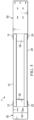
- FIG. 3 is a front side view of transition framework 1 in accordance with the embodiment of FIGS. 1-2 .
- Anchorage plate 50 has a plurality of fastener holes 60.
- Fastener holes 60 receive fasteners 62 for connection of anchorage plate 50 to a concrete bridge anchor 100.
- Approach deflector 30 has a plurality of fastener holes 40.
- Fastener holes 40 receive fasteners 62 for connection of approach deflector 30 to a guardrail post 110.
- FIG. 4 is a top view of transition framework 1 in accordance with the embodiment of FIGS. 1-3 .
- FIG. 5 is a back side view of transition framework 1 in accordance with the embodiment of FIGS. 1-4 .
- upper chord 10 has a first beveled end 12 and a second beveled end 14.
- Lower chord 20 has a first beveled end 22 and a second beveled end 24.
- approach deflector 30 comprises a weldment panel 36 to which are welded the first beveled ends 12 and 22 of tubular upper chord 10 and lower chord 20.
- Anchorage plate 50 comprises a connection panel 58 and a weldment panel 56 to which are welded the second beveled ends 14 and 24 of tubular upper chord 10 and lower chord 20.
- connection panel 38 is disposed at an obtuse angle to weldment panel 36. As best seen in FIG. 5 , fastener holes 40 are disposed on connection panel 38. Referring back to FIG. 4 , a deflector panel 42 is disposed at an obtuse angle to connection panel 38. As best seen in FIG. 11 , deflector panel 42 serves to discourage an impacting vehicle from snagging on guardrail post 110.
- upper chord 10 and lower chord 20 have an outside diameter of approximately 4.5". In another embodiment, upper chord 10 and lower chord 20 are made from schedule 80 tubulars.
- FIG. 6 is an end view of transition framework 1, illustrated as incorporated in bridge transition assembly 5.
- a first thrie-beam 70 is positioned on the road-side of transition framework 1, and over upper chord 10 and lower chord 20 so as to nest first thrie-beam 70 over upper chord 10 and lower chord 20.
- a field-side thrie-beam 80 is positioned on the field-side of transition framework 1, and over upper chord 10 and lower chord 20 so as to nest field-side thrie-beam 80 over upper chord 10 and lower chord 20.
- Fasteners 90 connect first road-side thrie-beam 70 to field-side thrie-beam 80 between upper chord 10 and lower chord 20.
- a second road-side thrie-beam 74 is nested over first road-side thrie-beam 70 to provide additional strength and resistance to deformation.
- thrie-beams 70 and 74 have an accordion-like profile that is presented road-side for impact by a vehicle.
- the center of thrie-beams 70 and 74 would normally expand thrie-beams 70 and 74 vertically in response to a direct impact.
- transition framework 1 resists vertical expansion of thrie-beams 70 and 74, and coincident horizontal deformation.
- the impact of the disclosed invention requires horizontal buckling at the center of thrie-beams 70 and 74 between upper chord 10 and lower chord 20, which absorbs much more energy than horizontal expansion if upper chord 10 and lower chord 20 were not solidly anchored at their ends.
- the benefits increase resistance to deflection and increased probability of a repairable bridge transition on lower to medium vehicle impacts.
- FIG. 7 is a front side sectional view of a thrie-beam terminal connector 72 incorporated in the disclosed embodiments of bridge transition assembly 5. As illustrated in FIG. 7 and as best seen in FIG. 8 , terminal connector 72 is connected to anchorage plate 50 of transition framework 1 and concrete anchor 100 at the entrance to a bridge. Fasteners 62 are located in receiving holes on terminal connector 72 and pass through fastener holes 60 on connection panel 58 of anchorage plate 50 (see FIG. 3 ).
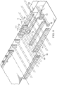
- FIG. 8 is an isometric exploded view of bridge transition assembly 5.
- transition framework 1 is positioned as the transition between guardrail post 110 and concrete anchor 100.
- a spacer 112 may be positioned between guardrail post 110 and transition framework 1.
- a spacer 112 may be positioned between a guardrail post 111 and road-side thrie-beam 70.
- Fasteners 90 connect transition framework 1 and road-side thrie-beams 70 and 74 to guardrail post 111.
- Guardrail post 110 is the first connecting guardrail post on the approach side of concrete anchor 100.
- Guardrail post 111 is the second connecting guardrail post on the approach side of the concrete barrier.
- fasteners 62 rigidly connect anchorage plate 50 of transition framework 1 and terminal connector 72 to concrete anchor 100 at the entrance to a bridge.
- First road-side thrie-beam 70 is positioned over upper chord 10 and lower chord 20.
- Second road-side thrie-beam 74 is nested over first road-side thrie-beam 70 to provide additional strength and resistance to deformation.
- Field-side thrie-beam 80 is positioned on the field-side of transition framework 1, and over upper chord 10 and lower chord 20 so as to nest field-side thrie-beam 80 over upper chord 10 and lower chord 20.
- Fasteners 90 connect first road-side thrie-beam 70 to field-side thrie-beam 80 between upper chord 10 and lower chord 20 to form an envelope over upper chord 10 and lower chord 20.
- First road-side thrie-beam 70 and second road-side thrie-beam 74 are connected to terminal connector 72 by threaded fasteners 62.
- the opposite ends of first road-side thrie-beam 70 and second road-side thrie-beam 74 are connected by threaded fasteners 90 to approach deflector 30 and guardrail post 110.
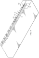
- FIG. 9 is an isometric view of the assembled components of FIG. 8 , illustrating bridge transition assembly 5 assembled with transition framework 1 extending between guardrail post 110 and concrete anchor 100 at a bridge entrance. In this manner, construction of bridge transition assembly 5 is complete.
- transition framework 1 does not require field-side thrie-beam 80 to support rigidly anchored upper chord 10 and lower chord 20, facilitating the very advantageous premanufacture of transition framework 1 for use at the bridge location.
- Transition framework 1 as preassembled, can advantageously be used to replace in-service transitions, as well as new installations. Additionally, transition framework 1 is fully reversable for use on either side of the road. Transition framework 1 provides further significant installation time savings in that it eliminates up to four guardrail posts for post pounding operations.
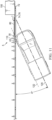
- FIG. 10 is a top view of a MASH Test 3-20 vehicle crash test which was performed in which the disclosed transition framework 1 was incorporated into bridge transition assembly 5 as the bridge transition tested in accordance with MASH testing protocols.
- the vehicle has a centerline of travel 120, and a line of critical impact point, or CIP 122. To satisfy the test requirements, vehicle centerline 120 is at an angle of 25° to bridge transition assembly 5.
- FIG. 11 is a top view of a MASH Test 3-21 with a test vehicle that was performed with the disclosed transition framework 1 incorporated into bridge transition assembly 5, tested in accordance with MASH testing protocols.
- the vehicle has a centerline of travel 120, and a line of critical impact point, or CIP 122. To satisfy the test requirements, vehicle centerline 120 is at an angle of 25° to bridge transition assembly 5.
- deflector panel 42 serves to discourage an impacting vehicle from snagging on guardrail post 110.
- transition framework 1 as incorporated in bridge transition assembly 5 provides a safe bridge transition for vehicles of very different sizes that passes all criteria of MASH Test 3-20 and MASH Test 3-21 requirements and provides the several advantages described herein.
- transition framework 1 and transition assembly 5 are not limited to the application of bridge entrance and egress, but can be used where other solidly anchored road barrier elements need to be transitioned to less resistive barrier elements.
Landscapes
- Engineering & Computer Science (AREA)
- Architecture (AREA)
- Civil Engineering (AREA)
- Structural Engineering (AREA)
- Bridges Or Land Bridges (AREA)
Priority Applications (1)
| Application Number | Priority Date | Filing Date | Title |
|---|---|---|---|
| EP23211340.7A EP4560076A1 (de) | 2023-11-22 | 2023-11-22 | Barrierenübergangsrahmen |
Applications Claiming Priority (1)
| Application Number | Priority Date | Filing Date | Title |
|---|---|---|---|
| EP23211340.7A EP4560076A1 (de) | 2023-11-22 | 2023-11-22 | Barrierenübergangsrahmen |
Publications (1)
| Publication Number | Publication Date |
|---|---|
| EP4560076A1 true EP4560076A1 (de) | 2025-05-28 |
Family
ID=88923716
Family Applications (1)
| Application Number | Title | Priority Date | Filing Date |
|---|---|---|---|
| EP23211340.7A Withdrawn EP4560076A1 (de) | 2023-11-22 | 2023-11-22 | Barrierenübergangsrahmen |
Country Status (1)
| Country | Link |
|---|---|
| EP (1) | EP4560076A1 (de) |
Citations (4)
| Publication number | Priority date | Publication date | Assignee | Title |
|---|---|---|---|---|
| US20040262588A1 (en) * | 2003-06-27 | 2004-12-30 | Trn Business Trust | Variable width crash cushions and end terminals |
| CN210917144U (zh) * | 2019-10-21 | 2020-07-03 | 中交瑞安(北京)交通技术有限公司 | 一种路侧护栏过渡段连接单元 |
| CN116575325A (zh) * | 2023-04-26 | 2023-08-11 | 张家港市诚翔交通科技有限公司 | 一种桥梁过渡护栏 |
| CA3184560A1 (en) * | 2022-05-19 | 2023-11-19 | Vandorf Bt1, Inc. | Barrier transition framework |
-
2023
- 2023-11-22 EP EP23211340.7A patent/EP4560076A1/de not_active Withdrawn
Patent Citations (4)
| Publication number | Priority date | Publication date | Assignee | Title |
|---|---|---|---|---|
| US20040262588A1 (en) * | 2003-06-27 | 2004-12-30 | Trn Business Trust | Variable width crash cushions and end terminals |
| CN210917144U (zh) * | 2019-10-21 | 2020-07-03 | 中交瑞安(北京)交通技术有限公司 | 一种路侧护栏过渡段连接单元 |
| CA3184560A1 (en) * | 2022-05-19 | 2023-11-19 | Vandorf Bt1, Inc. | Barrier transition framework |
| CN116575325A (zh) * | 2023-04-26 | 2023-08-11 | 张家港市诚翔交通科技有限公司 | 一种桥梁过渡护栏 |
Similar Documents
| Publication | Publication Date | Title |
|---|---|---|
| US6854716B2 (en) | Crash cushions and other energy absorbing devices | |
| US4655434A (en) | Energy absorbing guardrail terminal | |
| EP4121603B1 (de) | Verkehrsschranke und schallwandsystem | |
| US8500103B2 (en) | Yielding post guardrail safety system incorporating thrie beam guardrail elements | |
| US20040262588A1 (en) | Variable width crash cushions and end terminals | |
| NZ502793A (en) | Guardrail end terminal for side or front impact with reactor plate at three to four inches above ground level to receive floor structure of vehicle during impact | |
| US7913981B2 (en) | Cable release lever | |
| US11891765B2 (en) | Barrier transition framework | |
| EP3497288B1 (de) | Übergangsbarriere zum verbinden einer permanenten barriere mit einer temporären barriere | |
| EP4560076A1 (de) | Barrierenübergangsrahmen | |
| US20060072967A1 (en) | Transition structure | |
| AU2023233067A1 (en) | Barrier transition framework | |
| BR102023025755A2 (pt) | Armação de transição para conexão a uma âncora de concreto, e, conjunto de transição | |
| EP1861548B1 (de) | Schlagfeste säule | |
| BR102023025755B1 (pt) | Armação de transição para conexão a uma âncora de concreto, e, conjunto de transição | |
| CN223974519U (zh) | 一种防阻块和护栏单元 | |
| US11306453B2 (en) | One-piece metal plate foundation with integral offset plate for guardrails and other structures and guardrail system utilizing same | |
| CA3175588C (en) | Traffic barrier with inertial crash panels and sound barrier | |
| EP2032765B1 (de) | Fahrzeugsicherheitsbarrieren | |
| WO2007144142A1 (en) | Rail for vehicle safety barriers | |
| DESIGNS | Use of Guardrails on Low Fill Bridge Length Culverts | |
| SK72009U1 (sk) | Jednostranné zvodidlo, obzvlášť na krajnice rýchlostných komunikácií |
Legal Events
| Date | Code | Title | Description |
|---|---|---|---|
| PUAI | Public reference made under article 153(3) epc to a published international application that has entered the european phase |
Free format text: ORIGINAL CODE: 0009012 |
|
| STAA | Information on the status of an ep patent application or granted ep patent |
Free format text: STATUS: THE APPLICATION HAS BEEN PUBLISHED |
|
| AK | Designated contracting states |
Kind code of ref document: A1 Designated state(s): AL AT BE BG CH CY CZ DE DK EE ES FI FR GB GR HR HU IE IS IT LI LT LU LV MC ME MK MT NL NO PL PT RO RS SE SI SK SM TR |
|
| STAA | Information on the status of an ep patent application or granted ep patent |
Free format text: STATUS: THE APPLICATION IS DEEMED TO BE WITHDRAWN |
|
| 18D | Application deemed to be withdrawn |
Effective date: 20251129 |