EP4560106A1 - Dispositif de fixation pour un coffre de volet roulant, coffre de volet roulant et fenêtre/porte dotée d'un coffre de volet roulant - Google Patents
Dispositif de fixation pour un coffre de volet roulant, coffre de volet roulant et fenêtre/porte dotée d'un coffre de volet roulant Download PDFInfo
- Publication number
- EP4560106A1 EP4560106A1 EP24214667.8A EP24214667A EP4560106A1 EP 4560106 A1 EP4560106 A1 EP 4560106A1 EP 24214667 A EP24214667 A EP 24214667A EP 4560106 A1 EP4560106 A1 EP 4560106A1
- Authority
- EP
- European Patent Office
- Prior art keywords
- profile
- roller shutter
- fastening
- shutter box
- base element
- Prior art date
- Legal status (The legal status is an assumption and is not a legal conclusion. Google has not performed a legal analysis and makes no representation as to the accuracy of the status listed.)
- Pending
Links
Images


Classifications
-
- E—FIXED CONSTRUCTIONS
- E06—DOORS, WINDOWS, SHUTTERS, OR ROLLER BLINDS IN GENERAL; LADDERS
- E06B—FIXED OR MOVABLE CLOSURES FOR OPENINGS IN BUILDINGS, VEHICLES, FENCES OR LIKE ENCLOSURES IN GENERAL, e.g. DOORS, WINDOWS, BLINDS, GATES
- E06B9/00—Screening or protective devices for wall or similar openings, with or without operating or securing mechanisms; Closures of similar construction
- E06B9/02—Shutters, movable grilles, or other safety closing devices, e.g. against burglary
- E06B9/08—Roll-type closures
- E06B9/11—Roller shutters
- E06B9/17—Parts or details of roller shutters, e.g. suspension devices, shutter boxes, wicket doors, ventilation openings
- E06B9/17007—Shutter boxes; Details or component parts thereof
- E06B9/1703—Fixing of the box; External plastering of the box
Definitions
- the invention relates to a fastening device for fastening a top-mounted roller shutter box having at least one static console in its interior to an upper frame profile of a window or a door, comprising an adapter profile which can be fastened to an upper frame profile of a window or a door and to which a lower base element of a top-mounted roller shutter box can be fastened by locking.
- the invention further relates to a top-mounted roller shutter box comprising a ceiling element, a floor element, an outer wall element, an inner wall element and two opposing side wall elements on which the winding shaft of a roller shutter curtain is mounted, wherein a base element is fastened to the floor element, by means of which the top-mounted roller shutter box can be fastened to an adapter profile and at least one static console is arranged inside, which extends from the base element around the roller shutter curtain to the ceiling element.
- the invention also relates to a window or a door with a top-mounted roller shutter box which is fastened to the upper frame profile of the window or door and to a method for mounting a top-mounted roller shutter box having at least one static bracket in its interior to the upper frame profile of a window or door, wherein an adapter profile is fastened to the upper frame and the top-mounted roller shutter box is fastened with its base element to the adapter profile in a snap-in manner.
- the floor element which is connected to a base element, is attached by means of the base element to an upper horizontally running frame profile of a window or door, which is formed from a hollow plastic profile, wherein the frame profile has a reinforcing profile, preferably made of metal, in at least one of its hollow chambers and wherein the fastening device comprises at least one adapter profile to be firmly attached to the frame profile.
- the adapter profile has fastening elements on its underside, by means of which it can be fastened to an upper frame profile on the top side.
- fastening elements can be, for example, locking elements, preferably fastening elements that run parallel to one another at a distance in the direction of extension and can engage in corresponding locking grooves on the top side of a frame profile.
- An adapter profile can preferably also be screwed, e.g., by screws that engage in the frame profile, preferably in its reinforcement profile.
- Adapter profiles intended for connection to a frame profile that is not a hollow plastic profile can also be flat on the underside, i.e., on the side facing the frame profile, and can be secured only by screwing. This is the case, for example, if the frame profile is a wooden profile.
- the direction of extension for all profiles mentioned in this description of the invention is the direction in which the profiles run with a constant profile cross-section; in particular, for plastic profiles, it is the extrusion direction during the production of the profiles. All other directions refer to the usual installation position of a window or door. Preferably, the directions mentioned in this description of the invention Characteristics of profiles or extended elements are described with regard to their properties when considering the respective profiles/elements in cross-section perpendicular to their extension.
- a lower wall element of a roller shutter box is constructed in two parts and comprises a base element which is or is connected to the adapter profile in a locking manner and a floor element which is or is at least connectable to the base element.
- connection is achieved by sliding the roller shutter box horizontally, particularly toward the outside, after placing it on the adapter profile attached to the upper frame profile, causing the locking elements of the adapter profile and the base element to engage.
- the floor element preferably has a detachable connection to the base element and/or the interior wall element.
- the floor element can be used as a lower inspection hatch
- the interior wall element can be used as an inspection hatch facing the interior of the room.
- plastic hollow profiles as wall elements for the production of top-mounted roller shutter boxes offers many advantages such as good thermal insulation, high air tightness, easy processing and quick installation at the installation site.
- roller shutter box is known that is made of hollow plastic profiles. Such a roller shutter box is easy to install. It is made airtight by interlocking profiles and can be insulated with additional thermal insulation elements to prevent cold bridges in the area of the roller shutter box. Furthermore, a wide range of options can be provided by appropriate profile designs. to create inspection hatches on the underside or on the side facing the inside of the building.
- thermal insulation elements can also preferably be provided in the usual way.
- EP 1 775 415 A2 A special connecting profile is known that can be snapped onto the ceiling element of the roller shutter box.
- the floor element is connected to the window frame, so that the static connection between the upper section of the frame and the ceiling is made via the roller shutter box.
- the rigidity of the side wall elements attached to the front is sufficient to transfer wind loads to the ceiling, for example.
- the frame must be reinforced.
- Reinforcing the PVC frame profile of a window or door is usually achieved by inserting metal reinforcement profiles, especially steel.
- the internal reinforcement is no longer sufficient to prevent significant deformation of the frame under wind loads.
- due to the material properties of the commonly used PVC plastic larger forces acting on the frame cannot be transferred to the building ceiling via the roller shutter box.
- brackets are known for this purpose; one end, particularly the lower end, is connected directly or indirectly to the top of the frame, and the other end, particularly the upper end, is attached to the building ceiling.
- the bracket-shaped area between the ends serves to support the wound-up To encompass the roller shutter curtain and to redirect the wind and suction loads to be diverted and direct them into the ceiling.
- a top-mounted roller shutter box according to the invention comprises at least one such static bracket and the fastening device according to the invention is intended for use with such top-mounted roller shutter boxes.
- the structural bracket is a stiffening element and is mounted inside the roller shutter box where structural requirements exist. It is designed to extend structurally continuously from the window frame to the lintel or ceiling above the roller shutter box.
- the structural bracket is already pre-assembled in the top-mounted roller shutter box and, when the top-mounted roller shutter box is attached to the window or door (snapped into place by sliding the roller shutter box horizontally in accordance with the state of the art), is connected to the window or door frame profile, preferably also to the structural element of the window/door (steel reinforcement), e.g., by means of a screw connection in the state of the art.
- a structural bracket is secured, particularly screwed, from the inside of the roller shutter box after it has been snapped into place.
- the inspection panel particularly the lower floor element or the interior wall element of the roller shutter box facing the interior of the room, must be removed and screwed in place.
- the disadvantage of the additional structural brackets is that they are difficult to install. This is less true for the ceiling mountings, which are usually offset from the plane of the frame closer to the interior of the building, making the mounting points easily accessible when the interior wall element and floor element are removed. This applies even more to the connection to the frame, and possibly also to the metal reinforcement profile within it, because all the screw connections require working within the narrow roller shutter box.
- the installation of conventional structural brackets therefore requires a high number of work steps and increased installation effort.
- the object of the present invention is therefore to provide a fastening device for a top-mounted roller shutter box with at least one internal static bracket, a top-mounted roller shutter box with at least one internal static bracket, a window or a door with such a top-mounted roller shutter box and a method for mounting such a top-mounted roller shutter box, which enables tool-free and thus faster and easier mounting and dismounting.
- the goal should be to ensure that, in the best case scenario, an installer no longer needs to open a roller shutter box after installing the window or door, including the roller shutter box, to perform further work such as screwing the structural bracket, etc.
- the screwing of the structural bracket to a mounting bracket should ideally be eliminated.
- Particularly preferred is a roller shutter box that is connected to the ceiling from the outside and does not need to be opened again after installation.
- the object is achieved in a fastening device of the type mentioned above in that at least one additional reinforcement profile, preferably a metallic additional reinforcement profile, is arranged on the adapter profile, in particular in a top-side recess of the adapter profile.
- the at least one additional reinforcement profile has at least one fastening pin extending upwards from the additional reinforcement profile, the free end of which has a thickened portion.
- the thickened portion is thus preferably a component of the fastening pin at its free end, in particular thus formed integrally with the fastening pin.
- the object is achieved in that the at least one static bracket has a fastening tab resting on the base element, wherein the fastening tab has a fastening opening which is arranged in overlap with a through-opening in the base element.
- a fastening pin of an aforementioned fastening device can be pushed with its thickened portion through the push-through opening and the fastening opening and that the surface of the fastening tab facing away from the base element can be pushed under the thickened portion at least in part.
- the object is accordingly further achieved by a window or a door of the type mentioned at the outset, in which the top-mounted roller shutter box is designed according to the aforementioned solution and is fastened to the frame profile by means of an aforementioned fastening device, wherein the base element is latched to the adapter profile and the at least one fastening pin with its thickened portion is pushed through the through-opening in the base element and the fastening opening in the fastening tab of the at least one static bracket and the surface of the fastening tab facing away from the base element is pushed at least partially under the thickening of the at least one fastening pin.
- the object is achieved in that a preferably metallic additional reinforcement profile is placed on the adapter profile, in particular at least one additional reinforcement profile is inserted into a top-side recess of the adapter profile, which has at least one fastening pin extending upwards from the additional reinforcement profile and having a thickening at its free end, wherein the top-mounted roller shutter box is placed in the direction of gravity onto the at least one fastening pin, wherein the thickening has a through-opening in the base element and a fastening opening in the tab of the at least one static bracket penetrates, and the top-mounted roller shutter box is moved and thereby the base element locks onto the adapter profile, and during the displacement the surface of the fastening tab facing away from the base element is pushed at least partially under the thickening of the at least one fastening pin.
- the invention thus ensures that the at least one structural bracket inside the roller shutter box establishes a connection to the frame profile simply by moving the roller shutter box, because the fastening tab of the structural bracket slides partially under the thickened portion of the fastening pin and is thereby fixed in the direction of the pin extension, in particular in the vertical direction. Since the fastening pin is connected to the adapter profile and the frame profile, in particular also to a reinforcement profile, via the additional reinforcement profile, this results in a preferably positive and/or force-locking connection between the at least one structural bracket and the frame profile.
- the additional reinforcement profile placed on the adapter profile, preferably inserted therein, is preferably also connected, e.g. by means of screws, to the frame profile and/or the metallic reinforcement profile inserted therein.
- the invention can provide that a single, preferably metallic, additional reinforcement profile is inserted into an adapter profile that is continuous across the window width/door width, which carries a number of fastening pins that corresponds to the number of static consoles inside the roller shutter box.
- the invention can also provide for the use of a number of additional reinforcement elements, each with a fastening pin, which corresponds to the number of static brackets inside the roller shutter box.
- the positions of the fastening pins on the additional reinforcement profile(s) correspond to the positions of the fastening openings in the fastening tabs of the static brackets.
- the invention preferably provides that the at least one fastening pin is arranged directly on the additional reinforcement profile or on a mounting plate that is attached to the additional reinforcement profile, e.g., by screwing or welding.
- the design with the mounting plate has the advantage that the additional reinforcement profile can be manufactured and then the at least one fastening pin is attached to the at least one required position using a mounting plate that supports it.
- the at least one additional reinforcement profile preferably the recess in the adapter profile with the at least one additional reinforcement profile embedded therein, is covered by the base element of the top-mounted roller shutter box after its installation.
- the thickening of the free end is tapered in a direction away from the additional reinforcement profile. This facilitates the placement of the roller shutter box on the pin.
- the taper can preferably be formed in that the thickening is at least partially frustoconical or mushroom-head-shaped.
- the thickening is circular, preferably over the entire axial extension of the pin at its free end where the thickening is present, preferably wherein the circular cross-section of the thickening decreases towards the tip of the free end to achieve the taper.
- the thickening of the free end has a flat lower surface opposite the surface of the additional reinforcement profile and/or the mounting plate.
- This flat lower surface preferably lies in a plane that is oriented perpendicular to the direction of extension of the fastening pin.
- the thickening thus lies entirely on the side of the aforementioned plane facing the free end; preferably, the thickening starts in this plane with its flat lower surface and extends from there in a tapered manner towards the tip of the free end.
- the fastening tab which is preferably also flat, can be enclosed between the flat lower surface of the thickening and the preferably flat surface of the base element, in particular in a form-fitting manner, preferably such that no movement of the fastening tab in the axial direction of extension of the fastening pin, in particular in the vertical direction, is possible.
- the fastening opening has a first partial opening region and a second partial opening region which opens into the first partial opening region, preferably wherein the second partial opening region is different in shape from the first partial opening region, in particular has a smaller opening cross-section than the first partial opening region.
- the second partial opening area preferably opens into the first partial opening area in a direction that corresponds to the direction of displacement in which the roller shutter box must be moved in order to achieve the locking between the base element and the adapter profile.
- the opening cross-section of the second partial opening area (at least viewed perpendicular to the displacement direction) is smaller than the The maximum cross-section of the thickening, but larger, particularly in a width perpendicular to a displacement direction to effect locking, than the cross-section of the shaft of the fastening pin below the thickening.
- the first partial opening area is preferably circular, and the second partial opening area is designed as an elongated hole extending in the aforementioned displacement direction.
- the fastening opening preferably has a keyhole-like shape.
- the thickened portion is also circular in cross-section perpendicular to the shaft axis/center axis of the fastening pin, with a maximum diameter that is smaller than the first partial opening area and in particular larger than the second partial opening area.
- a preferred embodiment further provides that the fastening tab of the static console has a stop edge pointing towards the inner wall element and running parallel thereto, which contacting edge rests against a stop of the base element running parallel to the inner wall element.
- the stop is preferably a projection on the surface of the base element facing into the interior of the roller shutter box, which projection runs in the direction of the extension direction of the base element, in particular which corresponds to the extrusion direction of the base element.
- the fastening tab has an edge running perpendicular to the stop edge, wherein these two edges merge into one another with a connecting area, in particular a circular arc-shaped connecting area, in particular the distance of which to the central axis of the fastening pin in the locked state of the roller shutter box is smaller than the distance between the fastening pin central axis and the stop edge.
- the invention allows a structural bracket to be subsequently removed from a roller shutter box, e.g., when access to the roller shutter curtain is required.
- the structural bracket is rotated around the mounting pin, possibly after first being removed from the ceiling element.
- the structural bracket can then be moved to release it from the thickened portion of the mounting pin.
- the fastening pin which has a thickened portion at its free upper end, so that it automatically locks the structural bracket after the roller shutter box has been snapped onto the window or door.
- the structural bracket has a tapered fastening opening that matches the fastening pin. This locking mechanism eliminates the need for additional securing and the resulting opening of the inspection panel of the roller shutter box.
- this innovation optimizes the installation of a top-mounted roller shutter box and increases installation speed.
- the structural support bracket can also be removed without tools. To do this, after opening the inspection panel and removing the insulation, the structural support bracket is removed by pivoting it out sideways.
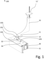
- FIG. 1 For reasons of clarity, only the upper frame profile 30 and the static bracket 10 as well as the fastening device 100 according to the invention consisting of the adapter profile 32 with the additional reinforcement profile 34 and the fastening pin 102 arranged on a mounting plate 101 with the thickening 103 at the upper free end of the fastening pin 102 are shown.
- the fastening device 100 enables the connection of the static console 10 with the frame profile 30, and in particular with the additional metallic reinforcement profile 34 and preferably also with the Reinforcement profile 31 inserted into the frame profile 30, which is arranged within a hollow chamber of the frame profile 30, in particular if the additional reinforcement profile 34 is connected to the reinforcement profile 31 by means of screws.
- connection with the additional reinforcement profile 34 is mandatory, while the connection with the reinforcement profile 31 can be supplementary.
- an additional reinforcement profile 34 is placed on the adapter profile 32, in particular inserted into a top-side recess 32a of the adapter profile 32.
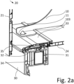
- the recess 32a is formed between the environmental-side receptacle 32b and the room-side, in particular locking-acting receptacle 32c of the adapter profile 32, as Figure 1a better shown in detail.
- the additional reinforcement profile 34 has a large width in cross-section and thus a high area moment of inertia, which is effective against forces acting transversely to the frame profile 30, such as wind loads in particular.
- the adapter profile 32 represents a stepped profile, viewed perpendicular to the direction of extension, with a lower step surface that lies in the recess 32a and an upper step surface, in particular at least substantially parallel to the lower step surface, which rests on the room-side receptacle 32c. It is preferably provided that a base element 33 is inserted into the environment-side receptacle 32b, in particular in a non-locking manner, and is inserted into the room-side receptacle, in particular in a locking manner. The situation is described in detail in the Figure 2A shown.
- the securing device 100 represents an easy-to-install and highly resilient connection as follows:
- the mounting plate 101 is fastened to the additional reinforcement profile 34 located in the adapter profile 32 using the fastening pin 102, e.g., firmly mounted using fastening screws 105.
- Figure 1 also represents the static bracket 10, at whose free end, facing the frame profile 30, a fastening tab 11 is formed.
- This fastening tab forms a flat plate which, when mounted, rests on the base element 33, or rather on its flat surface facing the interior of the roller shutter box.
- This is provided with a fastening opening 12, in particular a keyhole-like fastening opening 12, which has a first partial opening area 13 with a larger cross-section/diameter and thus forms the inlet opening 13 for the thickened portion 103, and a second partial opening area 14, which is characterized by a smaller cross-section/diameter and forms a locking opening 14.
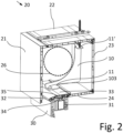
- top-mounted roller shutter box 20 which has an outer wall element 21 facing the building exterior/the environment, and an inner wall element 23 facing the building interior.
- the top-mounted roller shutter box 20 is closed off at the top by a ceiling element 22, preferably connected to a building ceiling via a connecting profile.
- a floor element 24 is provided at the bottom, which can be used as an inspection opening alternatively or in addition to the inner wall element 23.
- the side wall elements that support the roller shutter shaft are not shown.
- the adapter profile 32 is mounted on a frame profile 30 of a window or door. It has a rounded portion on the side facing the unrolled roller shutter (not shown), over which the roller shutter can slide. A seal, particularly a brush seal, is preferably also arranged here. Furthermore, the adapter profile 32 is connected to the base element 33 in a locking manner.
- a cavity 35 formed between the base element 33 and the additional reinforcement profile 34 serves to accommodate the additional reinforcement profile 34 with the mounting plate 101 of the fastening device 100 and the fastening pin 102, via which the static bracket 10 is connected to the base element 33 and indirectly thereabove to the frame profile 30.
- the static bracket 10 is formed in two parts in the illustrated embodiment with a static console element with a lower fastening tab 11 and an upper fastening tab 11', which serves as the ceiling connection.
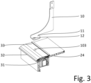
- the Figure 3 shows a perspective view of a static bracket 10 being placed on the fastening device 100.
- the static bracket 10 is shown free from the roller shutter box 20 and without contact with the base element 33.
- the static bracket 10 is arranged inside the top-mounted roller shutter box, and the lower fastening tab 11 rests loosely on the base element 33.
- the fastening opening 12 in the fastening tab and a through-hole in the base element are arranged so as to overlap.
- the Figure 3a shows a structural bracket 10 after being placed on the fastening device 100 in a top view.
- the thickened portion 103 has passed through the through-opening of the base element 33 and through the first partial opening area 13 of the fastening opening 12.
- the thickened portion 103 is located completely above the fastening tab 11.
- the diameter/cross-section of the first partial opening area 13 must be slightly larger than the diameter/cross-section of the thickened portion 103 to ensure easy placement.
- the top view shows the second partial opening area 14, which opens into the first partial opening area 13.
- This partial opening area is preferably designed as an elongated hole into which the fastening pin shaft can penetrate.
- the elongated hole or the second partial opening area 14 has a length that corresponds at least to or exactly to the displacement path required to lock the base element 33 to the adapter profile 32.
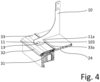
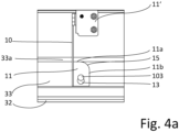
- the Figure 4 shows a static bracket 10 in the displaced state, after the edge of the fastening tab 11 surrounding the second partial opening area 14 lies under the thickening 103 and the edge at least partially surrounds the shaft of the fastening pin 102.
- the roller shutter box 20 is pushed forward, in particular this is done manually.
- the top-mounted roller shutter box 20 engages with its base element 33 over its entire length with the locking receptacle of the adapter profile 32, and at the same time, the fastening pin 102 moves with its shaft along the same locking path from the first partial opening area 13 of the fastening opening 12 in the fastening lug 11 of the static bracket 10 into the narrower second partial opening area 14, with the thickened portion 103 coming to lie above this second partial opening area 14.
- the dimensions of the second partial opening area 14, which is preferably designed as an elongated hole here, can limit the displacement path of the top-mounted roller shutter box 20, but can also be larger.
- the fastening pin 102 is preferably positively guided according to its dimensions along the length of the opening 14.
- the fastening pin 102 passes through the inlet opening 13, and the manual pushing path preferably ends through the stop in the second partial opening area 14. Since the diameter of the shaft of the fastening pin 102 approximately corresponds to the width of the second partial opening area 14 viewed perpendicular to the pushing path, lateral displacement is not possible.
- the static console 10 is connected and locked to the frame 30 after moving.
- the Figure 4 further shows that the fastening tab 11 has a stop edge 11a, which rests against a stop 33a on top of the surface of the base element 33.
- the fastening tab 11 is forced to move along with the roller shutter box 20 when it is moved, even though the fastening tab 11 is not fixed to the base element 33.
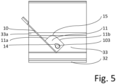
- Figure 5 shows the possibility of dismantling the static bracket 11.
- the static bracket 10 is dismantled by turning it around the fastening pin.
- the The connecting region 15 between the stop edge 11a and the perpendicularly oriented edge 11b is designed such that, in every rotational position, its distance from the central axis of the fastening pin is smaller than the distance of the stop edge 11a from the central axis. This is achieved, for example, by a quarter-circle-shaped profile of the connecting region 15, preferably with a radius smaller than the distance between the stop edge 11a and the central axis of the fastening pin 102.
- the fastening tab 11 can be decoupled from the fastening pin 102.
Landscapes
- Engineering & Computer Science (AREA)
- Structural Engineering (AREA)
- Architecture (AREA)
- Civil Engineering (AREA)
- Operating, Guiding And Securing Of Roll- Type Closing Members (AREA)
Applications Claiming Priority (1)
| Application Number | Priority Date | Filing Date | Title |
|---|---|---|---|
| DE102023132684.8A DE102023132684A1 (de) | 2023-11-23 | 2023-11-23 | Befestigungsvorrichtung für einen Aufsatzrollladenkasten, Aufsatzrollladenkasten sowie Fenster / Tür mit einem Aufsatzrollladenkasten |
Publications (1)
| Publication Number | Publication Date |
|---|---|
| EP4560106A1 true EP4560106A1 (fr) | 2025-05-28 |
Family
ID=93648364
Family Applications (1)
| Application Number | Title | Priority Date | Filing Date |
|---|---|---|---|
| EP24214667.8A Pending EP4560106A1 (fr) | 2023-11-23 | 2024-11-22 | Dispositif de fixation pour un coffre de volet roulant, coffre de volet roulant et fenêtre/porte dotée d'un coffre de volet roulant |
Country Status (2)
| Country | Link |
|---|---|
| EP (1) | EP4560106A1 (fr) |
| DE (1) | DE102023132684A1 (fr) |
Citations (4)
| Publication number | Priority date | Publication date | Assignee | Title |
|---|---|---|---|---|
| EP1705335A2 (fr) | 2005-03-04 | 2006-09-27 | Veka AG | Recouvrement pour le carter d'un volet roulant |
| EP1775415A2 (fr) | 2005-10-13 | 2007-04-18 | Veka AG | Caisson de volet roulant |
| DE202012103629U1 (de) * | 2012-09-21 | 2013-09-24 | Veka Ag | Befestigungsvorrichtung für ein Aussteifungselement eines Rollladenkastens |
| DE202016107136U1 (de) * | 2016-12-19 | 2018-03-21 | Veka Ag | Basisprofil zur Aussteifung eines Aluminium-Kunststoff-Verbundblendrahmens und zur Verbindung mit einer Statikkonsole eines Rollladenkastens |
Family Cites Families (4)
| Publication number | Priority date | Publication date | Assignee | Title |
|---|---|---|---|---|
| US4497093A (en) * | 1982-12-27 | 1985-02-05 | Haberkorn Jerome R | Two-part fastener |
| DE202013101783U1 (de) * | 2013-04-24 | 2013-07-19 | Veka Ag | Wärmegedämmtes Aussteifungselement für einen Rollladenkasten und Rolladenkasten |
| DE202014101111U1 (de) * | 2013-11-20 | 2015-02-23 | Exte-Extrudertechnik Gmbh | Rollladenkasten |
| AT519388B1 (de) * | 2016-11-17 | 2018-08-15 | Hella Sonnen Und Wetterschutztechnik Gmbh | Montagevorrichtung für einen auf einem Fensterrahmen anordenbaren Rollladenkasten |
-
2023
- 2023-11-23 DE DE102023132684.8A patent/DE102023132684A1/de active Pending
-
2024
- 2024-11-22 EP EP24214667.8A patent/EP4560106A1/fr active Pending
Patent Citations (4)
| Publication number | Priority date | Publication date | Assignee | Title |
|---|---|---|---|---|
| EP1705335A2 (fr) | 2005-03-04 | 2006-09-27 | Veka AG | Recouvrement pour le carter d'un volet roulant |
| EP1775415A2 (fr) | 2005-10-13 | 2007-04-18 | Veka AG | Caisson de volet roulant |
| DE202012103629U1 (de) * | 2012-09-21 | 2013-09-24 | Veka Ag | Befestigungsvorrichtung für ein Aussteifungselement eines Rollladenkastens |
| DE202016107136U1 (de) * | 2016-12-19 | 2018-03-21 | Veka Ag | Basisprofil zur Aussteifung eines Aluminium-Kunststoff-Verbundblendrahmens und zur Verbindung mit einer Statikkonsole eines Rollladenkastens |
Also Published As
| Publication number | Publication date |
|---|---|
| DE102023132684A1 (de) | 2025-05-28 |
Similar Documents
| Publication | Publication Date | Title |
|---|---|---|
| EP0230999B1 (fr) | Porte roulante verticale pour basses hauteurs de linteau | |
| AT397979B (de) | Rolladen | |
| EP4473182B1 (fr) | Agencement de profilé d'une fenêtre ou d'une porte ayant un profilé de châssis/battant, en particulier un profilé de châssis/battant coulissant | |
| EP2749726B1 (fr) | Dispositif de fixation pour un élément de rigidification d'un coffre de store | |
| EP4276268B1 (fr) | Portail sectionnel | |
| EP0947654A1 (fr) | Charnière cachée | |
| DE19744832C2 (de) | Anordnung für den Einbau eines Fensterrahmens | |
| EP4446557B1 (fr) | Coffre supérieur de volet roulant ainsi que planche de fond et profilé de montage de planche de fond pour cela | |
| DE102023132684A1 (de) | Befestigungsvorrichtung für einen Aufsatzrollladenkasten, Aufsatzrollladenkasten sowie Fenster / Tür mit einem Aufsatzrollladenkasten | |
| EP1001124A1 (fr) | Ferrure de charnière pour un volet | |
| DE19834700B4 (de) | Vorrichtung zum Verschließen einer Wandöffnung | |
| DE29903324U1 (de) | Rahmen eines Fensters, einer Klappe oder einer Tür an Wohnwagen, Wohnmobilen oder sonstigen Fahrzeugen | |
| DE19959736A1 (de) | Rolladen-Aufsatzkasten | |
| DE9101597U1 (de) | Scharnier | |
| EP3441557B1 (fr) | Dispositif formant portail comportant un dispostif formant porte | |
| EP4026979B1 (fr) | Installation de porte hermétique | |
| EP3115541B1 (fr) | Console structurelle de caisson de store | |
| EP4198248B1 (fr) | Bordure d'un coffre de volet roulant | |
| EP2924227B1 (fr) | Unité de palier intermédiaire pour au moins un arbre de store disposé dans un coffre de store | |
| EP2182157B1 (fr) | Ecran pour un espace entre un dormant de porte ou de portail et intrados | |
| DE10108697C2 (de) | Flügeleinrichtung mit Gelenkeinrichtung in einem Randprofil des Flügels | |
| DE19651068C1 (de) | Gliedertor | |
| EP3656955B1 (fr) | Gâche | |
| DE202024101220U1 (de) | Antriebsvorrichtung mit einer Führungsschiene für einen verschiebbaren Flügel als Schiebeflügel oder verschiebbaren Hebe-Schiebeflügel eines Fensters oder einer Tür | |
| EP4632187A1 (fr) | Porte ou fenêtre avec un dispositif de réglage pour presser un angle d'aile et / ou pour soulever une aile |
Legal Events
| Date | Code | Title | Description |
|---|---|---|---|
| PUAI | Public reference made under article 153(3) epc to a published international application that has entered the european phase |
Free format text: ORIGINAL CODE: 0009012 |
|
| STAA | Information on the status of an ep patent application or granted ep patent |
Free format text: STATUS: THE APPLICATION HAS BEEN PUBLISHED |
|
| AK | Designated contracting states |
Kind code of ref document: A1 Designated state(s): AL AT BE BG CH CY CZ DE DK EE ES FI FR GB GR HR HU IE IS IT LI LT LU LV MC ME MK MT NL NO PL PT RO RS SE SI SK SM TR |
|
| STAA | Information on the status of an ep patent application or granted ep patent |
Free format text: STATUS: REQUEST FOR EXAMINATION WAS MADE |
|
| 17P | Request for examination filed |
Effective date: 20251125 |