EP4560183A1 - Batterie-/batteriegehäuse mit sicherer und wasserdichter verriegelung und stirnlampe damit - Google Patents
Batterie-/batteriegehäuse mit sicherer und wasserdichter verriegelung und stirnlampe damit Download PDFInfo
- Publication number
- EP4560183A1 EP4560183A1 EP23315436.8A EP23315436A EP4560183A1 EP 4560183 A1 EP4560183 A1 EP 4560183A1 EP 23315436 A EP23315436 A EP 23315436A EP 4560183 A1 EP4560183 A1 EP 4560183A1
- Authority
- EP
- European Patent Office
- Prior art keywords
- cover
- rotation
- housing
- axis
- lever
- Prior art date
- Legal status (The legal status is an assumption and is not a legal conclusion. Google has not performed a legal analysis and makes no representation as to the accuracy of the status listed.)
- Pending
Links
Images






Classifications
-
- H—ELECTRICITY
- H01—ELECTRIC ELEMENTS
- H01M—PROCESSES OR MEANS, e.g. BATTERIES, FOR THE DIRECT CONVERSION OF CHEMICAL ENERGY INTO ELECTRICAL ENERGY
- H01M50/00—Constructional details or processes of manufacture of the non-active parts of electrochemical cells other than fuel cells, e.g. hybrid cells
- H01M50/20—Mountings; Secondary casings or frames; Racks, modules or packs; Suspension devices; Shock absorbers; Transport or carrying devices; Holders
- H01M50/247—Mountings; Secondary casings or frames; Racks, modules or packs; Suspension devices; Shock absorbers; Transport or carrying devices; Holders specially adapted for portable devices, e.g. mobile phones, computers, hand tools or pacemakers
-
- H—ELECTRICITY
- H01—ELECTRIC ELEMENTS
- H01R—ELECTRICALLY-CONDUCTIVE CONNECTIONS; STRUCTURAL ASSOCIATIONS OF A PLURALITY OF MUTUALLY-INSULATED ELECTRICAL CONNECTING ELEMENTS; COUPLING DEVICES; CURRENT COLLECTORS
- H01R13/00—Details of coupling devices of the kinds covered by groups H01R12/70 or H01R24/00 - H01R33/00
- H01R13/62—Means for facilitating engagement or disengagement of coupling parts or for holding them in engagement
- H01R13/627—Snap or like fastening
- H01R13/6271—Latching means integral with the housing
-
- F—MECHANICAL ENGINEERING; LIGHTING; HEATING; WEAPONS; BLASTING
- F21—LIGHTING
- F21L—LIGHTING DEVICES OR SYSTEMS THEREOF, BEING PORTABLE OR SPECIALLY ADAPTED FOR TRANSPORTATION
- F21L4/00—Electric lighting devices with self-contained electric batteries or cells
- F21L4/04—Electric lighting devices with self-contained electric batteries or cells characterised by the provision of a light source housing portion adjustably fixed to the remainder of the device
-
- F—MECHANICAL ENGINEERING; LIGHTING; HEATING; WEAPONS; BLASTING
- F21—LIGHTING
- F21V—FUNCTIONAL FEATURES OR DETAILS OF LIGHTING DEVICES OR SYSTEMS THEREOF; STRUCTURAL COMBINATIONS OF LIGHTING DEVICES WITH OTHER ARTICLES, NOT OTHERWISE PROVIDED FOR
- F21V15/00—Protecting lighting devices from damage
- F21V15/01—Housings, e.g. material or assembling of housing parts
-
- F—MECHANICAL ENGINEERING; LIGHTING; HEATING; WEAPONS; BLASTING
- F21—LIGHTING
- F21V—FUNCTIONAL FEATURES OR DETAILS OF LIGHTING DEVICES OR SYSTEMS THEREOF; STRUCTURAL COMBINATIONS OF LIGHTING DEVICES WITH OTHER ARTICLES, NOT OTHERWISE PROVIDED FOR
- F21V17/00—Fastening of component parts of lighting devices, e.g. shades, globes, refractors, reflectors, filters, screens, grids or protective cages
- F21V17/10—Fastening of component parts of lighting devices, e.g. shades, globes, refractors, reflectors, filters, screens, grids or protective cages characterised by specific fastening means or way of fastening
- F21V17/18—Latch-type fastening, e.g. with rotary action
-
- F—MECHANICAL ENGINEERING; LIGHTING; HEATING; WEAPONS; BLASTING
- F21—LIGHTING
- F21V—FUNCTIONAL FEATURES OR DETAILS OF LIGHTING DEVICES OR SYSTEMS THEREOF; STRUCTURAL COMBINATIONS OF LIGHTING DEVICES WITH OTHER ARTICLES, NOT OTHERWISE PROVIDED FOR
- F21V21/00—Supporting, suspending, or attaching arrangements for lighting devices; Hand grips
- F21V21/08—Devices for easy attachment to any desired place, e.g. clip, clamp, magnet
- F21V21/084—Head fittings
-
- H—ELECTRICITY
- H01—ELECTRIC ELEMENTS
- H01M—PROCESSES OR MEANS, e.g. BATTERIES, FOR THE DIRECT CONVERSION OF CHEMICAL ENERGY INTO ELECTRICAL ENERGY
- H01M10/00—Secondary cells; Manufacture thereof
- H01M10/42—Methods or arrangements for servicing or maintenance of secondary cells or secondary half-cells
- H01M10/46—Accumulators structurally combined with charging apparatus
-
- H—ELECTRICITY
- H01—ELECTRIC ELEMENTS
- H01M—PROCESSES OR MEANS, e.g. BATTERIES, FOR THE DIRECT CONVERSION OF CHEMICAL ENERGY INTO ELECTRICAL ENERGY
- H01M50/00—Constructional details or processes of manufacture of the non-active parts of electrochemical cells other than fuel cells, e.g. hybrid cells
- H01M50/20—Mountings; Secondary casings or frames; Racks, modules or packs; Suspension devices; Shock absorbers; Transport or carrying devices; Holders
- H01M50/262—Mountings; Secondary casings or frames; Racks, modules or packs; Suspension devices; Shock absorbers; Transport or carrying devices; Holders with fastening means, e.g. locks
-
- H—ELECTRICITY
- H01—ELECTRIC ELEMENTS
- H01R—ELECTRICALLY-CONDUCTIVE CONNECTIONS; STRUCTURAL ASSOCIATIONS OF A PLURALITY OF MUTUALLY-INSULATED ELECTRICAL CONNECTING ELEMENTS; COUPLING DEVICES; CURRENT COLLECTORS
- H01R13/00—Details of coupling devices of the kinds covered by groups H01R12/70 or H01R24/00 - H01R33/00
- H01R13/62—Means for facilitating engagement or disengagement of coupling parts or for holding them in engagement
- H01R13/629—Additional means for facilitating engagement or disengagement of coupling parts, e.g. aligning or guiding means, levers, gas pressure electrical locking indicators, manufacturing tolerances
- H01R13/62905—Additional means for facilitating engagement or disengagement of coupling parts, e.g. aligning or guiding means, levers, gas pressure electrical locking indicators, manufacturing tolerances comprising a camming member
- H01R13/62911—U-shaped sliding element
-
- H—ELECTRICITY
- H01—ELECTRIC ELEMENTS
- H01M—PROCESSES OR MEANS, e.g. BATTERIES, FOR THE DIRECT CONVERSION OF CHEMICAL ENERGY INTO ELECTRICAL ENERGY
- H01M2220/00—Batteries for particular applications
- H01M2220/30—Batteries in portable systems, e.g. mobile phone, laptop
Definitions
- the present invention relates to the field of portable electric lamps and in particular, a battery box provided with a secure and waterproof lock intended for the production of a headlamp.
- Portable headlamps often have a battery compartment, either internal or external, depending on whether the weight of the batteries is to be transferred to the rear.
- these headlamps are intended to be used at all times and in all conditions, so their batteries and/or cells must be able to be kept in a secure and waterproof housing.
- a box is often used with a cover that can be locked onto the box once the batteries are in place by various mechanisms and devices.
- the housing comprises at the middle of the left and right side faces two pivot elements producing a third axis of rotation around which the housing can describe a rotational movement relative to a fixed support.
- the assembly of the hinge is carried out by means of two blind holes materializing the first axis of rotation and configured to receive two rods/pins of said cover.
- the lever is configured so as to perfectly match the shape and profile of said cover (20) when the latter is in the finalized locking position.
- the battery box In order to reduce the weight of the load carried in front of the user's head, the battery box is designed to be moved to the back of the user's head in order to power a headlamp electronic circuit located in front of the user.
- the housing and its locking system are designed to be completely independent of the LED lighting system and its associated electronics. Consequently, the housing that will be described can be associated with any lighting system, from the simplest to the most sophisticated, such as, for example, that of lighting incorporating REACTIVE LIGHTING technology marketed by the company PETZL, or any lighting whatsoever.
- the housing according to the invention comprises a housing body 10 of substantially parallelepipedal shape - illustrated in both the front and rear perspectives of the Figures 1a and 1b respectively, and intended to receive a housing for cells and/or a battery.
- the housing body 10 comprises a front face 11, a rear face 12 and two left 13 and right 14 side faces which delimit by means of an associated bottom a housing for a set of batteries and/or a power supply battery.
- the rear face 12 comprises, at its upper rear edge, a connection system 19 with a cover 20, of hinge type, allowing the rotation of the cover 20 relative to a first axis of rotation substantially parallel to the upper rear edge of the housing.
- the assembly of the hinge is carried out at the level of the housing by means of two blind holes materializing the first axis of rotation and configured to receive two rods/pins of the cover 20 which will be described later.
- Each of the left 13 and right 14 side faces comprises, at the level of the front part of the housing, a groove of substantially circular shape, centered on a point defining a second axis of rotation , the functionality of which will be described later.
- the housing comprises at the middle of the left and right side faces two pivot elements 17 and 18 producing a third axis of rotation 17-18, around which the housing can describe a rotational movement relative to a fixed support not illustrated in the Figures 1a and 1b .
- the cover 20 which is configured so as to close, in a sealed manner, the housing of the Figure 1a and 1b .
- the cover 19 comprises an upper face, two left and right side faces and a rear face.
- the rear side face comprises two blind holes 21 and 22 sharing the common axis of the hinge 19, and intended to receive a rotation rod (not described) for producing a pivot connection between the cover 20 and the housing 10.
- the cover comprises respectively in its upper part and on the left and right lateral faces of the cover 20 a circular hole, respectively 23 and 24, materializing the second axis of rotation mentioned previously , and configured to receive two pins 33 and 34 located on the two ends of a U-shaped lever 30, so as to allow its rotation around the second axis of rotation located at the front of the cover 20.
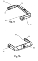
- the lever 30, illustrated in the Figures 3a and 3b is configured so as to perfectly match the shape and profile of the cover 20 when the latter is in a horizontal plane, finalizing the locking
- the U-shaped lever 30 is illustrated more specifically in the Figures 3a and 3b and comprises respectively two branches 31 (left) and 32 (right).
- the inner face of the branch 31 comprises at its end a first perpendicular pin 33 while the branch 32 comprises on its inner face a second pin 34 also at its end.
- the two pins 33 and 34 are intended to be inserted into the blind holes 23 and 24, respectively of the cover 20 so as to provide the pivot connection of the lever 30 relative to the cover 20 along the second axis of rotation.
- the U-shaped lever 30 also comprises, on each of the two external faces of the branches 31 and 32, a semi-circular cam, 35 and 36 respectively, having a substantially circular shape around an axis common with the second axis of rotation.
- the side faces 13 and 14 of the housing 10 comprise, at the level of the front part, two circular grooves 15 and 16 configured to receive the passage of the semi-circular cams 35 and 36, respectively, when the cover is in the closed position with the lever in a vertical plane as illustrated in Figure 6a , and that we lower the lever to the right to bring it into a horizontal plane ( Figure 6b and Figure 6c ), which causes the semi-circular cams 35/36 to be inserted into their respective circular grooves 15 and 16 and ensures force locking through the cooperation between the semi-circular cams 35/36 and the circular grooves 15/16.
- FIG. 4a is a view showing a headlamp comprising a housing, its cover and the locking lever mounted on a support 100.
- Two sectional views, respectively CAM-CAM and LEVER-LEVER are defined therein.
- FIG. 4b is a section of the headlamp following the CAM-CAM axis of the Figure 4a .
- FIG. 5a is a section along the LEVER-LEVER axis of the Figure 4a , also highlighting an AXE_LEVIER-AXE_LEVIER section, the detail of which is illustrated in Figure 5a .
- FIGS. 6a, 6b and 6c show three illustrative sections of the hood locking by means of the locking lever, this locking lever being located in three different positions: open, semi-open, and closed (locked). It can be clearly seen that lowering the lever makes it possible to achieve the assembly described above between the cams 35/36 and the circular grooves 15/16, so as to ensure a tight and effective closing of the cover. It will be noted in particular that perfect sealing can be achieved by means of one or more seals arranged on the cover, the details of which are not part of the present invention.
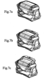
- FIG. 7a-7f illustrate perspective views of the different phases of unlocking the cover.
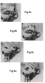
- FIGS. 8a-8gf illustrate the different phases of closing the waterproof case by a user, highlighting the double rotation exerted when locking the case.
- Figure 8a shows the open case, in which a set of three stick batteries has been housed.
Landscapes
- Engineering & Computer Science (AREA)
- General Engineering & Computer Science (AREA)
- General Chemical & Material Sciences (AREA)
- Chemical & Material Sciences (AREA)
- Chemical Kinetics & Catalysis (AREA)
- Electrochemistry (AREA)
- Manufacturing & Machinery (AREA)
- Life Sciences & Earth Sciences (AREA)
- Biophysics (AREA)
- Computer Hardware Design (AREA)
- Charge And Discharge Circuits For Batteries Or The Like (AREA)
- Casings For Electric Apparatus (AREA)
- Lighting Device Outwards From Vehicle And Optical Signal (AREA)
Priority Applications (5)
| Application Number | Priority Date | Filing Date | Title |
|---|---|---|---|
| EP23315436.8A EP4560183A1 (de) | 2023-11-21 | 2023-11-21 | Batterie-/batteriegehäuse mit sicherer und wasserdichter verriegelung und stirnlampe damit |
| EP24157980.4A EP4560182A1 (de) | 2023-11-21 | 2024-02-15 | Universelle elektrische verbindungsvorrichtung für ein batteriegehäuse und/oder eine batterie |
| CN202422846821.9U CN224021082U (zh) | 2023-11-21 | 2024-11-21 | 用于电池充电系统的连接装置、对头灯的电池进行充电的充电装置、头灯以及为便携式灯供电的电池 |
| US18/955,192 US20250167489A1 (en) | 2023-11-21 | 2024-11-21 | Universal Electrical Connection Device for a Battery Box and/or a Battery |
| CN202422847441.7U CN223785231U (zh) | 2023-11-21 | 2024-11-21 | 用于头灯的电池容纳盒和包括该电池容纳盒的头灯 |
Applications Claiming Priority (1)
| Application Number | Priority Date | Filing Date | Title |
|---|---|---|---|
| EP23315436.8A EP4560183A1 (de) | 2023-11-21 | 2023-11-21 | Batterie-/batteriegehäuse mit sicherer und wasserdichter verriegelung und stirnlampe damit |
Publications (1)
| Publication Number | Publication Date |
|---|---|
| EP4560183A1 true EP4560183A1 (de) | 2025-05-28 |
Family
ID=89426634
Family Applications (2)
| Application Number | Title | Priority Date | Filing Date |
|---|---|---|---|
| EP23315436.8A Pending EP4560183A1 (de) | 2023-11-21 | 2023-11-21 | Batterie-/batteriegehäuse mit sicherer und wasserdichter verriegelung und stirnlampe damit |
| EP24157980.4A Pending EP4560182A1 (de) | 2023-11-21 | 2024-02-15 | Universelle elektrische verbindungsvorrichtung für ein batteriegehäuse und/oder eine batterie |
Family Applications After (1)
| Application Number | Title | Priority Date | Filing Date |
|---|---|---|---|
| EP24157980.4A Pending EP4560182A1 (de) | 2023-11-21 | 2024-02-15 | Universelle elektrische verbindungsvorrichtung für ein batteriegehäuse und/oder eine batterie |
Country Status (3)
| Country | Link |
|---|---|
| US (1) | US20250167489A1 (de) |
| EP (2) | EP4560183A1 (de) |
| CN (2) | CN223785231U (de) |
Citations (3)
| Publication number | Priority date | Publication date | Assignee | Title |
|---|---|---|---|---|
| EP2299516A1 (de) * | 2009-08-24 | 2011-03-23 | GARDENA Manufacturing GmbH | Batteriebetriebenes Gerät und Batterie dafür |
| DE102019218525A1 (de) * | 2019-11-29 | 2021-06-02 | Robert Bosch Gmbh | Energieversorgungsvorrichtung für eine Gartenpumpe und Gartenpumpe damit |
| US20220294066A1 (en) * | 2021-03-10 | 2022-09-15 | Andrew G. C. Frazier | Portable battery containers |
Family Cites Families (2)
| Publication number | Priority date | Publication date | Assignee | Title |
|---|---|---|---|---|
| US6236187B1 (en) * | 2000-09-27 | 2001-05-22 | Tsung-Ming Chen | Plug-in charging battery module |
| US20160146443A1 (en) * | 2013-06-17 | 2016-05-26 | Steiner Marketing Gmbh | Headlamp with separate battery module and lighting module connected by cable |
-
2023
- 2023-11-21 EP EP23315436.8A patent/EP4560183A1/de active Pending
-
2024
- 2024-02-15 EP EP24157980.4A patent/EP4560182A1/de active Pending
- 2024-11-21 CN CN202422847441.7U patent/CN223785231U/zh active Active
- 2024-11-21 CN CN202422846821.9U patent/CN224021082U/zh active Active
- 2024-11-21 US US18/955,192 patent/US20250167489A1/en active Pending
Patent Citations (3)
| Publication number | Priority date | Publication date | Assignee | Title |
|---|---|---|---|---|
| EP2299516A1 (de) * | 2009-08-24 | 2011-03-23 | GARDENA Manufacturing GmbH | Batteriebetriebenes Gerät und Batterie dafür |
| DE102019218525A1 (de) * | 2019-11-29 | 2021-06-02 | Robert Bosch Gmbh | Energieversorgungsvorrichtung für eine Gartenpumpe und Gartenpumpe damit |
| US20220294066A1 (en) * | 2021-03-10 | 2022-09-15 | Andrew G. C. Frazier | Portable battery containers |
Also Published As
| Publication number | Publication date |
|---|---|
| US20250167489A1 (en) | 2025-05-22 |
| EP4560182A1 (de) | 2025-05-28 |
| CN223785231U (zh) | 2026-01-09 |
| CN224021082U (zh) | 2026-03-20 |
Similar Documents
| Publication | Publication Date | Title |
|---|---|---|
| EP0619628B1 (de) | Elektrische Verbinder insbesondere Verbinder zum Laden von Akkus | |
| EP0880915A1 (de) | Behälter für kosmetische Produkten, Puderdose und Verfahren zum Öffnen und Schliessen | |
| FR2972081A1 (fr) | Dispositif de charge de batteries d'alimentation d'un vehicule automobile a moyen de securisation du pistolet de charge a sa position branchee de charge des batteries | |
| FR2791621A1 (fr) | Dispositif de rangement de casque pour motocyclette | |
| FR2736025A1 (fr) | Essuie-glace pour vehicule automobile comportant un connecteur muni d'un capot articule | |
| FR2774519A1 (fr) | Pilier d'angle pour armoire destinee a loger de l'appareillage electrique et armoire equipee d'un tel pilier | |
| EP4560183A1 (de) | Batterie-/batteriegehäuse mit sicherer und wasserdichter verriegelung und stirnlampe damit | |
| FR3098765A1 (fr) | Trappe de recharge ou de reservoir et procede de fabrication de celle-ci | |
| EP0688692A1 (de) | Schwenkbarer Tankverschlussdeckel für Personenkraftwagen | |
| EP0897679A1 (de) | Dose mit lösbarem Scharnier und Dichtungslippe | |
| FR3157285A1 (fr) | Module de trappe d’accès à une interface d’alimentation ou de chargement d’un véhicule automobile. | |
| FR3107700A1 (fr) | Boitier, notamment pour produits cosmetiques | |
| FR2625141A1 (fr) | Goulotte de remplissage de carburant equipee d'un dispositif de fermeture perfectionne commande de l'interieur du vehicule | |
| EP1388447A1 (de) | Laderaumtür und Nutzfahrzeug mit mindestens einer solchen Tür ausgerüstet | |
| FR3105621A1 (fr) | Boîte électrique munie d’un joint d’étanchéité | |
| FR2821800A1 (fr) | Dispositif de remplissage de reservoir a carburant | |
| EP2623694B1 (de) | Einheit zur Herstellung von elektromagnetischen Bändern verschiedener Höhe | |
| EP4707507A1 (de) | Verriegelungsvorrichtung für eine haubenanordnung | |
| EP0704650B1 (de) | Dichtring für Kabel, Rohre oder dergleichen und seine Verwendung an einem elektrischen Anschlussgehäuse | |
| FR2696154A1 (fr) | Boîte en carton à couvercle intégré. | |
| WO2007017560A1 (fr) | Dispositif dεtancheite de connecteur | |
| FR2686061A1 (fr) | Caisse en matiere plastique moulee equipee d'un abattant. | |
| EP1227559A1 (de) | Anordnung einer elektrischen Anschlussvorrichtung für eine Einbauleuchte | |
| EP0869245B1 (de) | Beschlag für Schiebetür, Schiebefenster oder ähnliches | |
| FR3165553A1 (fr) | Réceptacle pour produit, notamment cosmétique |
Legal Events
| Date | Code | Title | Description |
|---|---|---|---|
| PUAI | Public reference made under article 153(3) epc to a published international application that has entered the european phase |
Free format text: ORIGINAL CODE: 0009012 |
|
| STAA | Information on the status of an ep patent application or granted ep patent |
Free format text: STATUS: THE APPLICATION HAS BEEN PUBLISHED |
|
| STAA | Information on the status of an ep patent application or granted ep patent |
Free format text: STATUS: REQUEST FOR EXAMINATION WAS MADE |
|
| AK | Designated contracting states |
Kind code of ref document: A1 Designated state(s): AL AT BE BG CH CY CZ DE DK EE ES FI FR GB GR HR HU IE IS IT LI LT LU LV MC ME MK MT NL NO PL PT RO RS SE SI SK SM TR |
|
| 17P | Request for examination filed |
Effective date: 20250515 |