EP4560185A1 - Dispositif d'éclairage pour un phare de véhicule automobile et phare de véhicule automobile - Google Patents
Dispositif d'éclairage pour un phare de véhicule automobile et phare de véhicule automobile Download PDFInfo
- Publication number
- EP4560185A1 EP4560185A1 EP23211767.1A EP23211767A EP4560185A1 EP 4560185 A1 EP4560185 A1 EP 4560185A1 EP 23211767 A EP23211767 A EP 23211767A EP 4560185 A1 EP4560185 A1 EP 4560185A1
- Authority
- EP
- European Patent Office
- Prior art keywords
- light
- lighting device
- coupling element
- deflection structure
- boundary surface
- Prior art date
- Legal status (The legal status is an assumption and is not a legal conclusion. Google has not performed a legal analysis and makes no representation as to the accuracy of the status listed.)
- Granted
Links
Images


Classifications
-
- F—MECHANICAL ENGINEERING; LIGHTING; HEATING; WEAPONS; BLASTING
- F21—LIGHTING
- F21S—NON-PORTABLE LIGHTING DEVICES; SYSTEMS THEREOF; VEHICLE LIGHTING DEVICES SPECIALLY ADAPTED FOR VEHICLE EXTERIORS
- F21S41/00—Illuminating devices specially adapted for vehicle exteriors, e.g. headlamps
- F21S41/20—Illuminating devices specially adapted for vehicle exteriors, e.g. headlamps characterised by refractors, transparent cover plates, light guides or filters
- F21S41/285—Refractors, transparent cover plates, light guides or filters not provided in groups F21S41/24 - F21S41/2805
-
- F—MECHANICAL ENGINEERING; LIGHTING; HEATING; WEAPONS; BLASTING
- F21—LIGHTING
- F21S—NON-PORTABLE LIGHTING DEVICES; SYSTEMS THEREOF; VEHICLE LIGHTING DEVICES SPECIALLY ADAPTED FOR VEHICLE EXTERIORS
- F21S41/00—Illuminating devices specially adapted for vehicle exteriors, e.g. headlamps
- F21S41/30—Illuminating devices specially adapted for vehicle exteriors, e.g. headlamps characterised by reflectors
- F21S41/32—Optical layout thereof
- F21S41/322—Optical layout thereof the reflector using total internal reflection
-
- F—MECHANICAL ENGINEERING; LIGHTING; HEATING; WEAPONS; BLASTING
- F21—LIGHTING
- F21S—NON-PORTABLE LIGHTING DEVICES; SYSTEMS THEREOF; VEHICLE LIGHTING DEVICES SPECIALLY ADAPTED FOR VEHICLE EXTERIORS
- F21S41/00—Illuminating devices specially adapted for vehicle exteriors, e.g. headlamps
- F21S41/20—Illuminating devices specially adapted for vehicle exteriors, e.g. headlamps characterised by refractors, transparent cover plates, light guides or filters
- F21S41/24—Light guides
-
- F—MECHANICAL ENGINEERING; LIGHTING; HEATING; WEAPONS; BLASTING
- F21—LIGHTING
- F21S—NON-PORTABLE LIGHTING DEVICES; SYSTEMS THEREOF; VEHICLE LIGHTING DEVICES SPECIALLY ADAPTED FOR VEHICLE EXTERIORS
- F21S41/00—Illuminating devices specially adapted for vehicle exteriors, e.g. headlamps
- F21S41/10—Illuminating devices specially adapted for vehicle exteriors, e.g. headlamps characterised by the light source
- F21S41/14—Illuminating devices specially adapted for vehicle exteriors, e.g. headlamps characterised by the light source characterised by the type of light source
- F21S41/141—Light emitting diodes [LED]
- F21S41/143—Light emitting diodes [LED] the main emission direction of the LED being parallel to the optical axis of the illuminating device
-
- F—MECHANICAL ENGINEERING; LIGHTING; HEATING; WEAPONS; BLASTING
- F21—LIGHTING
- F21S—NON-PORTABLE LIGHTING DEVICES; SYSTEMS THEREOF; VEHICLE LIGHTING DEVICES SPECIALLY ADAPTED FOR VEHICLE EXTERIORS
- F21S41/00—Illuminating devices specially adapted for vehicle exteriors, e.g. headlamps
- F21S41/20—Illuminating devices specially adapted for vehicle exteriors, e.g. headlamps characterised by refractors, transparent cover plates, light guides or filters
- F21S41/25—Projection lenses
- F21S41/27—Thick lenses
-
- F—MECHANICAL ENGINEERING; LIGHTING; HEATING; WEAPONS; BLASTING
- F21—LIGHTING
- F21S—NON-PORTABLE LIGHTING DEVICES; SYSTEMS THEREOF; VEHICLE LIGHTING DEVICES SPECIALLY ADAPTED FOR VEHICLE EXTERIORS
- F21S41/00—Illuminating devices specially adapted for vehicle exteriors, e.g. headlamps
- F21S41/20—Illuminating devices specially adapted for vehicle exteriors, e.g. headlamps characterised by refractors, transparent cover plates, light guides or filters
- F21S41/25—Projection lenses
- F21S41/275—Lens surfaces, e.g. coatings or surface structures
-
- F—MECHANICAL ENGINEERING; LIGHTING; HEATING; WEAPONS; BLASTING
- F21—LIGHTING
- F21S—NON-PORTABLE LIGHTING DEVICES; SYSTEMS THEREOF; VEHICLE LIGHTING DEVICES SPECIALLY ADAPTED FOR VEHICLE EXTERIORS
- F21S41/00—Illuminating devices specially adapted for vehicle exteriors, e.g. headlamps
- F21S41/30—Illuminating devices specially adapted for vehicle exteriors, e.g. headlamps characterised by reflectors
- F21S41/32—Optical layout thereof
-
- F—MECHANICAL ENGINEERING; LIGHTING; HEATING; WEAPONS; BLASTING
- F21—LIGHTING
- F21S—NON-PORTABLE LIGHTING DEVICES; SYSTEMS THEREOF; VEHICLE LIGHTING DEVICES SPECIALLY ADAPTED FOR VEHICLE EXTERIORS
- F21S41/00—Illuminating devices specially adapted for vehicle exteriors, e.g. headlamps
- F21S41/40—Illuminating devices specially adapted for vehicle exteriors, e.g. headlamps characterised by screens, non-reflecting members, light-shielding members or fixed shades
- F21S41/43—Illuminating devices specially adapted for vehicle exteriors, e.g. headlamps characterised by screens, non-reflecting members, light-shielding members or fixed shades characterised by the shape thereof
-
- F—MECHANICAL ENGINEERING; LIGHTING; HEATING; WEAPONS; BLASTING
- F21—LIGHTING
- F21W—INDEXING SCHEME ASSOCIATED WITH SUBCLASSES F21K, F21L, F21S and F21V, RELATING TO USES OR APPLICATIONS OF LIGHTING DEVICES OR SYSTEMS
- F21W2102/00—Exterior vehicle lighting devices for illuminating purposes
-
- F—MECHANICAL ENGINEERING; LIGHTING; HEATING; WEAPONS; BLASTING
- F21—LIGHTING
- F21W—INDEXING SCHEME ASSOCIATED WITH SUBCLASSES F21K, F21L, F21S and F21V, RELATING TO USES OR APPLICATIONS OF LIGHTING DEVICES OR SYSTEMS
- F21W2102/00—Exterior vehicle lighting devices for illuminating purposes
- F21W2102/10—Arrangement or contour of the emitted light
- F21W2102/13—Arrangement or contour of the emitted light for high-beam region or low-beam region
- F21W2102/135—Arrangement or contour of the emitted light for high-beam region or low-beam region the light having cut-off lines, i.e. clear borderlines between emitted regions and dark regions
- F21W2102/14—Arrangement or contour of the emitted light for high-beam region or low-beam region the light having cut-off lines, i.e. clear borderlines between emitted regions and dark regions having vertical cut-off lines; specially adapted for adaptive high beams, i.e. wherein the beam is broader but avoids glaring other road users
- F21W2102/15—Arrangement or contour of the emitted light for high-beam region or low-beam region the light having cut-off lines, i.e. clear borderlines between emitted regions and dark regions having vertical cut-off lines; specially adapted for adaptive high beams, i.e. wherein the beam is broader but avoids glaring other road users wherein the light is emitted under L-shaped cut-off lines, i.e. vertical and horizontal cutoff lines
-
- F—MECHANICAL ENGINEERING; LIGHTING; HEATING; WEAPONS; BLASTING
- F21—LIGHTING
- F21W—INDEXING SCHEME ASSOCIATED WITH SUBCLASSES F21K, F21L, F21S and F21V, RELATING TO USES OR APPLICATIONS OF LIGHTING DEVICES OR SYSTEMS
- F21W2102/00—Exterior vehicle lighting devices for illuminating purposes
- F21W2102/10—Arrangement or contour of the emitted light
- F21W2102/17—Arrangement or contour of the emitted light for regions other than high beam or low beam
- F21W2102/18—Arrangement or contour of the emitted light for regions other than high beam or low beam for overhead signs
-
- F—MECHANICAL ENGINEERING; LIGHTING; HEATING; WEAPONS; BLASTING
- F21—LIGHTING
- F21W—INDEXING SCHEME ASSOCIATED WITH SUBCLASSES F21K, F21L, F21S and F21V, RELATING TO USES OR APPLICATIONS OF LIGHTING DEVICES OR SYSTEMS
- F21W2107/00—Use or application of lighting devices on or in particular types of vehicles
- F21W2107/10—Use or application of lighting devices on or in particular types of vehicles for land vehicles
-
- F—MECHANICAL ENGINEERING; LIGHTING; HEATING; WEAPONS; BLASTING
- F21—LIGHTING
- F21Y—INDEXING SCHEME ASSOCIATED WITH SUBCLASSES F21K, F21L, F21S and F21V, RELATING TO THE FORM OR THE KIND OF THE LIGHT SOURCES OR OF THE COLOUR OF THE LIGHT EMITTED
- F21Y2115/00—Light-generating elements of semiconductor light sources
- F21Y2115/10—Light-emitting diodes [LED]
Definitions
- the invention relates to a motor vehicle headlight with at least one such lighting device.
- the lighting devices described above are known from the prior art, in which, by modifying the light-transmitting body, the light coupling element or the projection device, a signlight light distribution can be generated in addition to a front-end or low-beam light distribution with the at least one light source.
- the light coupling element has a first deflection structure which is designed such that light from the at least one light source which enters the light coupling element and impinges on the deflection structure is totally reflected in such a way that the totally reflected light is directed onto a second deflection structure, wherein the second deflection structure is arranged on an upper boundary surface of the light-conducting body which is opposite the lower boundary surfaces, and wherein the second deflection structure is designed such that the light impinging on it is directed onto a first surface area of the first lower boundary surface of the Aperture device, which first lower boundary surface is arranged after the second boundary surface of the diaphragm device as seen in the direction of light propagation, is deflected as a fourth light beam, and wherein the surface area deflects the light incident on it as a fifth light beam into a region of the projection device which images the light of the fifth light beam as a signlight light beam into a region
- the invention realizes an optical path exclusively within the light-guiding body for generating the signlight, so that the described problems of the prior art, such as uncontrollable scattered light, which for example leads to excessive light in the area of the HV line, can be avoided.
- the signlight light distribution can be easily controlled without having a negative impact on the apron or low beam distribution.
- the first deflection structure comprises a deflection surface or is designed in the form of a deflection surface, wherein, for example, the deflection surface is designed as a flat surface or as a concavely curved surface.
- a concave curvature can, for example, be used to generate a parallel beam bundle which impinges on the second deflection structure at the upper boundary surface in an evenly distributed manner, thus allowing better control of the intensities.
- the second deflection structure is designed as a surface, in particular as a flat surface.
- the first surface area of the first lower surface forms a straight cutting curve in vertical sections.
- the first surface area of the first lower surface forms curved cutting curves, in particular convex cutting curves, in horizontal sections.
- these convex intersection curves follow a Petzval surface or focal surface of the projection device.
- Horizontal intersection curves result from intersecting the respective surface with horizontal planes
- vertical intersection curves result from intersecting the respective surface with vertical planes which run parallel to the optical axis of the lighting device or the projection device or contain the optical axis.
- the first surface area is a boundary surface of a depression in the first lower boundary surface.
- a third surface area of the first boundary surface adjoins it.
- this second surface area is positioned in such a way that no light from the second deflection structure reaches it.
- the first surface area is spaced apart from the second boundary surface and that between the first surface area and the second boundary surface, a further, second surface region of the first boundary surface is arranged, which connects the first surface region with the second boundary surface.
- the second surface area is arranged and designed in such a way that no light from the second deflection structure reaches the second surface area.
- this second surface area which for example forms a strip between the first surface area and the second boundary surface, a dark stripe can be realized in the light image, between the light-dark boundary of the apron or dipped beam distribution and the lower boundary of the signlight light distribution.
- the second deflection structure is formed by a recess in the upper boundary surface.
- This recess is formed by the preferably flat surface and, if applicable, by a further boundary surface or further boundary surfaces which are facing away from the light source and which are generally not struck by light or which have no lighting function.
- the aperture edge lies in or substantially in the Petzval surface or a focal surface of the projection device.
- the at least one light coupling element, the light-transmitting body and the projection device are formed in one piece from a light-transmitting material and together form a body.
- the light distribution with cut-off line is preferably an apron light distribution or a dipped beam distribution.
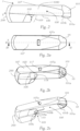
- Figures 1 and 1a show, for the time being, a lighting device 1 for a motor vehicle headlight according to the prior art for generating a light distribution LV with a cut-off line HDG.
- This light distribution is, for example, an approach beam or dipped beam distribution.
- the invention is based on such a known lighting device 1 from the prior art; corresponding technical features of the lighting device according to the prior art and the lighting device according to the invention are therefore identified by identical reference numerals.
- the lighting device 1 comprises a light-transmissive body 100, a light coupling element 101, and a light source 10 associated with the at least one light coupling element 101.
- the light emitted by the light source 10 is coupled into the light-transmissive body 100 by the light coupling element 101 and propagates in the direction of a projection device 200 of the lighting device 1.
- the light source 10 is, for example, one or more LEDs or the light source 10 comprises one or more LEDs.
- the projection device 200 is located, for example, opposite the light coupling element 101.
- the light coupling element 101 is configured to couple at least a portion of the light emitted by the light source 10 into the light-transmissive body 100 in such a way that it propagates therein as the first light beam S1 to the projection device 200.
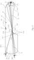
- the light-transmissive body 100 has a diaphragm device 103 with a diaphragm edge 104, wherein the diaphragm edge 104 is arranged between the light coupling element 101 and the projection device 200, as seen in the light propagation direction X1.
- the first light beam S1 is modified by the aperture edge 104 into a second light beam S2, which second light beam S2 is imaged by the projection device 200 as the light distribution LV with the cut-off line HDG.
- the cut-off line HDG in particular the shape of the cut-off line HDG, is determined by the aperture edge 104.
- the light rays of the light beam S2 are modified by the projection device 200 into light beam S2'.
- the aperture edge 104 is formed by a first lower boundary surface 105 and a second lower boundary surface 106 of the translucent body 100, which are opposite an upper boundary surface 107, in that the lower boundary surfaces 105, 106 converge in a common edge, the aperture edge 104.
- the aperture edge 104 lies in or substantially in the Petzval surface or a focal surface of the projection device 200.
- the light coupling element 101 forms the light emitted by the light source and coupled into the light coupling element into the first light beam, wherein the light beam is preferably directed into a region, in particular into a region above, preferably just above the diaphragm edge.
- the diaphragm edge is curved in the horizontal direction, in particular concavely curved, and the diaphragm edge preferably follows the focal point line of the projection device, wherein the diaphragm edge preferably lies in or approximately in the Petzval surface of the projection device.
- the projection device has a focal point F200, which lies on the optical axis X of the projection device 200.
- the Petzval surface or focal point surface contains this focal point F200, just as a focal line runs through this focal point and lies in the Petzval surface.
- the aperture edge 104 basically regardless of whether it is a straight aperture edge as in Figure 1 shown or a curved edge, e.g. curved as described above - is generally not located exactly in the Petzval surface or at the focal point F200, but at a (small) distance above the focal point 200.
- the cut-off line HDG in the light image is lowered slightly below the horizontal 0°-0° line or below the horizon, usually by 0.573°.
- the diaphragm edge 104 is located slightly in the vertical direction, in practice usually by a few tenths of a millimeter, above the optical axis X of the projection device 200 or above the focal point F200.
- the light coupling element 101, the light-transmitting body 100 and the projection device 200 are formed in one piece from a light-transmitting material and together form a body 1000.
- the light coupling element 101 has a first deflection structure 101a, which is designed such that light from the light source 10, which enters the light coupling element 101 and impinges on the deflection structure 101a, is totally reflected such that the totally reflected light S3 is directed onto a second deflection structure 107a.
- the second deflection structure 107a is arranged on the upper boundary surface 107 of the light-conducting body 100, opposite the lower boundary surfaces 105, 106.
- light coupling element 101, light-conducting body 100 and projection device 200 form a continuous, one-piece body 1000.
- the transparent, translucent material from which the individual elements, or in the case of the The one-piece body 1000 of these bodies 1000 can be formed, has a refractive index greater than that of air.
- the material contains, for example, PMMA (polymethyl methacrylate) or PC (polycarbonate) and is particularly preferably formed therefrom.
- the bodies can also be made of glass material, in particular inorganic glass material.
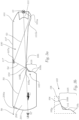
- Figure 3 shows a ray path analogous to Figure 1a , ie the ray path of light rays, which form the light distribution with cut-off line HDG. According to the invention, how this Figure 3a shows, a part of the light rays emitted by the light source 10 and entering the light coupling element 101 is used to form a signlight light distribution SV.
- the second deflection structure 107a is configured such that the light S3 incident upon it impinges upon a first surface region 105a of the first lower boundary surface 105.
- the first lower boundary surface 105 is the boundary surface which, viewed in the direction of light propagation, is arranged after the second boundary surface 106, or the diaphragm edge 104.
- the second deflection structure 107a deflects the incident light rays S3 as a fourth light beam S4 (or the incident light rays S3 are totally reflected at the deflection structure 107a).
- the surface area 105a redirects the light incident on it as a fifth light beam S5 into an area 200a of the projection device 200, specifically into an area 200a on the light-refracting light exit surface 201 of the projection device, which area 200a images the light of the fifth light beam S5 as a signlight light beam S6 into an area B of the light distribution lying above the cut-off line HDG as an additional light distribution, namely as a signlight light distribution SV.
- the first deflection structure 101a is preferably, as shown, designed in the form of a deflection surface, wherein the deflection surface is, for example, a flat surface or preferably, as shown, a concavely curved surface.
- a concave curvature can be used, for example, to generate a parallel beam bundle which impinges on the second deflection structure 107a at the upper boundary surface 107 in an evenly distributed manner, thus allowing better control of the intensities.
- This region 101b is preferably inclined relative to the deflection structure 101a such that the light rays S3 deflected, in particular totally reflected, by the first deflection structure 101a can propagate unhindered toward the second deflection structure 107a.
- the second deflection structure 107a is preferably formed as a surface, in particular as a flat surface.
- the second deflection structure 107a is formed by a recess 117 in the upper boundary surface 107.
- This recess 117 is formed by the preferably flat surface 107a and, if appropriate, by a further boundary surface or further boundary surfaces which are/are facing away from the light source 10 and which generally do not receive any light or which have/have no lighting function.
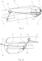
- the first surface area 105a of the first lower surface 105 is preferably, as shown in particular in Figure 4c can be clearly seen, is designed in such a way that in vertical sections through the light-conducting body 100 in the region of the lower surface 105, straight cutting curves 105a' result.
- the first surface region 105a of the first lower surface 105 forms curved intersection curves, in particular convex intersection curves, in horizontal sections. These convex intersection curves preferably follow a Petzval surface or focal surface of the projection device.
- Horizontal intersection curves are created by intersecting the respective surface with horizontal planes
- vertical intersection curves are created by intersecting the respective surface with vertical planes, which are parallel to the optical axis of the lighting device or projection device or contain the optical axis.
- the first surface area 105a forms a boundary surface of a recess 115 in the first lower boundary surface 105.
- a third surface area 105c of the first boundary surface 105 adjoins it. Due to the formation of a recess 115, this second surface area 105c is positioned such that no light from the second deflection structure 107a reaches it.
- the first surface region 105a is spaced from the second boundary surface 106, and that a further, second surface region 105b of the first boundary surface 105 is arranged between the first surface region 105a and the second boundary surface 106, which connects the first surface region 105a to the second boundary surface 106.
- the second surface region 105b is arranged and designed such that no light from the second deflection structure 107a reaches the second surface region 105b.
- a dark stripe BAN can be realized in the light image, between the light-dark boundary of the apron or low beam distribution and the lower boundary of the signlight light distribution.
- Figure 5 shows a light distribution LV in the form of a schematic pre-light distribution with a cut-off line HDG, as it can be achieved, for example, with a lighting device according to Figure 1 , but can also be generated with a lighting device 1 according to the present invention.
- Figure 5 further shows an area B in which a signlight light distribution SV is to be generated, as well as relevant measuring points for which - in this case according to the corresponding ECE regulation - defined illuminance values must be maintained.
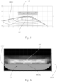
- Figure 6 shows a light distribution SV in the form of a low beam distribution with a cut-off line HDG, and above it a signlight light distribution SV.
- a dark band or stripe BAN which - as described above, in particular with reference to the Figure 4c described - can be realized by the presence of the second surface area 105b.
Landscapes
- Engineering & Computer Science (AREA)
- General Engineering & Computer Science (AREA)
- Physics & Mathematics (AREA)
- Microelectronics & Electronic Packaging (AREA)
- Optics & Photonics (AREA)
- Non-Portable Lighting Devices Or Systems Thereof (AREA)
Priority Applications (5)
| Application Number | Priority Date | Filing Date | Title |
|---|---|---|---|
| EP23211767.1A EP4560185B1 (fr) | 2023-11-23 | 2023-11-23 | Dispositif d'éclairage pour un phare de véhicule automobile et phare de véhicule automobile |
| KR1020240145579A KR20250077358A (ko) | 2023-11-23 | 2024-10-23 | 자동차 헤드라이트용 조명 장치 및 자동차 헤드라이트 |
| US18/941,872 US12492796B2 (en) | 2023-11-23 | 2024-11-08 | Illumination device for a motor vehicle headlight and motor vehicle headlight |
| JP2024198835A JP7843820B2 (ja) | 2023-11-23 | 2024-11-14 | 自動車投光器用の照射装置並びに自動車投光器 |
| CN202411686212.XA CN120027384A (zh) | 2023-11-23 | 2024-11-22 | 用于机动车前照灯的照明装置以及机动车前照灯 |
Applications Claiming Priority (1)
| Application Number | Priority Date | Filing Date | Title |
|---|---|---|---|
| EP23211767.1A EP4560185B1 (fr) | 2023-11-23 | 2023-11-23 | Dispositif d'éclairage pour un phare de véhicule automobile et phare de véhicule automobile |
Publications (2)
| Publication Number | Publication Date |
|---|---|
| EP4560185A1 true EP4560185A1 (fr) | 2025-05-28 |
| EP4560185B1 EP4560185B1 (fr) | 2026-04-08 |
Family
ID=88965196
Family Applications (1)
| Application Number | Title | Priority Date | Filing Date |
|---|---|---|---|
| EP23211767.1A Active EP4560185B1 (fr) | 2023-11-23 | 2023-11-23 | Dispositif d'éclairage pour un phare de véhicule automobile et phare de véhicule automobile |
Country Status (5)
| Country | Link |
|---|---|
| US (1) | US12492796B2 (fr) |
| EP (1) | EP4560185B1 (fr) |
| JP (1) | JP7843820B2 (fr) |
| KR (1) | KR20250077358A (fr) |
| CN (1) | CN120027384A (fr) |
Citations (5)
| Publication number | Priority date | Publication date | Assignee | Title |
|---|---|---|---|---|
| EP3290777A1 (fr) * | 2016-09-01 | 2018-03-07 | Valeo Vision | Module optique pour éclairer des points de portique |
| EP3653926A1 (fr) * | 2018-11-19 | 2020-05-20 | ZKW Group GmbH | Dispositif d'éclairage pour un phare de véhicule automobile ainsi que phare de véhicule automobile |
| EP4053447A1 (fr) * | 2019-11-01 | 2022-09-07 | Ichikoh Industries, Ltd. | Guide optique de véhicule et phare de véhicule |
| WO2023038010A1 (fr) * | 2021-09-08 | 2023-03-16 | 市光工業株式会社 | Corps de guidage de lumière de véhicule et unité d'éclairage de véhicule |
| DE112021004426T5 (de) * | 2020-08-24 | 2023-06-07 | Mitsubishi Electric Corporation | Scheinwerfermodul und scheinwerfereinrichtung |
Family Cites Families (6)
| Publication number | Priority date | Publication date | Assignee | Title |
|---|---|---|---|---|
| EP3382263B1 (fr) * | 2016-09-30 | 2020-04-08 | H.A. Automotive Systems, Inc. | Condenseur pour module de feu de véhicule à faible faisceau |
| EP3845799B1 (fr) | 2018-08-31 | 2024-10-02 | Ichikoh Industries, Ltd. | Lampe de véhicule |
| JP7151284B2 (ja) | 2018-08-31 | 2022-10-12 | 市光工業株式会社 | 車両用灯具 |
| JP7218041B2 (ja) * | 2019-05-21 | 2023-02-06 | 市光工業株式会社 | 車両用導光体及び車両用灯具ユニット |
| JP7472618B2 (ja) | 2020-04-16 | 2024-04-23 | 市光工業株式会社 | 車両用導光体及び車両用灯具ユニット |
| JP2023091257A (ja) | 2021-12-20 | 2023-06-30 | スタンレー電気株式会社 | 車両用灯具 |
-
2023
- 2023-11-23 EP EP23211767.1A patent/EP4560185B1/fr active Active
-
2024
- 2024-10-23 KR KR1020240145579A patent/KR20250077358A/ko active Pending
- 2024-11-08 US US18/941,872 patent/US12492796B2/en active Active
- 2024-11-14 JP JP2024198835A patent/JP7843820B2/ja active Active
- 2024-11-22 CN CN202411686212.XA patent/CN120027384A/zh active Pending
Patent Citations (5)
| Publication number | Priority date | Publication date | Assignee | Title |
|---|---|---|---|---|
| EP3290777A1 (fr) * | 2016-09-01 | 2018-03-07 | Valeo Vision | Module optique pour éclairer des points de portique |
| EP3653926A1 (fr) * | 2018-11-19 | 2020-05-20 | ZKW Group GmbH | Dispositif d'éclairage pour un phare de véhicule automobile ainsi que phare de véhicule automobile |
| EP4053447A1 (fr) * | 2019-11-01 | 2022-09-07 | Ichikoh Industries, Ltd. | Guide optique de véhicule et phare de véhicule |
| DE112021004426T5 (de) * | 2020-08-24 | 2023-06-07 | Mitsubishi Electric Corporation | Scheinwerfermodul und scheinwerfereinrichtung |
| WO2023038010A1 (fr) * | 2021-09-08 | 2023-03-16 | 市光工業株式会社 | Corps de guidage de lumière de véhicule et unité d'éclairage de véhicule |
Also Published As
| Publication number | Publication date |
|---|---|
| US12492796B2 (en) | 2025-12-09 |
| JP2025085077A (ja) | 2025-06-04 |
| US20250172268A1 (en) | 2025-05-29 |
| CN120027384A (zh) | 2025-05-23 |
| KR20250077358A (ko) | 2025-05-30 |
| EP4560185B1 (fr) | 2026-04-08 |
| JP7843820B2 (ja) | 2026-04-10 |
Similar Documents
| Publication | Publication Date | Title |
|---|---|---|
| EP3449178B1 (fr) | Dispositif d'illumination pour phare de véhicule avec une distribution de lumière ayant une coupure | |
| EP2799761B1 (fr) | Module d'éclairage de phare de véhicule automobile | |
| DE112016003384B4 (de) | Optische vorrichtung | |
| EP3688367B1 (fr) | Dispositif d'éclairage de véhicule à moteur comprenant des systèmes de micro-optiques comprenant des micro-optiques d'entrée subdivisées | |
| AT516836B1 (de) | Beleuchtungsvorrichtung mit Strahlenblende sowie Kraftfahrzeugscheinwerfer | |
| EP3063463B1 (fr) | Dispositif d'éclairage pour phare de véhicule automobile | |
| EP0623780B1 (fr) | Lentille de projection pour phase de véhicule | |
| DE102011089575B3 (de) | Beleuchtungseinrichtung für ein Kraftfahrzeug mit einem gestuften Lichtleiter | |
| EP3653926B1 (fr) | Dispositif d'éclairage pour un phare de véhicule automobile ainsi que phare de véhicule automobile | |
| EP3899358B1 (fr) | Dispositif d'éclairage pour un phare de véhicule automobile ainsi que phare de véhicule automobile | |
| DE69518603T2 (de) | Fahrzeugscheinwerfer | |
| DE102015222495A1 (de) | Vorsatzoptik und Vorsatzoptikanordnung mit mehreren Vorsatzoptiken | |
| EP3839324A1 (fr) | Dispositif d'éclairage pour un phare de véhicule automobile | |
| DE102012209337A1 (de) | Lichtleiter und Lichtleitervorrichtung | |
| EP4202289B1 (fr) | Système optique pour un phare de véhicule automobile | |
| DE112017006796B4 (de) | Transparenter fotoleiter mit lichtabschirmfunktion und anwendung dafür | |
| EP4560185B1 (fr) | Dispositif d'éclairage pour un phare de véhicule automobile et phare de véhicule automobile | |
| EP2951057B1 (fr) | Lampe intérieure de véhicule | |
| EP3385609B1 (fr) | Module d'éclairage pour phare de véhicule automobile | |
| DE102024112051A1 (de) | Beleuchtungsvorrichtung für Fahrzeuge | |
| EP3211470A1 (fr) | Dispositif destiné à éclairer un réticule | |
| DE102023135514A1 (de) | Anzeigevorrichtung, Virtuellbildanzeigevorrichtung und sich bewegender Körper | |
| EP4545845B1 (fr) | Dispositif d'éclairage pour un phare de véhicule automobile et phare de véhicule automobile | |
| EP3550205A1 (fr) | Conducteur de lumière pour un module lumineux de véhicule automobile | |
| DE102019127501B4 (de) | Lichtmodul, Lichtleiteranordnung, Beleuchtungseinrichtung und Kraftfahrzeug |
Legal Events
| Date | Code | Title | Description |
|---|---|---|---|
| PUAI | Public reference made under article 153(3) epc to a published international application that has entered the european phase |
Free format text: ORIGINAL CODE: 0009012 |
|
| STAA | Information on the status of an ep patent application or granted ep patent |
Free format text: STATUS: THE APPLICATION HAS BEEN PUBLISHED |
|
| AK | Designated contracting states |
Kind code of ref document: A1 Designated state(s): AL AT BE BG CH CY CZ DE DK EE ES FI FR GB GR HR HU IE IS IT LI LT LU LV MC ME MK MT NL NO PL PT RO RS SE SI SK SM TR |
|
| STAA | Information on the status of an ep patent application or granted ep patent |
Free format text: STATUS: REQUEST FOR EXAMINATION WAS MADE |
|
| 17P | Request for examination filed |
Effective date: 20251010 |
|
| GRAP | Despatch of communication of intention to grant a patent |
Free format text: ORIGINAL CODE: EPIDOSNIGR1 |
|
| STAA | Information on the status of an ep patent application or granted ep patent |
Free format text: STATUS: GRANT OF PATENT IS INTENDED |
|
| GRAS | Grant fee paid |
Free format text: ORIGINAL CODE: EPIDOSNIGR3 |
|
| GRAA | (expected) grant |
Free format text: ORIGINAL CODE: 0009210 |
|
| STAA | Information on the status of an ep patent application or granted ep patent |
Free format text: STATUS: THE PATENT HAS BEEN GRANTED |
|
| RIC1 | Information provided on ipc code assigned before grant |
Ipc: F21S 41/143 20180101AFI20260202BHEP Ipc: F21S 41/24 20180101ALI20260202BHEP Ipc: F21S 41/27 20180101ALI20260202BHEP Ipc: F21S 41/32 20180101ALI20260202BHEP Ipc: F21S 41/43 20180101ALI20260202BHEP |
|
| INTG | Intention to grant announced |
Effective date: 20260217 |
|
| AK | Designated contracting states |
Kind code of ref document: B1 Designated state(s): AL AT BE BG CH CY CZ DE DK EE ES FI FR GB GR HR HU IE IS IT LI LT LU LV MC ME MK MT NL NO PL PT RO RS SE SI SK SM TR |
|
| REG | Reference to a national code |
Ref country code: CH Ref legal event code: F10 Free format text: ST27 STATUS EVENT CODE: U-0-0-F10-F00 (AS PROVIDED BY THE NATIONAL OFFICE) Effective date: 20260408 Ref country code: GB Ref legal event code: FG4D Free format text: NOT ENGLISH |
|
| REG | Reference to a national code |
Ref country code: DE Ref legal event code: R096 Ref document number: 502023003667 Country of ref document: DE |