EP4560247A1 - Wärmetauscher - Google Patents
Wärmetauscher Download PDFInfo
- Publication number
- EP4560247A1 EP4560247A1 EP23843018.5A EP23843018A EP4560247A1 EP 4560247 A1 EP4560247 A1 EP 4560247A1 EP 23843018 A EP23843018 A EP 23843018A EP 4560247 A1 EP4560247 A1 EP 4560247A1
- Authority
- EP
- European Patent Office
- Prior art keywords
- heat exchanger
- flow path
- representing
- joining
- joining portion
- Prior art date
- Legal status (The legal status is an assumption and is not a legal conclusion. Google has not performed a legal analysis and makes no representation as to the accuracy of the status listed.)
- Pending
Links
Images





Classifications
-
- F—MECHANICAL ENGINEERING; LIGHTING; HEATING; WEAPONS; BLASTING
- F28—HEAT EXCHANGE IN GENERAL
- F28D—HEAT-EXCHANGE APPARATUS, NOT PROVIDED FOR IN ANOTHER SUBCLASS, IN WHICH THE HEAT-EXCHANGE MEDIA DO NOT COME INTO DIRECT CONTACT
- F28D9/00—Heat-exchange apparatus having stationary plate-like or laminated conduit assemblies for both heat-exchange media, the media being in contact with different sides of a conduit wall
- F28D9/0031—Heat-exchange apparatus having stationary plate-like or laminated conduit assemblies for both heat-exchange media, the media being in contact with different sides of a conduit wall the conduits for one heat-exchange medium being formed by paired plates touching each other
- F28D9/0043—Heat-exchange apparatus having stationary plate-like or laminated conduit assemblies for both heat-exchange media, the media being in contact with different sides of a conduit wall the conduits for one heat-exchange medium being formed by paired plates touching each other the plates having openings therein for circulation of at least one heat-exchange medium from one conduit to another
- F28D9/005—Heat-exchange apparatus having stationary plate-like or laminated conduit assemblies for both heat-exchange media, the media being in contact with different sides of a conduit wall the conduits for one heat-exchange medium being formed by paired plates touching each other the plates having openings therein for circulation of at least one heat-exchange medium from one conduit to another the plates having openings therein for both heat-exchange media
-
- F—MECHANICAL ENGINEERING; LIGHTING; HEATING; WEAPONS; BLASTING
- F28—HEAT EXCHANGE IN GENERAL
- F28D—HEAT-EXCHANGE APPARATUS, NOT PROVIDED FOR IN ANOTHER SUBCLASS, IN WHICH THE HEAT-EXCHANGE MEDIA DO NOT COME INTO DIRECT CONTACT
- F28D9/00—Heat-exchange apparatus having stationary plate-like or laminated conduit assemblies for both heat-exchange media, the media being in contact with different sides of a conduit wall
- F28D9/0006—Heat-exchange apparatus having stationary plate-like or laminated conduit assemblies for both heat-exchange media, the media being in contact with different sides of a conduit wall the plate-like or laminated conduits being enclosed within a pressure vessel
-
- F—MECHANICAL ENGINEERING; LIGHTING; HEATING; WEAPONS; BLASTING
- F28—HEAT EXCHANGE IN GENERAL
- F28D—HEAT-EXCHANGE APPARATUS, NOT PROVIDED FOR IN ANOTHER SUBCLASS, IN WHICH THE HEAT-EXCHANGE MEDIA DO NOT COME INTO DIRECT CONTACT
- F28D9/00—Heat-exchange apparatus having stationary plate-like or laminated conduit assemblies for both heat-exchange media, the media being in contact with different sides of a conduit wall
- F28D9/0062—Heat-exchange apparatus having stationary plate-like or laminated conduit assemblies for both heat-exchange media, the media being in contact with different sides of a conduit wall the conduits for one heat-exchange medium being formed by spaced plates with inserted elements
-
- F—MECHANICAL ENGINEERING; LIGHTING; HEATING; WEAPONS; BLASTING
- F28—HEAT EXCHANGE IN GENERAL
- F28F—DETAILS OF HEAT-EXCHANGE AND HEAT-TRANSFER APPARATUS, OF GENERAL APPLICATION
- F28F3/00—Plate-like or laminated elements; Assemblies of plate-like or laminated elements
- F28F3/08—Elements constructed for building-up into stacks, e.g. capable of being taken apart for cleaning
-
- F—MECHANICAL ENGINEERING; LIGHTING; HEATING; WEAPONS; BLASTING
- F28—HEAT EXCHANGE IN GENERAL
- F28D—HEAT-EXCHANGE APPARATUS, NOT PROVIDED FOR IN ANOTHER SUBCLASS, IN WHICH THE HEAT-EXCHANGE MEDIA DO NOT COME INTO DIRECT CONTACT
- F28D9/00—Heat-exchange apparatus having stationary plate-like or laminated conduit assemblies for both heat-exchange media, the media being in contact with different sides of a conduit wall
- F28D9/0081—Heat-exchange apparatus having stationary plate-like or laminated conduit assemblies for both heat-exchange media, the media being in contact with different sides of a conduit wall the conduits for one heat-exchange medium being formed by a single plate-like element ; the conduits for one heat-exchange medium being integrated in one single plate-like element
-
- F—MECHANICAL ENGINEERING; LIGHTING; HEATING; WEAPONS; BLASTING
- F28—HEAT EXCHANGE IN GENERAL
- F28F—DETAILS OF HEAT-EXCHANGE AND HEAT-TRANSFER APPARATUS, OF GENERAL APPLICATION
- F28F2215/00—Fins
- F28F2215/02—Arrangements of fins common to different heat exchange sections, the fins being in contact with different heat exchange media
-
- F—MECHANICAL ENGINEERING; LIGHTING; HEATING; WEAPONS; BLASTING
- F28—HEAT EXCHANGE IN GENERAL
- F28F—DETAILS OF HEAT-EXCHANGE AND HEAT-TRANSFER APPARATUS, OF GENERAL APPLICATION
- F28F2265/00—Safety or protection arrangements; Arrangements for preventing malfunction
- F28F2265/14—Safety or protection arrangements; Arrangements for preventing malfunction for preventing damage by freezing, e.g. for accommodating volume expansion
-
- F—MECHANICAL ENGINEERING; LIGHTING; HEATING; WEAPONS; BLASTING
- F28—HEAT EXCHANGE IN GENERAL
- F28F—DETAILS OF HEAT-EXCHANGE AND HEAT-TRANSFER APPARATUS, OF GENERAL APPLICATION
- F28F2265/00—Safety or protection arrangements; Arrangements for preventing malfunction
- F28F2265/26—Safety or protection arrangements; Arrangements for preventing malfunction for allowing differential expansion between elements
Definitions
- the present disclosure relates to a heat exchanger.
- PTL 1 Japanese Unexamined Patent Application Publication No. 10-132476 discloses, as a fifth embodiment, a heat exchanger including heat transfer plates capable of absorbing stress by elastic deformation to suppress breakage even when the volume expansion of the frozen water occurs.
- the present disclosure provides a heat exchanger that suppresses leakage of a refrigerant when water freezes and expands in volume.
- a heat exchanger of a first aspect is a heat exchanger that causes heat exchange between water and a refrigerant, and includes a first flow path through which the water flows and a second flow path through which the refrigerant flows. Any one of members forming the first flow path other than a partition wall partitioning the first flow path and the second flow path or any one of joining portions where members forming the first flow path are joined to each other functions as a fragile portion with a lower strength than the other members forming the first flow path.
- a heat exchanger of a second aspect is the heat exchanger of the first aspect, wherein the first flow path is formed using two partition walls, inner fins, and separation members.
- the inner fins are stacked between the two partition walls and each have a corrugated cross section.
- the separation members are disposed at end edges of the two partition walls and each separate the two partition walls from each other.
- a heat exchanger of a third aspect is the heat exchanger of the second aspect, wherein the fragile portion is the inner fins.
- the inner fins forming the first flow path breaks before other portions.
- the leakage of the refrigerant due to the breakage of the members or the joining portions forming the second flow path is suppressed.
- a heat exchanger of a fourth aspect is the heat exchanger of the third aspect, wherein the following relationship is satisfied with tw representing a thickness of the inner fin, Lw representing an interval between top portions of the inner fin in contact with the same partition wall, tR representing a thickness of the partition wall, and hw representing a height of the inner fin in a stacking direction: tw / Lw ⁇ tR / hw .
- a heat exchanger of a fifth aspect is the heat exchanger of the second aspect, wherein the fragile portion is the separation members.
- the separation members forming the first flow path break before the other portions.
- the leakage of the refrigerant due to the breakage of the members or the joining portions forming the second flow path is suppressed.
- a heat exchanger of a sixth aspect is the heat exchanger of the fifth aspect, wherein the following relationship is satisfied with Lsp representing a width of the separation member in plan view, tw representing a thickness of the inner fin, Lw representing an interval between top portions of the inner fin in contact with the same partition wall, tR representing a thickness of the partition wall, and hw representing a height of the inner fin in a stacking direction: Lsp + tw / Lw ⁇ tR / hw .
- a heat exchanger of a seventh aspect is the heat exchanger of the first aspect, wherein the first flow path is formed using two partition walls, inner fins, and separation members.
- the inner fins are stacked between the two partition walls and each have a corrugated cross section.
- the separation members are disposed at end edges of the two partition walls and each separate the two partition walls from each other.
- the heat exchanger includes a first joining portion and a second joining portion.
- the first joining portion is a portion where the partition wall and top portions of the inner fin are joined.
- the second joining portion is a portion where the partition wall and the separation member are joined.
- a heat exchanger of an eighth aspect is the heat exchanger of the seventh aspect, wherein the fragile portion is the first joining portion.
- the first joining portion where members forming the first flow path are joined to each other breaks before the other portions.
- the leakage of the refrigerant due to the breakage of the members or the joining portions forming the second flow path is suppressed.
- a heat exchanger of a ninth aspect is the heat exchanger of the eighth aspect, wherein joining in the first joining portion is joined by brazing.
- the following relationship is satisfied with bw1 representing a width of the first joining portion, Lw representing an interval between the top portions of the inner fin in contact with the same partition wall, tR representing a thickness of the partition wall, and hW representing a height of the inner fin in a stacking direction: 0.35 ⁇ bw 1 / 2 ⁇ Lw ⁇ tR / hw .
- a heat exchanger of a tenth aspect is the heat exchanger of the eighth aspect, wherein joining in the first joining portion is implemented by diffusion joining.
- the following relationship is satisfied with bw1 representing a width of the first joining portion, Lw representing an interval between the top portions of the inner fin in contact with the same partition wall, tR representing a thickness of the partition wall, and hW representing a height of the inner fin in a stacking direction: bw 1 / 2 ⁇ Lw ⁇ tR / hw .
- a heat exchanger of an eleventh aspect is the heat exchanger of the seventh aspect, wherein the fragile portion is the second joining portion.
- the second joining portion where members forming the first flow path are joined to each other breaks before the other portions.
- the leakage of the refrigerant due to the breakage of the members or the joining portions forming the second flow path is suppressed.
- a heat exchanger of a twelfth aspect is the heat exchanger of the eleventh aspect, wherein joining in the second joining portion is joined by brazing.
- the following relationship is satisfied with bsp2 representing a width of the second joining portion, bw1 representing a width of the first joining portion, Lw representing an interval between the top portions of the inner fin in contact with the same partition wall, tR representing a thickness of the partition wall, and hW representing a height of the inner fin in a stacking direction: 0.35 ⁇ (2 ⁇ bsp2 + bw1)/Lw ⁇ 2 ⁇ tR/hw. 0.35 ⁇ 2 ⁇ bsp 2 + bw 1 / Lw ⁇ 2 ⁇ tR / hw .
- a heat exchanger of a thirteenth aspect is the heat exchanger of the eleventh aspect, wherein joining in the second joining portion is implemented by diffusion joining.
- the following relationship is satisfied with bsp2 representing a width of the second joining portion, bw1 representing a width of the first joining portion, Lw representing an interval between the top portions of the inner fin in contact with the same partition wall, tR representing a thickness of the partition wall, and hW representing a height of the inner fin in a stacking direction: 2 ⁇ bsp 2 + bw 1 / Lw ⁇ 2 ⁇ tR / hw .
- a heat exchanger of a fourteenth aspect is the heat exchanger of the first aspect, wherein the first flow path is formed using two heat transfer plates.
- the heat exchanger includes a third joining portion and a fourth joining portion.
- the two heat transfer plates are stacked on each other and each have a corrugated cross section.
- the third joining portion is a portion where top portions of the two heat transfer plates are joined.
- the fourth joining portion is a portion where end edges of the two heat transfer plates are joined.
- a heat exchanger of a fifteenth aspect is the heat exchanger of the fourteenth aspect, wherein the fragile portion is the third joining portion.
- the third joining portion 210d where members forming the first flow path are joined to each other breaks before the other portions.
- the leakage of the refrigerant due to the breakage of the members or the joining portions forming the second flow path is suppressed.
- a heat exchanger of a sixteenth aspect is the heat exchanger of the fifteenth aspect, wherein joining in the third joining portion is joined by brazing.
- the following relationship is satisfied with bw3 presenting a width of the third joining portion as viewed along a normal direction and t representing a thickness of the heat transfer plate: 0.35 ⁇ bw 3 ⁇ 2 ⁇ t .
- a heat exchanger of a seventeenth aspect is the heat exchanger of the fifteenth aspect, wherein joining in the third joining portion is implemented by diffusion joining.
- the following relationship is satisfied with bw3 presenting a width of the third joining portion as viewed along a normal direction and t representing a thickness of the heat transfer plate: bw 3 ⁇ 2 ⁇ t .
- a heat exchanger of an eighteenth aspect is the heat exchanger of the fourteenth aspect, wherein the fragile portion is the fourth joining portion.
- a heat exchanger of a nineteenth aspect is the heat exchanger of the eighteenth aspect, wherein joining in the fourth joining portion is joined by brazing.
- the following relationship is satisfied with bsp4 representing a width of the fourth joining portion as viewed along a normal direction,bw3 presenting a width of the third joining portion as viewed along the normal direction, and t representing a thickness of the heat transfer plate: 0.35 ⁇ bsp 4 + bw 3 / 2 ⁇ 2 ⁇ t
- a heat exchanger of a twentieth aspect is the heat exchanger of the eighteenth aspect, wherein joining in the fourth joining portion is implemented by diffusion joining.
- the following relationship is satisfied with bsp4 representing a width of the fourth joining portion as viewed along a normal direction, bw3 presenting a width of the third joining portion as viewed along the normal direction, and t representing a thickness of the heat transfer plate: bsp 4 + bw 3 / 2 ⁇ 2 ⁇ t .
- a heat exchanger of a twenty-first aspect is the heat exchanger of the first aspect, including a first heat transfer plate and a second heat transfer plate.
- the first heat transfer plate has the first flow path formed therein.
- the second heat transfer plate has the second flow path formed therein.
- the fragile portion is the first heat transfer plate.
- the first heat transfer plate forming the first flow path breaks before the other portions.
- the leakage of the refrigerant due to the breakage of the second heat transfer plate forming the second flow path is suppressed.
- a heat exchanger of a twenty-second aspect is the heat exchanger of the twenty-first aspect, wherein the first heat transfer plate is formed by stacking two plate-shaped members in which grooves forming the first flow path are formed.
- the fragile portion is a portion where the two plate-shaped members are joined.
- the portion where the two plate-shaped members forming the first heat transfer plate are joined breaks before the other portions.
- the leakage of the refrigerant due to the breakage of the second heat transfer plate forming the second flow path is suppressed.
- a heat exchanger of a twenty-third aspect is the heat exchanger of any of the first to twenty-second aspects, wherein the refrigerant is flammable or toxic.
- the leakage of the refrigerant due to the breakage of the members or the joining portions forming the second flow path 121 can be suppressed.
- a heat exchanger of a twenty-fourth aspect is the heat exchanger of any of the first to twenty-third aspects, wherein the fragile portion is formed with such a strength that the fragile portion breaks when the water freezes.
- the refrigerant cycle apparatus 1 heats or cools water supplied from the outside of the refrigerant cycle apparatus 1, such as city water (tap water), and supplies the water.
- the refrigerant cycle apparatus 1 includes a water intake unit 1a, a water supply unit 1b, the heat exchanger 100, a refrigerant circuit 10, a water circuit 20, a water supply unit 30, and a control unit 40.
- the water supply unit 30 is installed indoors, and the water circuit 20 and the refrigerant circuit 10 are installed outdoors.
- a refrigerant circulates in the refrigerant circuit 10, and water circulates in the water circuit 20.
- the water intake unit 1a takes in water supplied from the outside into the refrigerant cycle apparatus 1.
- the water supply unit 1b supplies to the outside, water heated or cooled in the refrigerant cycle apparatus 1.
- the heat exchanger 100 causes heat exchange between the refrigerant circulating in the refrigerant circuit 10 and the water circulating in the water circuit 20.
- the heat exchanger 100 includes first flow pipes 170a and 170b, second flow pipes 180a and 180b, a first flow path 111, and a second flow path 121.
- the first flow path 111 is a flow path through which water flows.
- the first flow path 111 is provided between the first flow pipe 170a and the first flow pipe 170b.
- the second flow path 121 is a flow path through which the refrigerant flows.
- the second flow path 121 is formed between the second flow pipe 180a and the second flow pipe 180b. A detailed structure of the heat exchanger 100 will be described below.
- the refrigerant circuit 10 the refrigerant is heated or cooled.
- the refrigerant circuit 10 includes a compressor 11, a four-way switching valve 12, a heat source heat exchanger 13, an expansion valve 14, and the second flow path 121 of the heat exchanger 100.
- the compressor 11, the four-way switching valve 12, the heat source heat exchanger 13, the expansion valve 14, and the second flow path 121 of the heat exchanger 100 are connected by pipes, and the refrigerant circulates therein.
- the refrigerant is propane.
- the compressor 11 takes in a low-pressure refrigerant in the refrigerant circuit 10 through an intake portion 11a, compresses the refrigerant, and discharges the refrigerant as a high-pressure refrigerant through a discharge portion 11b.
- the four-way switching valve 12 has a first port P1, a second port P2, a third port P3, and a fourth port P4.
- the four-way switching valve 12 is switched between a first state and a second state different from each other in a communication state of the first port P1, the second port P2, the third port P3, and the fourth port P4, based on an instruction from the control unit 40.
- the first state the first port P1 and the second port P2 communicate with each other, and the third port P3 and the fourth port P4 communicate with each other.
- the first port P1 and the fourth port P4 communicate with each other, and the second port P2 and the third port P3 communicate with each other.
- the first port P1 is connected to the discharge portion 11b of the compressor 11.
- the second port P2 is connected to the second flow pipe 180a of the heat exchanger 100.
- the third port P3 is connected to the intake portion 11a of the compressor 11.
- the fourth port P4 is connected to one end of the heat source heat exchanger 13.
- the heat source heat exchanger 13 causes heat exchange between the refrigerant circulating in the refrigerant circuit 10 and a heat source (for example, outdoor air).
- a heat source for example, outdoor air
- the expansion valve 14 functions as a pressure reducing device that adjusts the flow rate of the refrigerant circulating in the refrigerant circuit 10 and reduces the pressure of the refrigerant.
- One end of the expansion valve 14 is connected to the other end of the heat source heat exchanger 13.
- the other end of the expansion valve 14 is connected to the second flow pipe 180b of the heat exchanger 100.
- the water circuit 20 includes the first flow path 111 of the heat exchanger 100, a water circulation pump 21, a flow rate adjustment valve 22, and a utilization heat exchanger 23.
- the first flow path 111 of the heat exchanger 100, the water circulation pump 21, the flow rate adjustment valve 22, and the utilization heat exchanger 23 are connected to each other by pipes, and water circulates therein.
- the water circulation pump 21 makes the water circulate inside the water circuit 20.
- the water circulation pump 21 takes in water in the water circuit 20 through an intake portion 21a and discharges the water through a discharge portion 21b.
- the intake portion 21a is connected to the first flow pipe 170a of the heat exchanger 100.
- the discharge portion 21b is connected to one end of the flow rate adjustment valve 22.
- the flow rate adjustment valve 22 adjusts the flow rate of water circulating in the water circuit 20.
- the utilization heat exchanger 23 causes heat exchange between the water circulating in the water circuit 20 and water stored in a water storage tank 31 (described below) of the water supply unit 30.
- the utilization heat exchanger 23 is disposed inside the water storage tank 31 so that water passing therethrough can exchange heat with the water stored in the water storage tank 31.
- One end of the utilization heat exchanger 23 is connected to the other end of the flow rate adjustment valve 22.
- the other end of the utilization heat exchanger 23 is connected to the first flow pipe 170b of the heat exchanger 100.
- the water circuit 20 may further include a heat exchanger for heating or cooling indoor air using the circulating water.
- the water supply unit 30 causes heat exchange between the water supplied from the outside of the refrigerant cycle apparatus 1 and the water circulating in the water circuit 20, and then supplies the water to the outside of the refrigerant cycle apparatus 1.
- the water supply unit 30 includes the water storage tank 31, a water supply pump 32, and a mixing valve 33.
- the water storage tank 31, the water supply pump 32, and the mixing valve 33 are connected by a pipe.
- the water storage tank 31 stores the water supplied from the outside.
- the stored water exchanges heat with the water passing through the utilization heat exchanger 23.
- the water storage tank 31 takes in water supplied from the outside through a water intake portion 31a and stores the water.
- the stored water exchanges heat with water passing through the utilization heat exchanger 23, and is discharged from a water discharge portion 81b.
- the water intake portion 31a is connected to the water intake unit 1a to which water is supplied from the outside.
- the water supply pump 32 takes in water stored in the water storage tank 31 and supplies the water to the mixing valve 33.
- the water supply pump 32 takes in water inside the water storage tank 31 through an intake portion 32a, and discharges the water through a discharge portion 32b.
- the intake portion 32a is connected to a water discharge portion 31b.
- the discharge portion 32b is connected to a second port 33b (described below) of the mixing valve 33.
- the mixing valve 33 mixes water supplied from the outside and water stored in the water storage tank 31.
- the mixing valve 33 has a first port 33a, the second port 33b, and a third port 33c.
- the first port 33a is connected to the water intake unit 1a to which water is supplied from the outside.
- the second port 33b is connected to the discharge portion 32b of the water supply pump 32.
- the third port 33c is connected to the water supply unit 1b that communicates with the outside of the refrigerant cycle apparatus 1.
- the control unit 40 controls the compressor 11, the four-way switching valve 12, the expansion valve 14, the water circulation pump 21, the flow rate adjustment valve 22, the water supply pump 32, and the mixing valve 33.
- the control unit 40 is electrically connected to the compressor 11, the four-way switching valve 12, the expansion valve 14, the water circulation pump 21, the flow rate adjustment valve 22, the water supply pump 32, and the mixing valve 33 in such a manner that a control signal can be transmitted and received therebetween.
- the refrigerant cycle apparatus 1 performs a heating operation, a cooling operation, and a defrosting operation.
- the heating operation is an operation in which the refrigerant cycle apparatus 1 heats water that is supplied from the outside to the water intake unit 1a and supplies the heated water through the water supply unit 1b.
- the control unit 40 sets the four-way switching valve 12 to the first state, drives the compressor 11, the water circulation pump 21, and the water supply pump 32, and controls the opening degrees of the expansion valve 14, the flow rate adjustment valve 22, and the mixing valve 33.
- the compressor 11 takes in a low-pressure gas-phase refrigerant in the refrigerant circuit 10 through the intake portion 11a, and discharges the refrigerant as a high-pressure gas-phase refrigerant through the discharge portion 11b.
- the high-pressure gas-phase refrigerant passes through the four-way switching valve 12 in the order of the first port P1 and the second port P2, and reaches the second flow path 121 of the heat exchanger 100.
- the high-pressure gas-phase refrigerant is condensed into a high-pressure liquid-phase refrigerant. In this process, the refrigerant releases heat to the water passing through the first flow path 111.
- the high-pressure liquid-phase refrigerant reaches the expansion valve 14.
- the expansion valve 14 set to an appropriate opening degree decompresses the high-pressure liquid-phase refrigerant into a low-pressure gas-liquid two phase refrigerant.
- the low-pressure gas-liquid two phase refrigerant evaporates in the heat source heat exchanger 13 to become a low-pressure gas-phase refrigerant. In this process, the refrigerant absorbs heat from the heat source (outside air).
- the low-pressure gas-phase refrigerant passes through the four-way switching valve 12 in the order of the fourth port P4 and the third port P3, and is then taken into the compressor 11 through the intake portion 11a.
- the water circulation pump 21 takes in water circulating in the water circuit 20 through the intake portion 21a and discharges the water through the discharge portion 21b.
- the discharged water reaches the utilization heat exchanger 23 through the flow rate adjustment valve 22.
- the water that has reached the utilization heat exchanger 23 releases heat to the water stored in the water storage tank 31 in the utilization heat exchanger 23.
- the water that has reached the utilization heat exchanger 23 heats the water stored in the water storage tank 31 in the utilization heat exchanger 23.
- the water that has released heat in the utilization heat exchanger 23 reaches the first flow path 111 of the heat exchanger 100.
- the water that has reached the first flow path 111 of the heat exchanger 100 absorbs heat from the refrigerant passing through the second flow path 121.
- the water that has absorbed heat is taken into the water circulation pump 21 through the intake portion 21a.
- the water stored in the water storage tank 31 is heated by absorbing heat from the water passing through the utilization heat exchanger 23.
- the water supply pump 32 takes in the water heated in the water storage tank 31 through the intake portion 32a.
- the water taken into the water supply pump 32 is discharged through the discharge portion 32b to the mixing valve 33.
- the water discharged from the water supply pump 32 passes through the second port 33b and is then mixed with the water from the outside that has reached the first port 33a through the water intake unit 1a.
- the mixed water from the mixing valve 33 passes through the third port 33c and is then supplied to the outside of the refrigerant cycle apparatus 1 from the water supply unit 1b.
- the cooling operation is an operation in which the refrigerant cycle apparatus 1 cools water that is supplied from the outside to the water intake unit 1a and supplies the cooled water from the water supply unit 1b.
- the control unit 40 sets the four-way switching valve 12 to the second state, drives the compressor 11, the water circulation pump 21, and the water supply pump 32, and controls the opening degrees of the expansion valve 14, the flow rate adjustment valve 22, and the mixing valve 33.
- the compressor 11 takes in a low-pressure gas-phase refrigerant in the refrigerant circuit 10 through the intake portion 11a, and discharges the refrigerant as a high-pressure gas-phase refrigerant through the discharge portion 11b.
- the high-pressure gas-phase refrigerant passes through the four-way switching valve 12 in the order of the first port P1 and the fourth port P4, and reaches the heat source heat exchanger 13.
- the heat source heat exchanger 13 the high-pressure gas-phase refrigerant is condensed into a high-pressure liquid-phase refrigerant. In this process, the refrigerant releases heat to a heat source (outside air).
- the high-pressure liquid-phase refrigerant reaches the expansion valve 14.
- the expansion valve 14 set to an appropriate opening degree decompresses the high-pressure liquid-phase refrigerant into a low-pressure gas-liquid two phase refrigerant.
- the low-pressure gas-liquid two phase refrigerant evaporates in the second flow path 121 of the heat exchanger 100 to become a low-pressure gas-phase refrigerant.
- the refrigerant absorbs heat from the water passing through the first flow path 111.
- the low-pressure gas-phase refrigerant passes through the four-way switching valve 12 in the order of the second port P2 and the third port P3, and is then taken into the compressor 11 through the intake portion 11a.
- the water circulation pump 21 takes in water circulating in the water circuit 20 through the intake portion 21a and discharges the water through the discharge portion 21b.
- the discharged water reaches the utilization heat exchanger 23 through the flow rate adjustment valve 22.
- the water that has reached the utilization heat exchanger 23 absorbs heat from the water stored in the water storage tank 31 in the utilization heat exchanger 23. In other words, the water that has reached the utilization heat exchanger 23 cools the water stored in the water storage tank 31 in the utilization heat exchanger 23.
- the water that has absorbed heat in the utilization heat exchanger 23 reaches the first flow path 111 of the heat exchanger 100.
- the water that has reached the first flow path 111 of the heat exchanger 100 releases heat to the refrigerant passing through the second flow path 121.
- the water that has released heat is taken into the water circulation pump 21 through the intake portion 21a.
- the water stored in the water storage tank 31 is cooled by releasing heat to the water passing through the utilization heat exchanger 23.
- the water supply pump 32 takes in water cooled in the water storage tank 31 through the intake portion 32a.
- the water taken into the water supply pump 32 is discharged through the discharge portion 32b to the mixing valve 33.
- the water discharged from the water supply pump 32 passes through the second port 33b and is then mixed with the water from the outside that has reached the first port 33a through the water intake unit 1a.
- the mixed water from the mixing valve 33 passes through the third port 33c and is then supplied to the outside of the refrigerant cycle apparatus 1 from the water supply unit 1b.
- the defrosting operation is an operation in which frost that has adhered to the surface of the heat source heat exchanger 13 during the heating operation is melted and removed by the heat of the refrigerant condensed in the heat source heat exchanger 13.
- the operation of each part of the refrigerant cycle apparatus 1 in the defrosting operation is the same as that in the cooling operation described above. Therefore, a detailed description of the defrosting operation will be omitted.
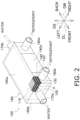
- the heat exchanger 100 is a heat exchanger including a plurality of first inner fins 110, a plurality of second inner fins 120, a plurality of partition walls 130, a first separation member 140, a second separation member 150, a casing 160, the first flow pipe 170a, the first flow pipe 170b, the second flow pipe 180a, and the second flow pipe 180b.
- the first flow path 111 through which water flows and the second flow path 121 through which a refrigerant flows are formed inside the heat exchanger 100.
- the heat exchanger 100 has a fragile portion 190 that prevents the refrigerant flowing through the second flow path 121 from flowing into the first flow path 111 when water freezes.
- the first inner fins 110, the second inner fins 120, and the partition walls 130 are plate-shaped members made of metal and formed in the same rectangular outer shape.
- the outer shapes of the first inner fins 110, the second inner fins 120, and the partition walls 130 are formed in a rectangular shape elongated in a first direction.
- the first inner fins 110 and the second inner fins 120 are alternately stacked with the partition wall 130 interposed therebetween and are accommodated in the casing 160.
- the number of each of the first inner fins 110 and the second inner fins 120 is not limited, and is appropriately set according to the required performance.
- the first direction may be referred to as a longitudinal direction DL.
- a direction orthogonal to the first direction may be referred to as a width direction DW.
- a direction in which the first inner fins 110, the partition wall 130, and the second inner fins 120 are stacked may be referred to as a stacking direction DS.
- the longitudinal direction DL, the width direction DW, and the stacking direction DS correspond to the directions indicated by the arrows in the drawing.
- the back, front, left, and right directions used in the following description correspond to the directions indicated by the arrows in Figs. 2 to 5 .
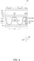
- the first inner fin 110 is a corrugated fin having a corrugated cross section.
- the corrugated shape of the first inner fin 110 is formed such that a top portion 110t of the corrugated shape extends along the longitudinal direction DL in plan view.
- the first inner fin 110 forms the first flow path 111 together with the partition walls 130 adjacently stacked and the first separation member 140 separating the partition walls 130 from each other.
- the first inner fin 110 is formed by, for example, but not limited to, pressing.
- corrugated is not limited to a shape in which semicircular recesses and protrusions are periodically arranged as illustrated in Fig. 6 , and may be a periodically changing shape such as a sine wave, a rectangular wave, or a triangular wave shape. The same applies to the second inner fin 120.
- the second inner fin 120 is a corrugated fin having a corrugated cross section.
- the corrugated shape of the second inner fin 120 is formed such that a top portion 120t of the corrugated shape extends along the width direction DW in plan view.
- the second inner fin 120 forms the second flow path 121 together with the partition walls 130 adjacently stacked.
- the second inner fin 120 is formed by, for example, but not limited to, pressing.
- the partition wall 130 is a flat plate that separates the first inner fin 110 and the second inner fin 120 in the stacking direction DS.
- the first separation member 140 is a member that separates two partition walls 130 from each other in order to dispose the first inner fin 110 between the partition walls 130 adjacent to each other in the stacking direction DS.
- the first separation member 140 is a strip-shaped member extending along the longitudinal direction DL.
- the first separation members 140 are disposed along both end edges of the partition wall 130 in the width direction DW.
- the height of the first separation member 140 in the stacking direction DS is set to be the same as the height of the first inner fin 110 in the stacking direction DS.
- the first inner fin 110 is disposed between the first separation members 140 disposed along both end edges of the partition wall 130 in the width direction DW.
- the second separation member 150 is a member that separates two partition walls 130 from each other in order to dispose the second inner fin 120 between the partition walls 130 adjacent to each other in the stacking direction DS.
- the second separation member 150 is a strip-shaped member extending along the width direction DW.
- the second separation members 150 are disposed along both end edges of the partition wall 130 in the longitudinal direction DL.
- the height of the second separation member 150 in the stacking direction DS is set to be the same as the height of the second inner fin 120 in the stacking direction DS.
- the first inner fin 110 is disposed between the second separation members 150 disposed along both end edges of the partition wall 130 in the longitudinal direction DL.
- the casing 160 is a substantially rectangular parallelepiped member that accommodates the first inner fins 110, the second inner fins 120, the partition walls 130, the first separation members 140, and the second separation members 150.
- the casing 160 has two main surfaces 160a orthogonal to the stacking direction DS, two first side surfaces 160b, and two second side surfaces 160c.
- the main surfaces 140a are surfaces orthogonal to the stacking direction DS.
- the first side surfaces 160b are surfaces orthogonal to the longitudinal direction DL.
- the second side surfaces 160c are surfaces orthogonal to the width direction DW.
- a first header 141, a second header 142, a third header 143, a fourth header 144, and a fifth header 145 are formed inside the casing 160.
- the first header 141 is a space in which water flowing into the casing 160 is distributed to a plurality of first flow paths 111.
- the first header 141 is formed along the first side surface 160b on the back side.
- the second header 142 is a space in which the water that has passed through the first flow paths 111 merges.
- the second header 142 is formed along the first side surface 160b on the front side.
- the third header 143 is a space in which the refrigerant flowing into the casing 160 is distributed to a plurality of second flow paths 121.
- the third header 143 is formed along the back side of the second side surface 160c on the right side.
- the fourth header 144 is a space in which the refrigerant that has passed through the second flow paths 121 merges.
- the fourth header 144 is formed along the front side of the second side surface 160c on the right side.
- the fifth header 145 is a space in which the refrigerant that has passed through the second flow paths 121 is merged, and then the flow direction is changed, and the flow of the refrigerant is branched again to the second flow paths 121.
- the fifth header 145 includes a fifth header 145a, a fifth header 145b, and a fifth header 145c. As illustrated in Fig. 5 , the fifth header 145a is formed along the back side of the second side surface 160c on the left side.
- the fifth header 145b is formed along the second side surface 160c on the right side between the fourth header 144 and the fifth header 145.
- the fifth header 145c is formed along the front side of the second side surface 160c on the left side.
- the first flow pipe 170a is a pipe for making water flow through the first flow paths 111.
- the first flow pipe 170a is provided, in the casing 160, through the first side surface 160b on the front side and communicates with the first header 141.
- the first flow pipe 170b is a pipe for making water flow through the first flow paths 111.
- the first flow pipe 170b is provided, in the casing 160, through the first side surface 160b on the back side and communicates with the second header 142.
- the second flow pipe 180a is a pipe for making the refrigerant flow through the second flow paths 121.
- the second flow pipe 180a is provided, in the casing 160, through the second side surface 160c on the right side and communicates with the third header 143.
- the second flow pipe 180b is a pipe for making water flow through the second flow paths 121.
- the second flow pipe 180b is provided, in the casing 160, through the second side surface 160c on the right side and communicates with the fourth header 144.
- the first inner fin 110 is accommodated in a space surrounded by two partition walls 130 adjacent to each other in the stacking direction DS and two first separation members 140 disposed between these partition walls 130, whereby the plurality of first flow paths 111 arranged in the width direction DW are formed.
- the first flow path 111 is a space surrounded by the first inner fin 110 and the partition wall 130 and extending in the longitudinal direction DL, and a space surrounded by the first inner fin 110, the partition wall 130, and the first separation member 140 and extending in the longitudinal direction DL.
- the first inner fin 110, the partition wall 130, and the first separation member 140 are joined by brazing. More specifically, the first inner fin 110 has the top portion 110t of the corrugated shape joined to the partition wall 130 by brazing. A surface of the first separation member 140 orthogonal to the stacking direction DS is joined to the partition wall 130 by brazing.
- a portion where the top portion 110t and the partition wall 130 are joined is referred to as a first joining portion 110c
- a portion where the partition wall 130 and the first separation member 140 are joined is referred to as a second joining portion 140c.
- the first joining portion 110c and the second joining portion 140c are examples of joining portions.
- the second inner fin 120 is accommodated in a space surrounded by two partition walls 130 adjacent to each other in the stacking direction DS and two second separation members 150 disposed between these partition walls 130, whereby the plurality of second flow paths 121 arranged in the longitudinal direction DL are formed.
- the second flow path 121 is a space surrounded by the second inner fin 120 and the partition wall 130 and extending in the width direction DW, and a space surrounded by the second inner fin 120, the partition wall 130, and the second separation member 150 and extending in the width direction DW.
- the plurality of first inner fins 110 and the plurality of second inner fins 120 are alternately stacked with the partition wall 130 interposed therebetween, whereby the plurality of first flow paths 111 arranged in the width direction DW and the plurality of second flow paths 121 arranged in the longitudinal direction DL are stacked in a parallel cross form in the stacking direction DS.
- the heat exchanger 100 has the fragile portion 190 that has lower strength than other portions and breaks when the water freezes and expands in volume.
- the fragile portion 190 is a member that forms the first flow path 111 and is any member other than the partition wall 130 separating the first flow path 111 and the second flow path 121.
- the first inner fin 110 and the first separation member 140 function as the fragile portion 190.
- it is preferable that the first inner fin 110 and the first separation member 140 are formed such that the first inner fin 110 breaks first and then the first separation member 140 breaks when the volume expansion of the water reaches or exceeds a certain level.
- the sizes of the respective parts forming the first flow path 111 satisfy the relationship described in (Formula 1) below.
- tw represents the thickness of the first inner fins 110
- Lw represents the interval of the top portions 110t in contact with the same partition wall 130
- tR represents the thickness of the partition wall 130
- hw represents the height of the first inner fins in the stacking direction DS.
- tw is, for example, 0.15 mm.
- Lw is 2 mm
- tR is 0.15 mm
- Hw is 1 mm.
- the sizes of the portions forming the first flow path 111 satisfy the relationship described in (Formula 2) below.
- Lsp represents the width of the first separation members 140 in plan view. Lsp + tw / Lw ⁇ tR / hw ...
- Lsp is 0.1 mm.
- the water introduced from the first flow pipe 170a of the heat exchanger 100 passes through the first header 141 and flows into the first flow path 111.
- the water that has flowed into the first flow path 111 flows through the first flow path 111 toward the back side along the longitudinal direction DL.
- the water that has reached the back side passes through the second header 142 and is led out from the first flow pipe 170b.
- the water introduced from the first flow pipe 170b of the heat exchanger 100 passes through the second header 142 and flows into the first flow path 111.
- the water that has flowed into the first flow path 111 flows through the first flow path 111 toward the front side along the longitudinal direction DL.
- the water that has reached the front side passes through the first header 141 and is led out from the first flow pipe 170a. In either case, the water flowing through the first flow path 111 exchanges heat with the refrigerant in the adjacent second flow path 121 via the partition wall 130.
- the refrigerant introduced from the second flow pipe 180a of the heat exchanger 100 passes through the third header 143 and flows into the second flow path 121.
- the refrigerant that has flowed into the second flow path 121 flows through the second flow path 121 from the right side toward the left side along the width direction DW.
- the refrigerant that has reached the left side merges in the fifth header 145a, then flows toward the front side along the longitudinal direction DL, and is again divided into the plurality of second flow paths 121.
- the refrigerant that has flowed into the second flow path 121 from the fifth header 145a flows through the second flow path 121 from the left side toward the right side along the width direction DW.
- the refrigerant flows through the fifth header 145b, the second flow path 121, the fifth header 145c, and the second flow path 121 in this order while repeatedly branching and merging, then passes through the fourth header 144, and is led out from the second flow pipe 180b.
- the refrigerant introduced from the second flow pipe 180b of the heat exchanger 100 passes through the fourth header 144 and flows into the second flow path 121.
- the refrigerant that has flowed into the second flow path 121 flows through the second flow path 121 from the right side toward the left side along the width direction DW.
- the refrigerant that has reached the left side merges in the fifth header 145c, then flows toward the back side and the front side along the longitudinal direction DL, and is again divided into the plurality of second flow paths 121.
- the refrigerant that has flowed into the second flow path 121 from the fifth header 145c flows through the second flow path 121 from the left side toward the right side along the width direction DW.
- the refrigerant flows through the fifth header 145b, the second flow path 121, the fifth header 145a, and the second flow path 121 in this order while repeatedly branching and merging, then passes through the third header 143, and is led out from the second flow pipe 180a.
- the water flowing through the second flow path 121 is condensed (during the heating operation) or evaporated (during the cooling operation and the defrosting operation) by exchanging heat with the water in the adjacent first flow path 111 via the partition wall 130.
- the heat exchanger 100 is a heat exchanger that causes heat exchange between water and a refrigerant, and includes the first flow path 111 through which water flows and the second flow path 121 through which the refrigerant flows. Any of the members forming the first flow path 111 other than the partition wall 130 separating the first flow path 111 and the second flow path 121 functions as the fragile portion 190 having a lower strength than the other members forming the first flow path 111.
- any of the members forming the first flow path 111 functioning as the fragile portion 190 other than the partition wall 130 separating the first flow path 111 and the second flow path 121 breaks before the other portions. Therefore, according to the heat exchanger 100, when water freezes and expands in volume, the leakage of the refrigerant due to the breakage of the members forming the second flow path 121, the joining portions forming the second flow path 121, or the partition wall 130 is suppressed.
- the water passing through the first flow path 111 freezes due to the cooling operation, the defrosting operation, and a temperature drop in the installation location of the refrigerant circuit 10.
- the refrigerant passing through the second flow path 121 evaporates and absorbs heat from the water passing through the first flow path 111 (cools the water), and thus the water may freeze.
- the heat exchanger 100 is cooled by the drop in the ambient temperature, and thus the water may freeze.
- the first flow path 111 is formed using the two partition walls 130, the first inner fins 110, and the first separation members 140.
- the first inner fins 110 are stacked between the two partition walls 130 and each have a corrugated cross section.
- the first separation members 140 are disposed at the end edges of the two partition walls 130 and each separate the two partition walls 130.
- the fragile portion 190 is the first inner fin 110.
- the first inner fin 110 forming the first flow path 111 breaks before the other portions.
- the leakage of the refrigerant due to the breakage of the members or the joining portions forming the second flow path 121 is suppressed.
- the fragile portion 190 is the first separation member 140.
- the first separation member 140 forming the first flow path 111 breaks before the other portions.
- the leakage of the refrigerant due to the breakage of the members or the joining portions forming the second flow path 121 is suppressed.
- a member forming the first flow path 111 functions as the fragile portion 190, but the fragile portion 190 may be any one of joining portions where members forming the first flow path 111 are joined to each other.
- the fragile portion 190 may be the first joining portion 110c.
- the fragile portion 190 may be the first joining portion 110c and the second joining portion 140c. In this case, it is preferable that the first joining portion 110c breaks first and then the second joining portion 140c breaks when the volume expansion of the water reaches or exceeds a certain level.
- the heat exchanger 100 is a heat exchanger that causes heat exchange between water and a refrigerant, and includes the first flow path 111 through which water flows, and the second flow path 121 through which the refrigerant flows.
- the first joining portion 110c or the second joining portion 140c which is a joining portion where members forming the first flow path 111 are joined to each other, functions as a fragile portion having a lower strength than the other members forming the first flow path 111.
- the first joining portion 110c or the second joining portion 140c which functions as the fragile portion 190, breaks before the other portions when the water freezes and expands in volume. Therefore, in the heat exchanger 100 according to Modification 1B, when the water freezes and expands in volume, the leakage of the refrigerant due to the breakage of the members or the joining portions forming the second flow path 121 is suppressed.
- the sizes of the respective parts forming the first flow path 111 satisfy the relationship described in (Formula 3) below.
- bw1 represents the width of the first joining portion 110c in plan view. 0.35 ⁇ bw 1 2 ⁇ Lw ⁇ tR / hw ...
- the sizes of the respective parts forming the first flow path 111 satisfy the relationship described in (Formula 4) below.
- bsp2 represents the width of the second joining portion 140c in plan view. 0.35 ⁇ 2 ⁇ bsp 2 + bw 1 / Lw ⁇ 2 ⁇ tR / hw ...
- bsp2 is 0.1 mm.
- joining in the first joining portion 110c and the second joining portion 140c is joined by brazing, but the joining in the first joining portion 110c and the second joining portion 140c may be joined by diffusion joining.
- the first joining portion 110c or the second joining portion 140c which functions as the fragile portion 190, breaks before the other portions when the water freezes and expands in volume. Therefore, in the heat exchanger 100 according to Modification 1B, when the water freezes and expands in volume, the leakage of the refrigerant due to the breakage of the members or the joining portions forming the second flow path 121 is suppressed.
- the sizes of the respective parts forming the first flow path 111 satisfy the relationship described in (Formula 5) below.
- the sizes of the respective parts forming the first flow path 111 satisfy the relationship described in (Formula 6) below. 2 ⁇ bsp 2 + bw 1 / Lw ⁇ 2 ⁇ tR / hw ...
- the refrigerant used is propane, but the refrigerant used is not limited to this, and it is possible to use a known refrigerant such as HC, HFC (such as R410A), HCFC (such as R22 or R32), or a natural refrigerant.
- a known refrigerant such as HC, HFC (such as R410A), HCFC (such as R22 or R32), or a natural refrigerant.
- the flammable refrigerant refers to a refrigerant classified as 2L or higher in the standard of ANSI/ASHRAE34 in the United States.
- a heat exchanger 200 according to a second embodiment of the present disclosure will be described.
- the main difference between the heat exchanger 100 and the heat exchanger 200 is that the heat exchanger 100 has flow paths formed by stacking inner fins and partition walls, whereas the heat exchanger 200 has flow paths formed by stacking two heat transfer plates.
- the refrigerant cycle apparatus 1 may include the heat exchanger 200 instead of the heat exchanger 100. Since the configuration and operation of the refrigerant cycle apparatus 1 including the heat exchanger 200 are the same as those of the heat exchanger 100, detailed description thereof will be omitted.
- the longitudinal direction DL, the width direction DW, and the stacking direction DS correspond to the directions indicated by the arrows in the drawings.
- the back, front, up, down, left, and right directions used in the following description correspond to the directions indicated by the arrows in Fig. 7 and Fig. 8 .
- the heat exchanger 200 is a heat exchanger including a plurality of first heat transfer plates 210, a plurality of second heat transfer plates 220, a first frame 230, a second frame 240, a first flow pipe 250a, a first flow pipe 250b, a second flow pipe 260a, and a second flow pipe 260b.
- a first flow path 211 and a second flow path 221 are provided inside the heat exchanger 200.
- the heat exchanger 200 has a fragile portion 290 that prevents the refrigerant flowing through the second flow path 221 from flowing into the first flow path 211 when water freezes.
- the first heat transfer plates 210 and the second heat transfer plates 220 are plate-shaped members made of metal and formed in the same rectangular outer shape.
- the first heat transfer plates 210 and the second heat transfer plates 220 have the same thickness.
- the first heat transfer plates 210, the second heat transfer plates 220, the first frame 230, and the second frame 240 are formed in a rectangular outer shape elongated in the first direction (longitudinal direction DL).
- the plurality of first heat transfer plates 210 and the plurality of second heat transfer plates 220 are alternately stacked.
- the number of each of the plurality of first heat transfer plates 210 and the plurality of second heat transfer plates 220 is not limited, and is appropriately set according to the required performance.
- the first heat transfer plate 210 is a corrugated fin having a corrugated cross section.
- the corrugated shape of the first heat transfer plate 210 is formed such that a top portion 210t draws a herring bone pattern that is convex upward in plan view.
- the first heat transfer plate 210 forms the first flow path 211 and the second flow path 221 together with the second heat transfer plate 220 stacked adjacent thereto.
- the first heat transfer plate 210 has a first joining region 210a, two first flow holes 210b, two first through holes 210c, a first surface 210sa, and a second surface 210sb.
- the first joining region 210a is a region where the first heat transfer plate 210 and the second heat transfer plate 220 are joined to each other.
- the first joining region 210a is a strip-shaped region with an end edge of a predetermined width bent toward the front side.
- the first flow holes 210b are holes for making water flow to the first flow path 211.
- the first flow holes 210b are formed on the upper right side and the lower left side.
- the first through holes 210c are holes through which the refrigerant passes in the stacking direction DS.
- the first through holes 210c are formed on the upper left side and the lower right side.
- the first surface 210sa is a surface on the front side of the first heat transfer plate 210.
- the first surface 210sa is a surface that faces a second surface 220sb of the second heat transfer plate 220, which will be described below, when the first heat transfer plate 210 and the second heat transfer plate 220 are stacked.
- the second surface 210sb is a surface on the back side of the first heat transfer plate 210.
- the second surface 210sb is a surface that faces a first surface 220sa of the second heat transfer plate 220, which will be described below, when the first heat transfer plate 210 and the second heat transfer plate 220 are stacked.
- the first heat transfer plate 210 is formed by, for example, but not limited to, pressing.
- corrugated is not limited to a shape in which semicircular recesses and protrusions are periodically arranged as illustrated in Fig. 8 , and may be a periodically changing shape such as a sine wave, a rectangular wave, or a triangular wave shape. The same applies to the second heat transfer plate 220.
- the second heat transfer plate 220 is a corrugated fin having a corrugated cross section.
- the corrugated shape of the second heat transfer plate 220 is formed such that a top portion 220t draws a herring bone pattern that is convex downward in plan view.
- the second heat transfer plate 220 forms the first flow path 211 and the second flow path 221 together with the first heat transfer plate 210 stacked adjacent thereto.
- the second heat transfer plate 220 has a second joining region 220a, two second flow holes 220b, two second through holes 220c, the first surface 220sa, and the second surface 220sb.
- the second joining region 220a is a region where the first heat transfer plate 210 and the second heat transfer plate 220 are joined to each other.
- the second joining region 220a is a strip-shaped region with an end edge of a predetermined width bent toward the front side.
- the second flow holes 220b are holes for making the refrigerant flow through the second flow path 221.
- the second flow holes 220b are formed on the upper right side and the lower left side.
- the second flow holes 220b are formed at positions overlapping and communicating with the first through holes 210c when the first heat transfer plate 210 and the second heat transfer plate 220 are stacked.
- the size and shape of the second flow holes 220b are the same as those of the first through holes 210c.
- the second through holes 220c are holes through which the water passes in the stacking direction DS.
- the second through holes 220c are formed on the upper left side and the lower right side.
- the second through holes 220c are formed at positions overlapping and communicating with the first flow holes 210b when the first heat transfer plate 210 and the second heat transfer plate 220 are stacked.
- the size and shape of the second through holes 220c are the same as those of the first flow holes 210b.
- the first surface 220sa is a surface on the front side of the second heat transfer plate 220.
- the first surface 220sa is a surface that faces the second surface 210sb of the first heat transfer plate 210 when the first heat transfer plate 210 and the second heat transfer plate 220 are stacked.
- the second surface 220sb is a surface on the back side of the second heat transfer plate 220.
- the second surface 220sb is a surface that faces the first surface 210sa of the first heat transfer plate 210 when the first heat transfer plate 210 and the second heat transfer plate 220 are stacked.
- the second heat transfer plate 220 is formed by, for example, but not limited to, pressing.
- the first frame 230 and the second frame 240 are plate-shaped members made of metal that sandwich the plurality of first heat transfer plates 210 and the plurality of second heat transfer plates 220, which are alternately stacked, at both ends in the stacking direction DS.
- the first flow pipe 250a is a pipe for making water flow through the first flow path 211.
- the first flow pipe 250a is provided through the upper left side of the first frame 230 to communicate with the first flow path 211. More specifically, the first flow pipe 250a is formed so as to communicate with the first flow hole 210b and the second through hole 220c formed on the upper left side, which communicate with each other when the first heat transfer plate 210, the second heat transfer plate 220, and the first frame 230 are stacked.
- the first flow pipe 250b is a pipe for making water flow through the first flow path 211.
- the first flow pipe 250a is provided through the lower right side of the first frame 230 to communicate with the first flow path 211. More specifically, the first flow pipe 250a is formed so as to communicate with the first flow hole 210b and the second through hole 220c formed on the lower right side, which communicate with each other when the first heat transfer plate 210, the second heat transfer plate 220, and the first frame 230 are stacked.
- first flow pipe 250a corresponds to the first flow pipe 170a of the heat exchanger 100.
- the first flow pipe 250b corresponds to the first flow pipe 170b of the heat exchanger 100.
- the second flow pipe 260a is a pipe for making the refrigerant flow through the second flow path 221.
- the second flow pipe 260a is provided through the upper right side of the first frame 230 to communicate with the second flow path 221. More specifically, the second flow pipe 260a is formed so as to communicate with the second flow hole 220b and the first through hole 210c formed on the upper right side, which communicate with each other when the first heat transfer plate 210, the second heat transfer plate 220, and the first frame 230 are stacked.
- the second flow pipe 260b is a pipe for making the refrigerant flow through the second flow path 221.
- the second flow pipe 260a is provided through the lower left side of the first frame 230 to communicate with the second flow path 221. More specifically, the second flow pipe 260a is formed so as to communicate with the second flow hole 220b and the first through hole 210c formed on the lower left side, which communicate with each other when the first heat transfer plate 210, the second heat transfer plate 220, and the first frame 230 are stacked.
- the second flow pipe 260a corresponds to the second flow pipe 180a of the heat exchanger 100.
- the second flow pipe 260b corresponds to the second flow pipe 180b of the heat exchanger 100.
- the first flow paths 211 and the second flow paths 221 are alternately formed in the stacking direction DS by alternately stacking the first heat transfer plates 210 and the second heat transfer plates 220. More specifically, by alternately stacking the first heat transfer plates 210 and the second heat transfer plates 220, a space in which the first surface 210sa of the first heat transfer plate 210 and the second surface 220sb of the second heat transfer plate 220 face each other is formed to be the first flow path 211. Furthermore, by alternately stacking the first heat transfer plates 210 and the second heat transfer plates 220, a space in which the second surface 210sb of the first heat transfer plate 210 and the first surface 220sa of the second heat transfer plate 220 face each other is formed to be the first flow path 211.
- the first flow path 211 corresponds to the first flow path 111 of the heat exchanger 100.
- the second flow path 221 corresponds to the second flow path 121 of the heat exchanger 100.
- first heat transfer plate 210 and the second heat transfer plate 220 are joined by brazing. More specifically, the first heat transfer plate 210 and the second heat transfer plate 220 are joined to each other by brazing in the first joining region 210a and the second joining region 220a, and the top portion 210t of the first heat transfer plate 210 and the top portion 220t of the second heat transfer plate 220 are joined to each other by brazing.
- a portion where the first surface 210sa side of the top portion 210t of the first heat transfer plate 210 and the second surface 220sb side of the top portion 220t of the second heat transfer plate 220 are joined is referred to as a third joining portion 210d
- a portion where the first surface 210sa side of the first joining region 210a and the second surface 220sb side of the second joining region 220a are joined is referred to as a fourth joining portion 210e.
- the heat exchanger 200 has the fragile portion 290 that has lower strength than other portions and breaks when the water freezes and expands in volume.
- the fragile portion 290 is any one of joining portions where members forming the first flow path 211 are joined to each other.
- the third joining portion 210d and the fourth joining portion 210e function as the fragile portion 290.
- the sizes of the respective parts forming the first flow path 211 satisfy the relationship described in (Formula 7) below.
- bw3 represents the width of the third joining portion 210d as viewed along the normal direction
- t represents the thickness of the first heat transfer plate 210 and the second heat transfer plate. 0.35 ⁇ bw 3 ⁇ 2 ⁇ t ...
- bw3 is 1 mm
- t is 2 mm.
- the sizes of the respective parts forming the first flow path 211 satisfy the relationship described in (Formula 8) below.
- bsp4 represents the width of the fourth joining portion 210e as viewed along the normal direction. 0.35 ⁇ bsp 4 + bw 3 / 2 ⁇ 2 ⁇ t ...
- bsp4 is 1 mm.
- the water introduced from the first flow pipe 250a of the heat exchanger 200 passes through the second through hole 220c and the first flow hole 210b on the upper side and flows into the first flow path 211.
- the water that has flowed into the first flow path 211 flows through the first flow path 211 toward the first flow hole 210b on the lower side.
- the water that has reached the first flow hole 210b on the lower side passes through the second through hole 220c on the lower side and is led out from the first flow pipe 250b.
- the water introduced from the first flow pipe 250b of the heat exchanger 200 passes through the second through hole 220c and the first flow hole 210b on the lower side and flows into the first flow path 211.
- the water that has flowed into the first flow path 211 flows through the first flow path 211 toward the first flow hole 210b on the upper side.
- the water that has reached the first flow hole 210b on the upper side passes through the second through hole 220c on the upper side and is led out from the first flow pipe 250a.
- the water flowing through the first flow path 211 exchanges heat with the refrigerant in the adjacent second flow path 221 via the first heat transfer plate 210 or the second heat transfer plate 220.
- the refrigerant introduced from the second flow pipe 260a of the heat exchanger 200 passes through the first through hole 210c and the second flow hole 220b on the upper side and flows into the second flow path 221.
- the refrigerant that has flowed into the second flow path 221 flows through the second flow path 221 toward the second flow hole 220b on the lower side.
- the refrigerant that has reached the second flow hole 220b on the lower side passes through the first through hole 210c on the lower side and is led out from the second flow pipe 260b.
- the refrigerant introduced from the second flow pipe 260b of the heat exchanger 200 passes through the first through hole 210c and the second flow hole 220b on the lower side and flows into the second flow path 221.
- the refrigerant that has flowed into the second flow path 221 flows through the second flow path 221 toward the second flow hole 220b on the upper side.
- the refrigerant that has reached the second flow hole 220b on the upper side passes through the first through hole 210c on the upper side and is led out from the second flow pipe 260a.
- the water flowing through the second flow path 221 is condensed (during the heating operation) or evaporated (during the cooling operation and the defrosting operation) by exchanging heat with the water in the adjacent first flow path 211 via the first heat transfer plate 210 or the second heat transfer plate 220.
- the first flow path 211 includes the first heat transfer plate 210, the second heat transfer plate 220, the third joining portion 210d, and the fourth joining portion 210e.
- the first heat transfer plate 210 and the second heat transfer plate 220 are stacked on each other.
- Each of the first heat transfer plate 210 and the second heat transfer plate 220 has a corrugated cross section.
- the third joining portion is a portion where the top portions 210t and 220t of the first heat transfer plate 210 and the second heat transfer plate 220 are joined.
- the fourth joining portion 210e is a portion where the end edges of the first heat transfer plate 210 and the second heat transfer plate 220 are joined.
- the fragile portion 290 is the third joining portion 210d.
- the third joining portion 210d where members forming the first flow path 211 are joined to each other breaks before the other portions.
- the leakage of the refrigerant due to the breakage of the members or the joining portions forming the second flow path 221 is suppressed.
- the fragile portion 290 is the fourth joining portion 210e.
- the fourth joining portion 210e where members forming the first flow path 211 are joined to each other breaks before the other portions.
- the leakage of the refrigerant due to the breakage of the members or the joining portions forming the second flow path 221 is suppressed.
- the joining in the fourth joining portion 210e is joined by brazing.
- the following relationship is satisfied with bsp4 representing the width of the fourth joining portion 210e as viewed along the normal direction, bw3 representing the width of the third joining portion as viewed along the normal direction, and t representing the thickness of the first heat transfer plate 210 and the second heat transfer plate 220. 0.35 ⁇ bsp 4 + bw 3 / 2 ⁇ 2 ⁇ t ...
- the third joining portion 210d and the fourth joining portion 210e function as the fragile portion 290, but only one of the third joining portion 210d and the fourth joining portion 210e may be formed so as to function as the fragile portion 290 as long as the breakage of the members forming the second flow path 121 can be prevented.
- joining in the third joining portion 210d and the fourth joining portion 210e are joined by brazing, but the joining in the third joining portion 210d and the fourth joining portion 210e may be joined by diffusion joining.
- the third joining portion 210d or the fourth joining portion 210e which functions as the fragile portion 290, breaks before the other portions when the water freezes and expands in volume. Therefore, in the heat exchanger 200 according to Modification 2B, the leakage of the refrigerant due to the breakage of the members or the joining portions forming the second flow path 221 is suppressed when water freezes and expands in volume.
- the sizes of the respective parts forming the first flow path 211 satisfy the relationship described in (Formula 9) below.
- the sizes of the respective parts forming the first flow path 211 satisfy the relationship described in (Formula 10) below.
- a heat exchanger 300 according to a third embodiment of the present disclosure will be described.
- the main difference between the heat exchanger 100 and the heat exchanger 300 is that the heat exchanger 100 has flow paths formed by stacking inner fins and partition walls, whereas the heat exchanger 300 has flow paths formed by stacking two heat transfer plates.
- the refrigerant cycle apparatus 1 may include the heat exchanger 300 instead of the heat exchanger 100. Since the configuration and operation of the refrigerant cycle apparatus 1 including the heat exchanger 300 are the same as those of the heat exchanger 100, detailed description thereof will be omitted.
- the longitudinal direction DL, the width direction DW, and the stacking direction DS correspond to the directions indicated by the arrows in the drawings.
- the back, front, up, down, left, and right directions used in the following description correspond to the directions indicated by the arrows in Fig. 9 and Fig. 10 . Note that features similar to or corresponding to those of the first embodiment are denoted by the same reference numerals, and description thereof is omitted as appropriate.
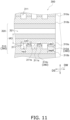
- the heat exchanger 300 is a heat exchanger including a plurality of first heat transfer plates 310, a plurality of second heat transfer plates 320, the casing 160, the first flow pipe 170a, the first flow pipe 170b, the second flow pipe 180a, and the second flow pipe 180b.
- the heat exchanger 300 includes the first heat transfer plates 310 and the second heat transfer plates 320 instead of the first inner fins 110, the second inner fins 120, the partition walls 130, the first separation members 140, and the second separation members 150 of the heat exchanger 100.
- a first flow path 311 through which water flows and a second flow path 321 through which a refrigerant flows are formed inside the heat exchanger 300.
- the heat exchanger 300 includes a fragile portion 390 that prevents the refrigerant flowing through the second flow path 321 from flowing into the first flow path 311 when water freezes.
- the first heat transfer plates 310 and the second heat transfer plates 320 are plate-shaped members made of metal and formed in the same rectangular outer shape. In the present embodiment, as illustrated in Figs. 9 and 10 , the first heat transfer plate 310 and the second heat transfer plate 320 are formed in a rectangular shape elongated in the first direction (longitudinal direction DL), similarly to the first inner fins 110, the second inner fins 120, and the partition walls 130.
- the first heat transfer plates 310 and the second heat transfer plates 320 are alternately stacked along the stacking direction DS and accommodated in the casing 160.
- the number of each of the first heat transfer plates 310 and the second heat transfer plates 320 is not limited, and is appropriately set according to the required performance.
- the first heat transfer plate 310 is a plate-shaped member in which a plurality of first flow paths 311 are formed.
- the first flow path 311 is formed to extend along the longitudinal direction DL in plan view.
- the plurality of first flow paths 311 are formed side by side at a predetermined interval in the width direction DW.
- the first flow path 311 has a rectangular cross-sectional shape taken along a plane perpendicular to the direction in which water flows.
- the first flow path 311 is formed by, for example, but not limited to, etching.
- the first heat transfer plate 310 is formed by stacking a plate-shaped member 310a and a plate-shaped member 310b in the stacking direction DS.
- grooves 311a and 311b are formed by etching so as to face each other to form the first flow path 311 when the plate-shaped members are stacked.
- the plate-shaped member 310a and the plate-shaped member 310b are joined by brazing.
- a portion at which the plate-shaped member 310a and the plate-shaped member 310b are joined to each other and which is located between the adjacent first flow paths 311 in plan view is referred to as a fifth joining portion 310c.
- a portion where the plate-shaped member 310a and the plate-shaped member 310b are joined to each other and which is located between the end portion of the first heat transfer plate 310 in the width direction DW and the first flow path 311 formed closest to the end portion is referred to as a sixth joining portion 310d.
- the fifth joining portion 310c and the sixth joining portion 310d are examples of joining portions.
- the first flow path 311 corresponds to the first flow path 111 of the heat exchanger 100.
- the second heat transfer plate 320 is a plate-shaped member in which a plurality of second flow paths 321 are formed.
- the second flow path 321 is formed so as to extend along the width direction DW in plan view.
- the plurality of second flow paths 321 are formed side by side at a predetermined interval in the longitudinal direction DL.
- the second flow path 321 is formed by, for example, but not limited to, etching.
- the second flow path 321 corresponds to the second flow path 121 of the heat exchanger 100.
- the heat exchanger 300 has the fragile portion 390 that has lower strength than other portions and breaks when the water freezes and expands in volume.
- the first heat transfer plate 310 which is a member forming the first flow path 311, functions as the fragile portion 390.
- the sizes of the respective parts of the first heat transfer plate 310 satisfy the relationship described in (Formula 11) below.
- tw3 represents the interval, in the width direction DW, of the first flow paths 311 formed in the first heat transfer plate 310
- Lw3 represents the sum of the interval tw3 and the width of the first flow path 311 in the width direction DW
- tR3 represents the interval between the first flow path 311 and the second flow path 321 in the stacking direction DS
- hw3 represents the height of the first flow path 311 in the stacking direction DS.
- tw3 is 0.15 mm.
- Lw3 is 2 mm
- tR3 is 0.15 mm
- hw3 is 1 mm.
- the sizes of the respective parts forming the first heat transfer plate 310 further satisfy the relationship described in (Formula 12) below.
- Lsp3 represents the interval in the width direction DW between an end portion of the first heat transfer plate 310 in the width direction DW and the first flow path 311 formed closest to the end portion.
- Lsp3 is 0.1 mm.
- the heat exchanger 300 includes the first heat transfer plate 310 and the second heat transfer plate 320.
- the first heat transfer plate 310 has the first flow path 311 formed therein.
- the second heat transfer plate 320 has the second flow path 321 formed therein.
- the fragile portion 390 is the first heat transfer plate 310.
- the first heat transfer plate 310 forming the first flow path 311 breaks before the other portions.
- the leakage of the refrigerant due to the breakage of the second heat transfer plate 320 forming the second flow path 321 is suppressed.
- a member forming the first flow path 311 functions as the fragile portion 390, but the fragile portion 390 may be a portion where members forming the first flow path 311 are joined to each other.
- the fragile portion 390 may be the fifth joining portion 310c.
- the fragile portion 190 may be the fifth joining portion 310c and the sixth joining portion 310d. In this case, it is preferable that the fifth joining portion 310c breaks first and then the sixth joining portion 310d breaks when the volume expansion of the water reaches or exceeds a certain level.
- the fifth joining portion 310c or the sixth joining portion 310d which functions as the fragile portion 390, breaks before the other portions when the water freezes and expands in volume. Therefore, in the heat exchanger 300 according to Modification 3A, when the water freezes and expands in volume, the leakage of the refrigerant due to the breakage of the member (second heat transfer plate 320) forming the second flow path 321 is suppressed.
- the sizes of the respective parts of the first heat transfer plate 310 forming the first flow path 311 satisfy the relationship described in (Formula 13) below.
- bw5 represents the width of the fifth joining portion 310c in plan view. 0.35 ⁇ bw 5 / 2 ⁇ Lw 3 ⁇ tR 3 / hw 3 ...
- bw5 is 0.035 mm.
- the stress generated between the first flow path 311 and the second flow path 321 is smaller than the stress generated in the fifth joining portion 310c when the water freezes and expands in volume.
- the force generated by the volume expansion can be absorbed by the fifth joining portion 310c, which breaks before the portion between the first flow path 311 and the second flow path 321.
- the leakage of the refrigerant due to the breakage of the member forming the second flow path 321 is suppressed.
- the sizes of the respective parts of the first heat transfer plate 310 forming the first flow path 311 satisfy the relationship described in (Formula 14) below.
- bsp6 represents the width of the sixth joining portion 310d in plan view. 0.35 ⁇ 2 ⁇ bsp 6 + bw 5 / Lw 3 ⁇ 2 ⁇ tR 3 / hw 3 ...
- bsp6 is 0.1 mm.
- the stress generated between the first flow path 311 and the second flow path 321 is smaller than the stress generated in the sixth joining portion 310d when the water freezes and expands in volume.
- the force generated by the volume expansion can be absorbed by the sixth joining portion 310d, which breaks before the portion between the first flow path 311 and the second flow path 321.
- the leakage of the refrigerant due to the breakage of the member (second heat transfer plate 320) forming the second flow path 321 is suppressed.
- the first heat transfer plate 310 is formed by stacking the two plate-shaped members 310a and 310b in which the grooves 311a and 312b forming the first flow path 311 are formed.
- the fragile portion 390 is a portion where the two plate-shaped members 310a and 310b are joined.
- the portions (fifth joining portion 310c, sixth joining portion 310d) where the two plate-shaped members 310a and 310b forming the first heat transfer plate 310 are joined break before the other portions.
- the leakage of the refrigerant due to the breakage of the second heat transfer plate 320 forming the second flow path is suppressed.
- joining in the fifth joining portion 310c and the sixth joining portion 310d is joined by brazing, but the joining in the fifth joining portion 310c and the sixth joining portion 310d may be joined by diffusion joining.
- the fifth joining portion 310c or the sixth joining portion 310d which functions as the fragile portion 390, breaks before the portion between the first flow path 311 and the second flow path 321 when the water freezes and expands in volume. Therefore, in the heat exchanger 300 according to Modification 3B, when the water freezes and expands in volume the leakage of the refrigerant due to the breakage of the member (second heat transfer plate 320) forming the second flow path 321 is suppressed.
- the sizes of the respective parts of the first heat transfer plate 310 forming the first flow path 311 satisfy the relationship described in (Formula 15) below.
- the sizes of the respective parts of the first heat transfer plate 310 forming the first flow path 111 satisfy the relationship described in (Formula 16) below. 2 ⁇ bsp 6 + bw 5 / Lw 3 ⁇ 2 ⁇ tR 3 / hw 3 ...
Landscapes
- Engineering & Computer Science (AREA)
- Physics & Mathematics (AREA)
- Thermal Sciences (AREA)
- Mechanical Engineering (AREA)
- General Engineering & Computer Science (AREA)
- Heat-Exchange Devices With Radiators And Conduit Assemblies (AREA)
Applications Claiming Priority (2)
| Application Number | Priority Date | Filing Date | Title |
|---|---|---|---|
| JP2022114817 | 2022-07-19 | ||
| PCT/JP2023/026469 WO2024019095A1 (ja) | 2022-07-19 | 2023-07-19 | 熱交換器 |
Publications (2)
| Publication Number | Publication Date |
|---|---|
| EP4560247A1 true EP4560247A1 (de) | 2025-05-28 |
| EP4560247A4 EP4560247A4 (de) | 2025-10-22 |
Family
ID=89617833
Family Applications (1)
| Application Number | Title | Priority Date | Filing Date |
|---|---|---|---|
| EP23843018.5A Pending EP4560247A4 (de) | 2022-07-19 | 2023-07-19 | Wärmetauscher |
Country Status (5)
| Country | Link |
|---|---|
| US (1) | US20250137730A1 (de) |
| EP (1) | EP4560247A4 (de) |
| JP (2) | JP7454733B2 (de) |
| CN (1) | CN119384583A (de) |
| WO (1) | WO2024019095A1 (de) |
Families Citing this family (1)
| Publication number | Priority date | Publication date | Assignee | Title |
|---|---|---|---|---|
| JP7727226B1 (ja) * | 2024-03-18 | 2025-08-21 | ダイキン工業株式会社 | 熱交換器及び冷凍装置 |
Family Cites Families (12)
| Publication number | Priority date | Publication date | Assignee | Title |
|---|---|---|---|---|
| US4285041A (en) | 1979-06-22 | 1981-08-18 | Smith Kent G | Digital pacing timer |
| DE3709278A1 (de) * | 1987-03-20 | 1988-09-29 | Kernforschungsz Karlsruhe | Verfahren zur herstellung von feinstrukturkoerpern |
| JP2900898B2 (ja) | 1996-10-28 | 1999-06-02 | ダイキン工業株式会社 | プレート式熱交換器 |
| JP2003294380A (ja) * | 2002-03-29 | 2003-10-15 | Hisaka Works Ltd | 熱交換器 |
| JP2005061778A (ja) * | 2003-08-19 | 2005-03-10 | Calsonic Kansei Corp | 蒸発器 |
| JP2005177921A (ja) * | 2003-12-19 | 2005-07-07 | Zexel Valeo Climate Control Corp | チューブの製造方法、熱交換チューブ、及び熱交換器 |
| JP6843012B2 (ja) * | 2017-07-14 | 2021-03-17 | 株式会社日本クライメイトシステムズ | 熱交換器用チューブ |
| US11662152B2 (en) * | 2018-03-15 | 2023-05-30 | Mitsubishi Electric Corporation | Plate heat exchanger, heat pump device including plate heat exchanger, and heat pump cooling, heating, and hot water supply system including heat pump device |
| WO2020245876A1 (ja) * | 2019-06-03 | 2020-12-10 | 三菱電機株式会社 | プレート式熱交換器及び伝熱装置 |
| US20210333055A1 (en) * | 2020-04-28 | 2021-10-28 | Hamilton Sundstrand Corporation | Stress relieving additively manufactured heat exchanger fin design |
| JP7301224B2 (ja) * | 2020-05-19 | 2023-06-30 | 三菱電機株式会社 | プレート式熱交換器、冷凍サイクル装置および伝熱装置 |
| CN113432461B (zh) * | 2021-05-13 | 2022-12-13 | 江苏远卓设备制造有限公司 | 用于板式换热器的换热片组以及板式换热器 |
-
2023
- 2023-07-19 WO PCT/JP2023/026469 patent/WO2024019095A1/ja not_active Ceased
- 2023-07-19 JP JP2023117269A patent/JP7454733B2/ja active Active
- 2023-07-19 CN CN202380046465.8A patent/CN119384583A/zh active Pending
- 2023-07-19 EP EP23843018.5A patent/EP4560247A4/de active Pending
-
2024
- 2024-02-09 JP JP2024018440A patent/JP2024036686A/ja active Pending
-
2025
- 2025-01-07 US US19/012,587 patent/US20250137730A1/en active Pending
Also Published As
| Publication number | Publication date |
|---|---|
| US20250137730A1 (en) | 2025-05-01 |
| CN119384583A (zh) | 2025-01-28 |
| EP4560247A4 (de) | 2025-10-22 |
| WO2024019095A1 (ja) | 2024-01-25 |
| JP2024036686A (ja) | 2024-03-15 |
| JP7454733B2 (ja) | 2024-03-22 |
| JP2024013229A (ja) | 2024-01-31 |
Similar Documents
| Publication | Publication Date | Title |
|---|---|---|
| EP3205967B1 (de) | Wärmetauscher und klimatisierungsvorrichtung | |
| EP3060868B1 (de) | Wärmetauscher und seitenwand | |
| EP2863159B1 (de) | Wärmetauscher, herstellungsverfahren dafür und kältekreislaufvorrichtung | |
| EP4012296B1 (de) | Wärmetauscher und wärmepumpenvorrichtung | |
| EP2650633B1 (de) | Platten-Wärmetauscher, Herstellungsverfahren dafür und Wärmepumpenvorrichtung | |
| EP3992563A1 (de) | Wärmetauscher und wärmepumpenvorrichtung | |
| EP4130638B1 (de) | Wärmetauscher | |
| US12130057B2 (en) | Heat exchanger, outdoor unit, and refrigeration cycle device | |
| EP4560247A1 (de) | Wärmetauscher | |
| WO2015132963A1 (ja) | 熱交換器及び空気調和機 | |
| EP4556816A1 (de) | Wärmetauscher, kältemittelkreislaufvorrichtung und heisswasserversorgungsvorrichtung | |
| JP2024036686A5 (de) | ||
| EP4163580A1 (de) | Wärmetauscher und kältekreislaufvorrichtung | |
| EP4647707A1 (de) | Wärmetauscher und kühlvorrichtung | |
| EP4155656B1 (de) | Wärmetauscher und wärmetauscherherstellungsverfahren | |
| CN115244344A (zh) | 热泵 | |
| EP4403848A1 (de) | Klimaanlage | |
| EP3734190B1 (de) | Wärmetauscher und kühlzyklusvorrichtung | |
| EP3971507B1 (de) | Wärmetauscher und kühlzyklusvorrichtung | |
| JP7722494B1 (ja) | 熱交換器 | |
| EP4080150A1 (de) | Wärmetauscher, wärmetauschereinheit und kältekreislaufvorrichtung | |
| WO2025158522A1 (ja) | 熱交換器、室外機および冷凍サイクル装置 | |
| WO2025234040A1 (ja) | 熱交換器およびこの熱交換器を備えた冷凍サイクル装置 | |
| EP4043823A1 (de) | Wärmetauscher, wärmetauschereinheit, kältekreislaufvorrichtung und verfahren zur herstellung eines wärmeaustauschelements | |
| WO2025196940A1 (ja) | 熱交換器およびこの熱交換器を備えた冷凍サイクル装置 |
Legal Events
| Date | Code | Title | Description |
|---|---|---|---|
| STAA | Information on the status of an ep patent application or granted ep patent |
Free format text: STATUS: THE INTERNATIONAL PUBLICATION HAS BEEN MADE |
|
| PUAI | Public reference made under article 153(3) epc to a published international application that has entered the european phase |
Free format text: ORIGINAL CODE: 0009012 |
|
| STAA | Information on the status of an ep patent application or granted ep patent |
Free format text: STATUS: REQUEST FOR EXAMINATION WAS MADE |
|
| 17P | Request for examination filed |
Effective date: 20250204 |
|
| AK | Designated contracting states |
Kind code of ref document: A1 Designated state(s): AL AT BE BG CH CY CZ DE DK EE ES FI FR GB GR HR HU IE IS IT LI LT LU LV MC ME MK MT NL NO PL PT RO RS SE SI SK SM TR |
|
| P01 | Opt-out of the competence of the unified patent court (upc) registered |
Free format text: CASE NUMBER: UPC_APP_3796_4560247/2025 Effective date: 20250820 |
|
| A4 | Supplementary search report drawn up and despatched |
Effective date: 20250924 |
|
| DAV | Request for validation of the european patent (deleted) | ||
| DAX | Request for extension of the european patent (deleted) | ||
| RIC1 | Information provided on ipc code assigned before grant |
Ipc: F28F 3/08 20060101AFI20250918BHEP Ipc: F28D 9/02 20060101ALI20250918BHEP Ipc: F28F 3/00 20060101ALI20250918BHEP Ipc: F28D 9/00 20060101ALI20250918BHEP |