EP4560338A1 - Vorrichtung und verfahren zur erkennung von batteriekontaktfehlern - Google Patents
Vorrichtung und verfahren zur erkennung von batteriekontaktfehlern Download PDFInfo
- Publication number
- EP4560338A1 EP4560338A1 EP24169691.3A EP24169691A EP4560338A1 EP 4560338 A1 EP4560338 A1 EP 4560338A1 EP 24169691 A EP24169691 A EP 24169691A EP 4560338 A1 EP4560338 A1 EP 4560338A1
- Authority
- EP
- European Patent Office
- Prior art keywords
- battery
- contact failure
- processor
- battery cells
- abnormal occurrences
- Prior art date
- Legal status (The legal status is an assumption and is not a legal conclusion. Google has not performed a legal analysis and makes no representation as to the accuracy of the status listed.)
- Pending
Links
Images


Classifications
-
- G—PHYSICS
- G01—MEASURING; TESTING
- G01R—MEASURING ELECTRIC VARIABLES; MEASURING MAGNETIC VARIABLES
- G01R31/00—Arrangements for testing electric properties; Arrangements for locating electric faults; Arrangements for electrical testing characterised by what is being tested not provided for elsewhere
- G01R31/36—Arrangements for testing, measuring or monitoring the electrical condition of accumulators or electric batteries, e.g. capacity or state of charge [SoC]
- G01R31/385—Arrangements for measuring battery or accumulator variables
-
- G—PHYSICS
- G01—MEASURING; TESTING
- G01R—MEASURING ELECTRIC VARIABLES; MEASURING MAGNETIC VARIABLES
- G01R31/00—Arrangements for testing electric properties; Arrangements for locating electric faults; Arrangements for electrical testing characterised by what is being tested not provided for elsewhere
- G01R31/50—Testing of electric apparatus, lines, cables or components for short-circuits, continuity, leakage current or incorrect line connections
- G01R31/66—Testing of connections, e.g. of plugs or non-disconnectable joints
-
- G—PHYSICS
- G01—MEASURING; TESTING
- G01R—MEASURING ELECTRIC VARIABLES; MEASURING MAGNETIC VARIABLES
- G01R31/00—Arrangements for testing electric properties; Arrangements for locating electric faults; Arrangements for electrical testing characterised by what is being tested not provided for elsewhere
- G01R31/36—Arrangements for testing, measuring or monitoring the electrical condition of accumulators or electric batteries, e.g. capacity or state of charge [SoC]
- G01R31/382—Arrangements for monitoring battery or accumulator variables, e.g. SoC
- G01R31/3842—Arrangements for monitoring battery or accumulator variables, e.g. SoC combining voltage and current measurements
-
- G—PHYSICS
- G01—MEASURING; TESTING
- G01R—MEASURING ELECTRIC VARIABLES; MEASURING MAGNETIC VARIABLES
- G01R1/00—Details of instruments or arrangements of the types included in groups G01R5/00 - G01R13/00 and G01R31/00
- G01R1/02—General constructional details
- G01R1/04—Housings; Supporting members; Arrangements of terminals
- G01R1/0408—Test fixtures or contact fields; Connectors or connecting adaptors; Test clips; Test sockets
-
- G—PHYSICS
- G01—MEASURING; TESTING
- G01R—MEASURING ELECTRIC VARIABLES; MEASURING MAGNETIC VARIABLES
- G01R19/00—Arrangements for measuring currents or voltages or for indicating presence or sign thereof
- G01R19/10—Measuring sum, difference or ratio
-
- G—PHYSICS
- G01—MEASURING; TESTING
- G01R—MEASURING ELECTRIC VARIABLES; MEASURING MAGNETIC VARIABLES
- G01R19/00—Arrangements for measuring currents or voltages or for indicating presence or sign thereof
- G01R19/165—Indicating that current or voltage is either above or below a predetermined value or within or outside a predetermined range of values
- G01R19/16566—Circuits and arrangements for comparing voltage or current with one or several thresholds and for indicating the result not covered by subgroups G01R19/16504, G01R19/16528, G01R19/16533
- G01R19/16576—Circuits and arrangements for comparing voltage or current with one or several thresholds and for indicating the result not covered by subgroups G01R19/16504, G01R19/16528, G01R19/16533 comparing DC or AC voltage with one threshold
-
- G—PHYSICS
- G01—MEASURING; TESTING
- G01R—MEASURING ELECTRIC VARIABLES; MEASURING MAGNETIC VARIABLES
- G01R27/00—Arrangements for measuring resistance, reactance, impedance, or electric characteristics derived therefrom
- G01R27/02—Measuring real or complex resistance, reactance, impedance, or other two-pole characteristics derived therefrom, e.g. time constant
- G01R27/20—Measuring earth resistance; Measuring contact resistance, e.g. of earth connections, e.g. plates
- G01R27/205—Measuring contact resistance of connections, e.g. of earth connections
-
- G—PHYSICS
- G01—MEASURING; TESTING
- G01R—MEASURING ELECTRIC VARIABLES; MEASURING MAGNETIC VARIABLES
- G01R31/00—Arrangements for testing electric properties; Arrangements for locating electric faults; Arrangements for electrical testing characterised by what is being tested not provided for elsewhere
- G01R31/36—Arrangements for testing, measuring or monitoring the electrical condition of accumulators or electric batteries, e.g. capacity or state of charge [SoC]
- G01R31/396—Acquisition or processing of data for testing or for monitoring individual cells or groups of cells within a battery
-
- G—PHYSICS
- G01—MEASURING; TESTING
- G01R—MEASURING ELECTRIC VARIABLES; MEASURING MAGNETIC VARIABLES
- G01R31/00—Arrangements for testing electric properties; Arrangements for locating electric faults; Arrangements for electrical testing characterised by what is being tested not provided for elsewhere
- G01R31/50—Testing of electric apparatus, lines, cables or components for short-circuits, continuity, leakage current or incorrect line connections
- G01R31/52—Testing for short-circuits, leakage current or ground faults
-
- G—PHYSICS
- G01—MEASURING; TESTING
- G01R—MEASURING ELECTRIC VARIABLES; MEASURING MAGNETIC VARIABLES
- G01R31/00—Arrangements for testing electric properties; Arrangements for locating electric faults; Arrangements for electrical testing characterised by what is being tested not provided for elsewhere
- G01R31/50—Testing of electric apparatus, lines, cables or components for short-circuits, continuity, leakage current or incorrect line connections
- G01R31/54—Testing for continuity
-
- H—ELECTRICITY
- H01—ELECTRIC ELEMENTS
- H01M—PROCESSES OR MEANS, e.g. BATTERIES, FOR THE DIRECT CONVERSION OF CHEMICAL ENERGY INTO ELECTRICAL ENERGY
- H01M10/00—Secondary cells; Manufacture thereof
- H01M10/42—Methods or arrangements for servicing or maintenance of secondary cells or secondary half-cells
- H01M10/425—Structural combination with electronic components, e.g. electronic circuits integrated to the outside of the casing
-
- Y—GENERAL TAGGING OF NEW TECHNOLOGICAL DEVELOPMENTS; GENERAL TAGGING OF CROSS-SECTIONAL TECHNOLOGIES SPANNING OVER SEVERAL SECTIONS OF THE IPC; TECHNICAL SUBJECTS COVERED BY FORMER USPC CROSS-REFERENCE ART COLLECTIONS [XRACs] AND DIGESTS
- Y02—TECHNOLOGIES OR APPLICATIONS FOR MITIGATION OR ADAPTATION AGAINST CLIMATE CHANGE
- Y02E—REDUCTION OF GREENHOUSE GAS [GHG] EMISSIONS, RELATED TO ENERGY GENERATION, TRANSMISSION OR DISTRIBUTION
- Y02E60/00—Enabling technologies; Technologies with a potential or indirect contribution to GHG emissions mitigation
- Y02E60/10—Energy storage using batteries
Definitions
- aspects of embodiments of the present disclosure relate to a device and method capable of detecting a contact failure in a battery.
- a secondary battery is a battery that can be repeatedly charged and discharged, unlike a primary battery that cannot be recharged.
- Low-capacity secondary batteries are used in small portable electronic devices such as smartphones, feature phones, notebook computers, digital cameras, and camcorders, and high-capacity secondary batteries are widely used as driving power sources and power storage batteries for motors in hybrid and electric vehicles.
- Such a secondary battery includes an electrode assembly provided with a positive electrode and a negative electrode, a case for accommodating the electrode assembly, electrode terminals connected to the electrode assembly, and the like.
- a contact failure may occur among a busbar, a contactor, a fuse, and a cell.
- a voltage value is changed and recognized as an over voltage or an under voltage according to a current direction (charging or discharging), and thus a contact failure can be detected.
- a method of detecting a secondary failure e.g., melting of contact portions due to high temperatures, or sudden output loss due to sudden opening of high voltage components such as busbars
- a contact failure among a busbar, a contactor, a fuse, and a cell in a high-voltage battery in advance is required.
- the present invention is directed to providing a battery contact failure detecting device and a method that detect a secondary failure that can occur due to a contact failure among a busbar, a contactor, a fuse, and a cell in a high-voltage battery in advance to stably use the high-voltage battery.
- a battery contact failure detecting device including: a battery module formed of a plurality of battery cells; a connecting part which includes at least one of a busbar, a contactor, and a fuse and connects the battery cells to each other; a sensor which measures a current and a voltage of each of the battery cells; and a processor which counts a number of abnormal occurrences on the basis of the current and voltage measured by the sensor to detect a contact failure of the battery cells due to a short circuit or open circuit of the connecting part.
- the processor may count the number of abnormal occurrences on the basis of the current measured by the sensor and a voltage difference between the battery cells.
- the processor may be configured to determine that an abnormality occurs and count the number of abnormal occurrences.
- the processor may count the number of abnormal occurrences when the first condition and the second condition are satisfied for a reference time.
- the processor may count the number of abnormal occurrences in units of times that are each preset to be smaller than a time for detecting an over voltage or an under voltage.
- the processor may restrict use of the battery according to whether a contact failure of the battery cells is detected.
- the processor may restrict use of the battery when the number of abnormal occurrences greater than or equal to a first set number is counted in succession.
- the processor may restrict use of the battery when an accumulated number of abnormal occurrences greater than or equal to a second set number is counted.
- a battery contact failure detecting method comprising: measuring, by a sensor, a current and a voltage of each of a plurality of battery cells; counting, by a processor, a number of abnormal occurrences on the basis of the current and voltage measured by the sensor; and detecting, by the processor, a contact failure of the battery cells due to a short circuit or open circuit of a connecting part which connects the battery cells to each other on the basis of the counted number of abnormal occurrences.
- the counting of the number of abnormal occurrences may include counting the number of abnormal occurrences on the basis of the current measured by the sensor and a voltage difference between the battery cells.
- the counting of the number of abnormal occurrences may include determining whether a first condition that the current measured by the sensor is greater than or equal to a specific current is satisfied, determining whether a second condition that the voltage difference between the battery cells is greater than or equal to a preset reference value is satisfied, determining that an abnormality occurs when the first condition and the second condition are satisfied, and counting the number of abnormal occurrences.
- the counting of the number of abnormal occurrences may include counting the number of abnormal occurrences when the first condition and the second condition are satisfied for a reference time.
- the counting of the number of abnormal occurrences may include counting the number of abnormal occurrences in units of times that are each preset to be smaller than a time for detecting an over voltage or an under voltage.
- the battery contact failure detecting method may further comprise restricting, by the processor, use of the battery according to whether the contact failure of the battery cells is detected.
- the restricting of the use of the battery may include restricting the use of the battery when the number of abnormal occurrences greater than or equal to a first set number is counted in succession and/or when an accumulated number of abnormal occurrences greater than or equal to a second set number is counted.
- a case in which a first element is disposed "over (or under)” or “above (or below)” a second element may include a case in which the first element is disposed in contact with an upper (or lower) surface of the second element or a case in which a third element is interposed between the first element and the second element disposed over (or under) the first element.
- first element When a first element is referred to as being “connected,” “coupled,” or “bonded” to a second element, although the first element may be directly connected or bonded to the second element, it should be understood that a third element may be interposed therebetween, or the elements may be connected, coupled, or bonded through other elements.
- first part when a first part is referred to as being “electrically connected” to a second part, it includes not only a case in which the first part is “directly connected” to the second part but also a case in which the first part is “connected” to the second part with a third element interposed therebetween.
- a and/or B means “A,” “B,” or “A and B.” That is “and/or” includes all combinations or any combination of a plurality of listed items.
- C to D means “more than or equal to C and less than or equal to D.”
- FIG. 1 is a perspective view illustrating an example of a battery module according to an embodiment of the present invention.
- a battery module 100 includes a plurality of battery cells 10 which include terminal parts 11 and 12 and are arrayed (e.g., stacked) in one direction, a connecting tab 20 that connects a battery cell 10a and an adjacent battery cell 10b, and a protection circuit module 30 of which one end portion is connected to the connecting tab 20.
- the protection circuit module 30 may be a battery management system (BMS).
- BMS battery management system
- the connecting tab 20 may include a body portion 22 in contact with the terminal parts 11 and 12 between the battery cells 10a and 10b and an extension portion which extends from the body portion 22 and is connected to the protection circuit module 30.
- the connecting tab 20 may be a busbar.
- the battery cell 10 may be formed with a battery case and an electrode assembly and an electrolyte, which are accommodated in the battery case.
- the electrode assembly and the electrolyte generate energy by electrochemically reacting to each other.
- the terminal parts 11 and 12 electrically connected to the connecting tab 20 and a vent 13 which is a discharge passage of gas generated therein may be provided on one side of the battery cell 10.
- the terminal parts 11 and 12 of the battery cell 10 may be a positive terminal 11 and a negative terminal 12 which have different polarities, and the terminal parts 11 and 12 of the adjacent battery cells 10a and 10b may be electrically connected in series or parallel by the connecting tab 20 which will be described further below.
- serial connection has been illustrated and described above, the present invention is not limited to such a structure, and any of various suitable connection structures may be used as desired.
- the number and an array of the battery cells 10 are not limited to the structure illustrated in FIG. 1 and may be changed as desired.
- a plurality of battery cells 10 may be arrayed (e.g., stacked) in one direction so that wide surfaces of the battery cells 10 face each other, and the arrayed plurality of battery cells 10 may be fixed by housings 61, 62, 63, and 64.
- the housings 61, 62, 63, and 64 may include a pair of end plates 61 and 62 facing the wide surfaces of the battery cells 10 and side plates 63 and a bottom plate 64 which connect the pair of end plates 61 and 62.
- the side plates 63 may support side surfaces of the battery cells 10, and the bottom plate 64 may support bottom surfaces of the battery cells 10.
- the pair of end plates 61 and 62 and the side plates 63 and the bottom plate 64 may be connected by members such as bolts 65.
- the protection circuit module 30, on which electric components, protection circuits, and the like are mounted, may be electrically connected to the connecting tab 20 which will be described further below.
- the protection circuit module 30 may include a first protection circuit module 30a and a second protection circuit module 30b which extend at different locations in a direction in which the plurality of battery cells 10 are arrayed (e.g., stacked).
- the first protection circuit module 30a and the second protection circuit module 30b may be spaced at a set or predetermined distance to be located in parallel and connected to the adjacent connecting tab 20.
- the first protection circuit module 30a may be formed on one upper side of the plurality of battery cells 10 to extend in the direction in which the plurality of battery cells 10 are arrayed (e.g., stacked), and the second protection circuit modules 30b may be formed on the other upper side of the plurality of battery cells 10 to extend in the direction in which the plurality of battery cells 10 are arrayed (e.g., stacked).
- the second protection circuit module 30b may be located to be spaced the set or predetermined distance from the first protection circuit module 30a with the vent 13 interposed therebetween and disposed parallel to the first protection circuit module 30a.
- the first protection circuit module 30a and the second protection circuit module 30b may be connected to each other by a conductive connecting member 50.
- one side of the connecting member 50 may be connected to the first protection circuit module 30a, the other side thereof may be connected to the second protection circuit module 30b, and thus electric connection between the two protection circuit modules may be completed.
- the connection may be performed by any one method of soldering, resistance welding, laser welding, and projection welding methods, or the like.
- the connecting member 50 may be an electric wire.
- the connecting member 50 may be formed of an elastic or flexible material. Whether voltages, temperatures, and currents of the plurality of battery cells 10 are normal may be checked and managed through the connecting member 50. That is, information of voltages, currents, temperatures, and the like transmitted to the first protection circuit module from adjacent connecting tabs and information of voltages, currents, temperatures, and the like transmitted to the second protection circuit module from adjacent connecting tabs may be integrally managed by the protection circuit module through the connecting member.
- a shape and a structure of the connecting member 50 are not limited to those illustrated in FIG. 1 , and the connecting members 50 may have any suitable shape or structure.
- the protection circuit module 30 is provided with the first and the second protection circuit modules 30a and 30b, the area of the PCB constituting the protection circuit module can be reduced (e.g., minimized), and thus space in the battery module can be secured. Accordingly, fastening work of connecting the connecting tab 20 and the protection circuit module 30 and repairing work when an abnormality of the battery module is detected are easily performed to improve (e.g., increase) operation efficiency.
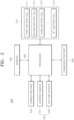
- FIG. 2 is a block diagram of a battery contact failure detecting device according to an embodiment of the present invention.
- a battery contact failure detecting device 200 may include a battery module 210, a connecting part 220, a sensor 230, a processor 240, a memory 250, and a communication part 260.
- the battery module 210 may include a plurality of battery cells, that is, a first battery cell 211 to an n th battery cell 214.
- the plurality of battery cells 211 to 214 may be connected in series or parallel.
- the connecting part 220 may include at least one of a busbar, a contactor, and a fuse.
- the connecting part 220 may serve to connect the battery cells 211 to 214.
- the contactor may block an output of the battery module 210 or power supplied to the battery module 210 from the outside.
- the contactor may be selectively turned on or off according to a control command of the processor 240.
- the contactor may be implemented as a relay such as a mechanical contactor which is selectively turned on/off by a magnetic force of a coil.
- the contactor may be implemented as a semiconductor switch such as a metal-oxide-semiconductor field-effect transistor (MOSFET).
- MOSFET metal-oxide-semiconductor field-effect transistor
- the sensor 230 may measure a current and a voltage of each of the battery cells 211 to 214. To this end, the sensor 230 may include a current sensor 231 and a voltage sensor 232.
- the current sensor 231 may measure a current of the battery module 210.
- the current sensor 231 may include a plurality of current sensors 231 to measure the current of each of the battery cells 211 to 214.
- the current sensor 231 may be connected to at least one of an input terminal and an output terminal of each of the battery cells 211 to 214 to measure the current.
- the voltage sensor 232 may measure a voltage of the battery module 210.
- the voltage sensor 232 may include a plurality of voltage sensors 232 to measure the voltage of each of the battery cells 211 to 214.
- the voltage sensor 232 may be connected to at least one of the input terminal and the output terminal of each of the battery cells 211 to 214 to measure the voltage.
- the processor 240 may monitor a state of each of the plurality of battery cells 211 to 214, determine a state of charge (SOC), and calculate a state of health (SOH).
- the processor 240 may detect a failure of the battery module 210 and the plurality of battery cells 211 to 214.
- the processor 240 may control charging and discharging of the plurality of battery cells 211 to 214, control temperatures of the battery cells 211 to 214, and perform balancing control. In addition, the processor 240 may perform at least one protection function among over-discharge prevention, over-charge prevention, over-current prevention, short circuit prevention, and fire extinguishing functions on the basis of a state monitoring result.
- the processor 240 may include any one of a battery management system (BMS), a battery pack control module (BPCM), a central processing unit (CPU), an electronic control unit (ECU), and a micro controller unit (MCU).
- BMS battery management system
- BPCM battery pack control module
- CPU central processing unit
- ECU electronice control unit
- MCU micro controller unit
- the processor 240 may count the number of abnormal occurrences on the basis of a current measured by the current sensor 231 and a voltage measured by the voltage sensor 232.
- the processor 240 may count the number of abnormal occurrences on the basis of the current measured by the sensor 230, and a voltage difference between the battery cells 211 to 214.
- the processor 240 may determine that an abnormality occurs and count the number of abnormal occurrences.
- the processor 240 may determine that the first condition is satisfied. In some embodiments, when a current measured by the sensor 230 is greater than 100 A, the processor 240 may determine that the first condition is satisfied.
- the processor 240 may determine that the second condition is satisfied. In some embodiments, when a voltage difference between the battery cells 211 to 214 is greater than 600 mV, the processor 240 may determine that the second condition is satisfied.
- the processor 240 may count the number of abnormal occurrences.
- a process of counting the number of abnormal occurrences may be performed in units of preset times, wherein, for example, each of the preset times may be smaller than a time for detecting an over voltage or an under voltage condition, that is, the process may be performed for a set or predetermined time in the range of, for example, 200 ms to 300 ms.
- the processor 240 may detect a contact failure of each of the battery cells 211 to 214 due to a short circuit or open circuit of the connecting part 220 on the basis of the counted number of abnormal occurrences.
- the processor 240 may restrict use of the battery according to whether the contact failure of each of the battery cells 211 to 214 occurs.
- the processor 240 may restrict use of the battery.
- the processor 240 may restrict use of the battery.
- the memory 250 may store current data and voltage data input from the sensor 230, set data for processing the current data or voltage data, data about the battery module 210, reference data for determining a state of the battery module 210, SOC data of the battery module 210 or the battery cells 211 to 214, data generated during an operation process of the processor 240, and/or the like.
- the memory 250 may store data for detecting damage to the battery cells 211 to 214 on the basis of the current data and the voltage data, for example, level data, weight data, cumulated weight data, specified range data, cell damage range data, and/or the like.
- the memory 250 may include data about at least one of a data processing algorithm, a data level determination algorithm, a weight setting algorithm, a damage prediction algorithm, a contactor control algorithm, and a battery diagnosis algorithm.
- the memory 250 may include a storage medium such as a random-access memory (RAM) and a non-volatile memory such as a read-only memory (ROM), an electrically erased programmable ROM (EEPROM), a flash memory, and/or the like.
- RAM random-access memory
- ROM read-only memory
- EEPROM electrically erased programmable ROM
- flash memory and/or the like.
- the communication part 260 may transmit and receive data to and from the battery module 210, the connecting part 220, the sensor 230, the processor 240, and the memory 250. In addition, the communication part 260 may transmit and receive data to and from main a processor (not shown) of an apparatus or device including the processor 240 and the battery contact failure detecting device 200.
- the communication part 260 may include a controller area network (CAN) or local interconnect network (LIN) communication driver to transmit and receive data.
- the communication part 260 may transmit and receive data through serial or parallel communication.
- CAN controller area network
- LIN local interconnect network
- FIG. 3 is a signal diagram illustrating an example of a current waveform for counting the number of abnormal occurrences according to some embodiments of the present invention.
- FIG. 4 is a signal diagram illustrating an example of a voltage difference waveform between the cells for counting the number of abnormal occurrences according to an embodiment of the present invention.
- the processor 240 may determine that an abnormality occurs in the battery cells 211 to 214 and count the number of abnormal occurrences.
- the processor 240 may count the number of abnormal occurrences.
- the processor 240 may perform a process of counting the number of abnormal occurrences in units of preset times for a time in the range of 200 to 300 ms which is smaller than a mature time (e.g., three seconds) which is a time for detecting an over voltage or an under voltage.
- the processor 240 may recognize the sequential abnormalities as a problem situation and restrict use of the battery to stably manage the battery. In addition, the processor 240 may restrict use of the battery even when the accumulated number of abnormal occurrences (which may include even non-successive abnormal occurrences) is greater than or equal to 100.
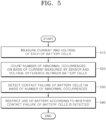
- FIG. 5 is a flow diagram for describing a battery contact failure detecting method according to an embodiment of the present invention.
- the battery contact failure detecting method which will be described further below is representative of only an embodiment of the present invention.
- various suitable operations may be added in addition thereto as described further below, the following operations may be performed in a different order, and thus the present disclosure is not limited to the operations and order which will be described further below.
- the sensor 230 may measure a current and a voltage of each of the battery cells 211 to 214.
- the processor 240 may count the number of abnormal occurrences on the basis of the current measured by the sensor 230 and a voltage difference between the battery cells 211 to 214.
- a contact failure of each of the battery cells 211 to 214 due to a short circuit or open circuit of the connecting part 220 may be detected on the basis of the counted number of abnormal occurrences.
- the processor 240 may restrict use of the battery according to whether the contact failure of each of the battery cells 211 to 214 occurs.
- a voltage which becomes different from an actual voltage due to a contact resistance when the contact resistance increases and a high current flows is used as a method of detecting a secondary failure (such as melting of contact portions due to high temperatures, or sudden output loss due to sudden opening of high voltage components such as busbars) which can occur due to a contact failure among a busbar, a contactor, a fuse, and a cell in a high-voltage battery in advance, and thus a battery contact failure can be efficiently detected.
- a secondary failure such as melting of contact portions due to high temperatures, or sudden output loss due to sudden opening of high voltage components such as busbars
- a phenomenon in which a voltage difference occurs whenever a high current flows is used to count the number of times in units of several hundreds of ms (e.g., 200 ms to 300 ms) much smaller than the conventional mature time (e.g., 3 seconds)
- a battery contact failure problem due to an open circuit of a connecting part such as a busbar, a contactor, or a fuse can be recognized even within a short time, and when the number of abnormal occurrences greater than or equal to a set number is counted, it can be detected as a problem.
- the present invention described in this specification can be implemented through, for example, a method, a process, an apparatus, a software program, a data stream, or a signal. Even when the present invention is described as being implemented in only a single form (for example, as the method), the described features may be implemented in another form (for example, as the apparatus or program).
- the apparatus may be implemented using proper hardware, software, firmware, or the like.
- the method may be implemented in an apparatus such as a processor which is generally a processing device such as a computer, a microprocessor, an integrated circuit, or a programmable logic device.
- the processor includes a communication device such as a computer, a cell phone, a portable/personal digital assistant (PDA) terminal, and other devices which facilitate information communication between final users.
- PDA portable/personal digital assistant
- the processor may be implemented as a CPU or system on chip (SoC), may drive an operating system or application to control a plurality of hardware or software components connected to the processor, and may perform various suitable types of data processing and operations.
- SoC system on chip
- the processor may be configured to execute at least one command stored in the memory and store result data of the execution in the memory.
Landscapes
- Physics & Mathematics (AREA)
- General Physics & Mathematics (AREA)
- Engineering & Computer Science (AREA)
- Manufacturing & Machinery (AREA)
- Chemical & Material Sciences (AREA)
- Chemical Kinetics & Catalysis (AREA)
- Electrochemistry (AREA)
- General Chemical & Material Sciences (AREA)
- Power Engineering (AREA)
- Microelectronics & Electronic Packaging (AREA)
- Secondary Cells (AREA)
Applications Claiming Priority (1)
| Application Number | Priority Date | Filing Date | Title |
|---|---|---|---|
| KR1020230161871A KR20250074919A (ko) | 2023-11-21 | 2023-11-21 | 배터리 접촉 불량 검출 장치 및 방법 |
Publications (1)
| Publication Number | Publication Date |
|---|---|
| EP4560338A1 true EP4560338A1 (de) | 2025-05-28 |
Family
ID=90721114
Family Applications (1)
| Application Number | Title | Priority Date | Filing Date |
|---|---|---|---|
| EP24169691.3A Pending EP4560338A1 (de) | 2023-11-21 | 2024-04-11 | Vorrichtung und verfahren zur erkennung von batteriekontaktfehlern |
Country Status (4)
| Country | Link |
|---|---|
| US (1) | US20250164567A1 (de) |
| EP (1) | EP4560338A1 (de) |
| KR (1) | KR20250074919A (de) |
| CN (1) | CN120028711A (de) |
Citations (5)
| Publication number | Priority date | Publication date | Assignee | Title |
|---|---|---|---|---|
| KR20160068522A (ko) * | 2014-12-05 | 2016-06-15 | 현대오트론 주식회사 | 배터리 버스바의 고장 진단 장치 및 방법 |
| US20190235009A1 (en) * | 2018-01-29 | 2019-08-01 | Toyota Jidosha Kabushiki Kaisha | Electric storage system and detection method of looseness in fastening part of electric storage system |
| JP2021089871A (ja) * | 2019-12-05 | 2021-06-10 | 東芝インフラシステムズ株式会社 | 蓄電池装置、方法及びプログラム |
| US20220341997A1 (en) * | 2020-05-15 | 2022-10-27 | Lg Energy Solution, Ltd. | Apparatus and Method for Diagnosing a Battery |
| US20230251315A1 (en) * | 2021-01-21 | 2023-08-10 | Lg Energy Solution, Ltd. | Busbar diagnosis device, battery pack, energy storage system, and busbar diagnosis method |
-
2023
- 2023-11-21 KR KR1020230161871A patent/KR20250074919A/ko active Pending
-
2024
- 2024-03-13 US US18/604,282 patent/US20250164567A1/en active Pending
- 2024-04-11 EP EP24169691.3A patent/EP4560338A1/de active Pending
- 2024-04-12 CN CN202410440678.5A patent/CN120028711A/zh active Pending
Patent Citations (5)
| Publication number | Priority date | Publication date | Assignee | Title |
|---|---|---|---|---|
| KR20160068522A (ko) * | 2014-12-05 | 2016-06-15 | 현대오트론 주식회사 | 배터리 버스바의 고장 진단 장치 및 방법 |
| US20190235009A1 (en) * | 2018-01-29 | 2019-08-01 | Toyota Jidosha Kabushiki Kaisha | Electric storage system and detection method of looseness in fastening part of electric storage system |
| JP2021089871A (ja) * | 2019-12-05 | 2021-06-10 | 東芝インフラシステムズ株式会社 | 蓄電池装置、方法及びプログラム |
| US20220341997A1 (en) * | 2020-05-15 | 2022-10-27 | Lg Energy Solution, Ltd. | Apparatus and Method for Diagnosing a Battery |
| US20230251315A1 (en) * | 2021-01-21 | 2023-08-10 | Lg Energy Solution, Ltd. | Busbar diagnosis device, battery pack, energy storage system, and busbar diagnosis method |
Also Published As
| Publication number | Publication date |
|---|---|
| CN120028711A (zh) | 2025-05-23 |
| US20250164567A1 (en) | 2025-05-22 |
| KR20250074919A (ko) | 2025-05-28 |
Similar Documents
| Publication | Publication Date | Title |
|---|---|---|
| CN108604715B (zh) | 电池组件和充放电控制方法 | |
| JP4798548B2 (ja) | 電池パック | |
| CN111630398B (zh) | 电池管理设备和包括该电池管理设备的电池组和车辆 | |
| KR102609865B1 (ko) | 배터리 팩 및 이를 포함하는 전자 장치 | |
| KR20150107032A (ko) | 배터리 팩 | |
| US12609423B2 (en) | Relay control system and battery system | |
| EP4560338A1 (de) | Vorrichtung und verfahren zur erkennung von batteriekontaktfehlern | |
| US20250183386A1 (en) | Apparatus for deactivating battery module, battery pack including the same, and method of deactivating battery module | |
| KR20230111655A (ko) | 배터리 연결 장치, 배터리 시스템 및 이들의 동작 방법 | |
| CN120691525A (zh) | 用于电池的充电控制方法和充电控制设备 | |
| US12199421B2 (en) | Battery disconnect unit including moving plate | |
| EP3471172B1 (de) | Lösbare sammelschiene für ein batteriesystem und batteriesystem damit | |
| EP4654430A2 (de) | Vorrichtung und verfahren zur verhinderung von batterieüberladung und batteriepack | |
| EP4568056A1 (de) | Batteriepackgruppe und ansteuerungsverfahren dafür | |
| US20250125430A1 (en) | Apparatus and method for predicting damage to battery cell | |
| US20250364609A1 (en) | Battery device, operating method thereof, and battery pack | |
| EP4553513A1 (de) | Batteriepacksteuerungsvorrichtung und verfahren zur fehlerfixierung eines relais | |
| CN222190868U (zh) | 电池诊断设备以及电池系统 | |
| US20200152947A1 (en) | Battery System Monitoring Device and Battery Pack | |
| EP4557446A2 (de) | Wiederaufladbare batterie und wiederaufladbares batteriemodul | |
| US20250286208A1 (en) | Secondary battery and secondary battery module including the same | |
| EP4124498A1 (de) | Relaissteuerungssystem und batteriesystem | |
| JP2025122229A (ja) | 欠陥のあるバッテリーセルの検出方法およびその方法を提供するバッテリー管理システム | |
| US11075411B2 (en) | Protection circuit module, battery pack, and method of manufacturing the battery pack | |
| JP2025183925A (ja) | バッテリー診断装置および方法、バッテリーパック |
Legal Events
| Date | Code | Title | Description |
|---|---|---|---|
| PUAI | Public reference made under article 153(3) epc to a published international application that has entered the european phase |
Free format text: ORIGINAL CODE: 0009012 |
|
| STAA | Information on the status of an ep patent application or granted ep patent |
Free format text: STATUS: REQUEST FOR EXAMINATION WAS MADE |
|
| 17P | Request for examination filed |
Effective date: 20240411 |
|
| AK | Designated contracting states |
Kind code of ref document: A1 Designated state(s): AL AT BE BG CH CY CZ DE DK EE ES FI FR GB GR HR HU IE IS IT LI LT LU LV MC ME MK MT NL NO PL PT RO RS SE SI SK SM TR |