EP4560408A1 - Gangreserve-anzeigevorrichtung für eine uhr - Google Patents
Gangreserve-anzeigevorrichtung für eine uhr Download PDFInfo
- Publication number
- EP4560408A1 EP4560408A1 EP23211378.7A EP23211378A EP4560408A1 EP 4560408 A1 EP4560408 A1 EP 4560408A1 EP 23211378 A EP23211378 A EP 23211378A EP 4560408 A1 EP4560408 A1 EP 4560408A1
- Authority
- EP
- European Patent Office
- Prior art keywords
- cam
- shaft
- barrel
- threaded portion
- ratchet
- Prior art date
- Legal status (The legal status is an assumption and is not a legal conclusion. Google has not performed a legal analysis and makes no representation as to the accuracy of the status listed.)
- Withdrawn
Links
Images

Classifications
-
- G—PHYSICS
- G04—HOROLOGY
- G04B—MECHANICALLY-DRIVEN CLOCKS OR WATCHES; MECHANICAL PARTS OF CLOCKS OR WATCHES IN GENERAL; TIME PIECES USING THE POSITION OF THE SUN, MOON OR STARS
- G04B9/00—Supervision of the state of winding, e.g. indicating the amount of winding
- G04B9/005—Supervision of the state of winding, e.g. indicating the amount of winding by optical indication of the amount of winding
Definitions
- the present invention relates to a power reserve indicator device for a mechanical timepiece provided with at least one barrel and capable of indicating to a user when the barrel spring has reached a predetermined winding or diswinding threshold.
- Power reserve indicator devices are commonly used in mechanical timepieces to inform the user at all times of the winding status of the barrel spring. This allows the user to wind the timepiece in time to avoid stopping the movement and the resulting necessary time adjustment.
- conventional power reserve indicator devices do not provide information to the user during winding as soon as the barrel spring has reached a predetermined winding threshold in particular. Also, these devices do not provide information to the user that such a threshold has been reached and, for this purpose, do not suggest a simple indicator means which is also disengageable.
- CH95250 discloses an example of a power reserve indicator device having the aforementioned drawback.
- This device comprises in particular a nut mounted to move on a threaded portion of a shaft in one direction and in an opposite direction during the winding and diswinding of the barrel spring respectively.
- This nut is arranged to cooperate with a rocker connected to a power reserve indicator.
- the publications CH287930 And DE34115 disclose a power reserve indicator device comprising at least part of the above-mentioned characteristics.
- CH702847A1 discloses a power reserve indicator device whose indicator movement speed is non-linear. This device comprises a non-linear sector display of the power reserve having a larger reading range at the end of the power reserve along which the indicator moves at a higher speed. A more accurate reading of the power reserve at the end of the power reserve is thus obtained in order to allow the user to wind the timepiece in time.
- An aim of the present invention is therefore to propose a power reserve indicator device for a mechanical timepiece which is at least partly free from the above-mentioned limitations.
- an aim of the present invention is to propose a power reserve indicator device capable of informing the user as soon as the barrel spring has reached a predetermined winding threshold during the winding of the timepiece.
- Another aim of the present invention is to provide a power reserve indicator device capable of informing the user as soon as the barrel spring has reached a predetermined winding threshold to allow the user to wind the timepiece in time.
- a power reserve indicator device for a timepiece comprising a barrel including a barrel spring, a barrel arbor secured to the spring and a ratchet secured to the barrel arbor.
- the device comprises a arbor comprising a threaded portion and intended to be rotated by one of the ratchet and the barrel, a cam intended to be rotated by the other of the ratchet and the barrel, a lever comprising an actuable part arranged to cooperate with a peripheral portion of the cam in order to position the lever according to the position of the cam along the arbor, and an indicator connected to the lever to indicate the level of the power reserve.
- the cam comprises a thread adapted to engage the threaded portion of the arbor in order to allow axial movement of the cam along the arbor in one direction and in an opposite direction during the winding and diswinding of the barrel spring respectively.
- the cam is arranged to be brought into a position disengaged from the threaded portion of the shaft when the barrel spring has reached a winding threshold or a disengaging threshold.
- the device further comprises holding means for holding the thread of the cam coaxially with the axis of the shaft and against the last thread of the threaded portion in said disengaged position.
- the holding means comprise a constraint member arranged to act on the cam so that the threading of the cam remains under pressure against the threaded portion of the shaft in said released position.
- the holding means comprise, on the one hand, a cylindrical bearing surface forming an integral part of the shaft and, on the other hand, a cylindrical opening forming an integral part of the cam and opening into the thread.
- the wall of the cylindrical opening is arranged to bear against the cylindrical bearing surface in said released position.
- the shaft further comprises an unthreaded portion arranged between the threaded portion and the cylindrical bearing surface.
- the tapping of the cam is located at the unthreaded portion in said disengaged position.
- the device further comprises a winding wheel intended to be driven by the ratchet and a winding wheel intended to be driven by the barrel.
- the shaft is rotationally fixed to the winding wheel.
- the cam is rotationally fixed to the winding wheel by means of a connecting element arranged to move around the shaft during the axial movement of the cam in one of the two directions.
- the winding wheel and the winding wheel are mounted coaxially.
- the connecting element is in the form of a rod secured to the unwinding wheel.
- the axis of the rod is parallel to the axis of the shaft.
- the rod passes right through the cam so that the latter can slide along the rod.
- the rod is integral with a hub of the disarming wheel.
- the hub comprises a housing arranged to receive a lower portion of the cam when the barrel spring is in a disarmed state.
- the rocker comprises a board provided with a rack engaged with a pinion connected to the indicator.
- the board is arranged to pivot in a plane orthogonal to the direction of movement of the cam.
- the rocker comprises a pivot body configured so that the pivot axis of the rocker is parallel to the direction of movement of the cam.
- the pivot body incorporates the actuable part, which comprises a portion inclined relative to said pivot axis.
- the peripheral portion of the cam comprises a truncated cone-shaped surface intended to cooperate with the actuable part of the rocker.
- the inclination of said inclined portion is different from the inclination of said frustoconical surface.
- the device further comprises a bridge configured to receive in particular one end of the shaft.
- the constraint member is arranged between the bridge and the cam.
- a timepiece comprising a barrel provided with a drum, a ratchet and the power reserve indicator device according to one of the aforementioned embodiments.
- the drum and the ratchet are kinematically connected respectively to the winding wheel and the winding wheel.
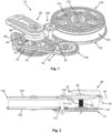
- the power reserve indicator device illustrated, without limitation, by the figures represents a preferred embodiment. More particularly, with reference to the Figures 1 and 2 , the device 10 is arranged to cooperate with a barrel 100 comprising a barrel spring 101, a barrel shaft 103 secured to the barrel spring at one of its ends and a ratchet 104 secured to one end of the barrel shaft 103. According to the detailed description below, the device 10 integrates a disengagement system configured to inform the user as soon as the barrel spring 101 has reached in particular a predetermined winding threshold.
- the device 10 comprises a winding wheel 12 kinematically connected to the ratchet 104 of the barrel 100 by a ratchet return 108.
- This comprises a first wheel 109 secured to one end of a shaft 112 and engaged with the ratchet 104, and a second wheel 110 secured from the other end of the shaft 112 and engaged with the winding wheel 12.
- the device 10 further comprises a winding wheel 30 kinematically connected to the drum 102 of the barrel 100 by a barrel return 106.
- the winding wheel 12 and the winding wheel 30 are preferably mounted coaxially.
- the power reserve indicator device 10 further comprises a shaft 14, a portion of which close to one of its ends is secured to the winding wheel 12.
- the shaft 14 comprises a threaded portion 15, a non-threaded portion 16 adjacent to the threaded portion 15 and a cylindrical bearing surface 17 located close to the other end of the shaft.
- the device 10 further comprises a cam 20 comprising a tapping 25 adapted to engage the threaded portion 15 of the shaft 14 in order to allow axial movement of the cam 20 along the shaft in one direction and in an opposite direction during respectively the running of the timepiece where the barrel spring 101 is gradually de-wound and the winding of the timepiece where the barrel spring 101 is wound.
- the cam 20 is arranged to move up and down the threaded portion 15 of the arbor during the running of the timepiece and up and down this threaded portion during the winding of the barrel.
- the device comprises a connecting element 29, for example in the form of a rod, intended to drive the cam 20 in rotation to move it up and down the threaded portion of the shaft during the running of the timepiece.
- the rod 29 comprises one end secured to the hub 32 of the winding wheel 30 while its axis is parallel to the axis of the shaft 14.
- the cam 20 comprises an off-center opening (not visible) relative to its axis of rotation in order to accommodate a portion of the rod 29.
- the stem When winding the timepiece, the stem remains stationary and thus prevents the cam 20 from rotating on itself when the shaft 14 is rotated by the winding wheel 12 driven by the barrel ratchet 104 via the ratchet return 108.
- the threaded portion 15 of the shaft being engaged with the tapping 25 of the cam 20, the rotation of the shaft causes the axial displacement of the cam along the shaft in a first direction, in this case from bottom to top. During this displacement the cam slides along the stem 29.
- the disarming wheel 30 is set in rotation by the barrel return 106 engaged with the barrel drum 102.
- the rod 29 can thus drive the cam 20 in rotation on itself while the shaft 14 remains fixed. This relative movement between the cam and the shaft this time causes the axial displacement of the cam along the shaft in a second direction opposite to the first, in this case from top to bottom.
- the hub 32 of the unwinding wheel comprises a cylindrical housing 34 arranged there to receive a central portion of a lower part 22 of the cam 20 when the barrel spring 101 is in a unwound state.
- a peripheral portion of this lower part 22 is furthermore hollowed out in order to receive therein a part of the hub 32 in the unwound state of the spring.
- the bottom of the housing 34 comprises a through hole 35 for the passage of the shaft 14 in order to make its end integral with the winding wheel 12.
- the shaft 14 further comprises an annular bearing surface 18 bearing against the bottom of the housing 34.
- the cam 20 has a cylindrical opening 24 at its upper part.
- the opening 24 opens into the thread 25 of the cam.
- the cylindrical wall of the opening 24 is configured to bear against the cylindrical bearing surface 17 of the shaft 14 to hold the cam 20 coaxially with the axis of the shaft as soon as the cam is brought into a position disengaged or disengaged from the threaded portion 15 of the shaft 14 when the barrel spring 101 has reached the predetermined winding threshold.
- the cylindrical bearing surface 17 and the opening 24 constitute holding means which make it possible to keep the cam 20 coaxial with the shaft 14 when the thread 25 of the cam disengages from the threaded portion 15 of the shaft and thus come into a disengaged position.
- the power reserve indicator device 10 preferably comprises an additional holding means 36 for holding the thread 25 of the cam 20 in abutment against the last thread of the threaded portion 15 of the arbor 14 when the cam 20 is in the disengaged position. Holding the cam in the axis of the arbor 14 and holding the thread 25 of this cam against the last thread of the threaded portion 15 allows the cam to re-engage the threaded portion 15 of the arbor as soon as the timepiece has been wound and to return to a so-called engaged position. This allows the cam to move again along the arbor 14 from top to bottom during the unwinding of the barrel spring 101.
- the shaft may comprise only the threaded portion which extends to one end of the shaft.
- Holding means could be separated from the shaft, in this example, and be mounted in its extension in order to maintain the radial position of the cam as soon as its thread leaves the last thread of the threaded portion of the shaft.
- the holding means may for example be in the form of a sleeve, an element comprising positioning balls or any other means fixed at a distance from the end of the shaft, for example on a bridge, in order to ensure the radial positioning of the cam.
- the presence of the central opening 24 of the cam opening into the thread is not essential.
- the preferred holding means is in the form of a constraint member 36 arranged to exert a constraint on the cam 20 so that the thread 25 of the cam can be held in abutment against the last thread of the threaded portion of the shaft.
- this constraint member 36 is in the form of one or more spring blades comprising a first end fixed to a bridge 38 and a second free end arranged to come to bear on a part of the cam 20.
- the constraining member may be in the form of a spring of the washer-spring type, compression spring or the like, arranged between the bridge and an upper surface of the cam.
- the bridge 38 comprises a bearing 39 receiving one of the pivots of the shaft 14, the other pivot of the shaft being able to be mounted in a bearing arranged in the plate of the movement (not illustrated).
- the axial holding means is not necessarily in the form of a constraint member.
- This holding means could for example be in the form of a stop arranged in the extension of the shaft so that the cam comes into contact with the stop as soon as its tapping has left the last thread of the threaded portion.
- the cam when the cam is in the disengaged position according to this variant, its lower part is in contact with the last thread of the threaded portion of the shaft while its upper part is in contact with the stop.
- the device 10 further comprises a lever 40 comprising an actuable part 44 arranged to cooperate with a peripheral portion 26 of the cam 20 in order to position the lever 40 as a function of the position of the cam 20 along the shaft.
- the lever 40 comprises a board 45 provided with a rack 46 engaged with a pinion 50 intended to be connected, for example via its axis 52, to a power reserve indicator (not illustrated) which is preferably in the form of a needle.
- the indicator may take the form of a disc comprising indications relating to the power reserve which may appear successively through an aperture.
- the board 45 is arranged to pivot in a plane orthogonal to the direction of movement of the cam 20.
- the rocker 40 further comprises a pivot body 42, as illustrated by the Figure 3 , configured so that the pivot axis X of the rocker is parallel to the direction of movement of the cam 20.
- the pivot body 42 integrates the actuable part 44, which comprises a portion inclined relative to the pivot axis of the rocker.
- the peripheral portion 26 of the cam 20 comprises a frustoconical surface 27 intended to cooperate with the inclined portion of the actuable part 44 of the rocker 40.
- the inclination of the inclined portion preferably does not correspond to the inclination of the frustoconical surface of the cam, in particular not entirely to the inclination of this surface so that the point of contact between the inclined portion and the frustoconical surface can be well determined at all times.
- the device 10 further comprises a rocker spring 48 acting on the rocker 40 in order to hold the actuable part 44 of the pivot body 42 against the frustoconical surface 27.
- the actuable part 44 can be likened to a reading member configured to read the frustoconical surface 27 of the cam.
- the rocker board could be arranged to pivot about an axis orthogonal to the direction of movement of the cam along the shaft in the same or similar manner as disclosed in the publication CH95250 . More particularly, in light of this disclosure, one end of the rocker board could be fixed directly to the cam while another end of this board could include a pin housed in a helical groove made on a shaft carrying the power reserve indicator, in particular a hand. The rocker would thus allow the shaft carrying the hand to pivot by the action of the pin on the groove as the rocker pivots.
- the rack and pinion are therefore not essential features. It will also be noted that in this example, the type of profile of the peripheral part of the cam is not essential to impart the movements to the rocker according to the position of the cam along the threaded part of the shaft.
- the pivot body 42 when the cam 20 moves axially along the threaded portion 15 of the shaft from top to bottom during the operation of the timepiece, the pivot body 42 is actuated in a first direction of rotation in order to drive the pinion 50 in a first direction via the rack 46.
- the power reserve indicator associated with the pinion 50 typically with its axis 52, thus moves in the decremental direction of the power reserve indications.
- the pivot body 42 is actuated in an opposite direction of rotation in order to drive the pinion 50 in an opposite direction via the rack 46.
- the power reserve indicator moves in the incremental direction of the power reserve indications.
- the cam 20 is disengaged from the threaded portion 15 of the arbor 14 as soon as the barrel spring 101 has reached a winding threshold.
- This winding threshold is determined in particular by the length of the threaded portion and/or by the thread pitch. It is thus possible to determine the desired winding threshold as a function of these parameters.
- the hand indicating the power reserve stabilizes at a certain position while being animated by a low amplitude oscillation around this position and visually perceptible by the user.
- This oscillation results from the low amplitude axial displacement of the cam 20 in one direction when the last thread of its tapping 25 moves along the last thread of the threaded portion 15 of the shaft followed by the axial displacement of the cam in the opposite direction corresponding to the pitch of the thread, and this for each excess turn above the winding threshold.
- this low amplitude oscillating movement clearly indicates to the user that the barrel spring has reached the predetermined winding threshold.
- the frequency or amplitude of this oscillating movement improves the user's attention and advantageously allows for the transmission of unequivocal information to the user as to the level of winding reached.
- the winding threshold preferably corresponds to a winding state lower than the maximum winding of the barrel spring so that the user can stop winding the timepiece as soon as he perceives the low amplitude oscillation of the power reserve indicator. This makes it possible to avoid breakage of the barrel spring by excessive winding.
- a timepiece equipped with such a device would make it possible to maximize the properties of the spring while eliminating the need for a sliding flange which is commonly used to allow the end of the spring to be temporarily separated from the drum above a clutch release torque limit.
- the power reserve indicator device could inform the user as soon as a disarming threshold is reached in order to avoid stopping the running of the timepiece and the resulting time adjustment, in particular for timepieces with a large power reserve and equipped on the dial with a linear sector of the power reserve indications.
- conventional power reserve indicator devices do not allow the remaining power reserve to be indicated with great precision when the barrel spring approaches its disarmed state, which can cause an untimely stoppage of the movement.
- the winding wheel 12 could be kinematically connected to the barrel drum 102 and not to the barrel ratchet 104 while the winding wheel 30 could be kinematically connected to the barrel ratchet and not to the barrel drum.
- the winding wheel could be kinematically connected to the barrel drum and not to the barrel ratchet while the winding wheel could be kinematically connected to the barrel ratchet and not to the barrel drum.
- the inclination of the threads of the threaded portion of the arbor and the tapping of the cam would be reversed in order to reverse the direction of movement of the cam along the arbor and to be able to indicate when the predetermined winding threshold is reached.
Landscapes
- Physics & Mathematics (AREA)
- General Physics & Mathematics (AREA)
- Transmission Devices (AREA)
Priority Applications (2)
| Application Number | Priority Date | Filing Date | Title |
|---|---|---|---|
| EP23211378.7A EP4560408A1 (de) | 2023-11-22 | 2023-11-22 | Gangreserve-anzeigevorrichtung für eine uhr |
| PCT/IB2024/061353 WO2025109433A1 (fr) | 2023-11-22 | 2024-11-14 | Dispositif indicateur de réserve de marche pour une pièce d'horlogerie |
Applications Claiming Priority (1)
| Application Number | Priority Date | Filing Date | Title |
|---|---|---|---|
| EP23211378.7A EP4560408A1 (de) | 2023-11-22 | 2023-11-22 | Gangreserve-anzeigevorrichtung für eine uhr |
Publications (1)
| Publication Number | Publication Date |
|---|---|
| EP4560408A1 true EP4560408A1 (de) | 2025-05-28 |
Family
ID=88923638
Family Applications (1)
| Application Number | Title | Priority Date | Filing Date |
|---|---|---|---|
| EP23211378.7A Withdrawn EP4560408A1 (de) | 2023-11-22 | 2023-11-22 | Gangreserve-anzeigevorrichtung für eine uhr |
Country Status (2)
| Country | Link |
|---|---|
| EP (1) | EP4560408A1 (de) |
| WO (1) | WO2025109433A1 (de) |
Citations (5)
| Publication number | Priority date | Publication date | Assignee | Title |
|---|---|---|---|---|
| DE34115C (de) | J. K. E. TRIEBART in Amsterdam | Einrichtung zur Erkennung der Triebfederspannung an Uhren u. dergl | ||
| CH95250A (fr) | 1921-09-08 | 1922-08-01 | Louis Brandt & Frere Sa | Mécanisme indicateur de l'armage et du développement du ressort moteur de pièces d'horlogerie, telles que montres et pendules. |
| CH287930A (fr) | 1950-09-14 | 1952-12-31 | Reymond Fernand | Montre à remontage automatique par masse oscillante. |
| EP1333341A2 (de) * | 2002-02-04 | 2003-08-06 | Seiko Instruments Inc. | Uhr mit Zugfeder |
| CH702847A1 (fr) | 2010-03-17 | 2011-09-30 | Oris Sa | Dispositif indicateur de la reserve de marche d'une piece d'horlogerie. |
-
2023
- 2023-11-22 EP EP23211378.7A patent/EP4560408A1/de not_active Withdrawn
-
2024
- 2024-11-14 WO PCT/IB2024/061353 patent/WO2025109433A1/fr active Pending
Patent Citations (5)
| Publication number | Priority date | Publication date | Assignee | Title |
|---|---|---|---|---|
| DE34115C (de) | J. K. E. TRIEBART in Amsterdam | Einrichtung zur Erkennung der Triebfederspannung an Uhren u. dergl | ||
| CH95250A (fr) | 1921-09-08 | 1922-08-01 | Louis Brandt & Frere Sa | Mécanisme indicateur de l'armage et du développement du ressort moteur de pièces d'horlogerie, telles que montres et pendules. |
| CH287930A (fr) | 1950-09-14 | 1952-12-31 | Reymond Fernand | Montre à remontage automatique par masse oscillante. |
| EP1333341A2 (de) * | 2002-02-04 | 2003-08-06 | Seiko Instruments Inc. | Uhr mit Zugfeder |
| CH702847A1 (fr) | 2010-03-17 | 2011-09-30 | Oris Sa | Dispositif indicateur de la reserve de marche d'une piece d'horlogerie. |
Also Published As
| Publication number | Publication date |
|---|---|
| WO2025109433A1 (fr) | 2025-05-30 |
Similar Documents
| Publication | Publication Date | Title |
|---|---|---|
| CH690973A5 (fr) | Pièce d'horlogerie dont le mécanisme est entraîné par des moyens mécaniques et comprenant un dispositif d'indication de réserve de marche. | |
| EP2264551A1 (de) | Differentialzahnradgetriebe für Uhrwerk | |
| CH705087B1 (fr) | Pièce d'horlogerie. | |
| EP3677970A1 (de) | Antriebsvorrichtung eines anzeigeelements | |
| EP1139182A1 (de) | Anzeigemechanismus der Gangreserve einer Uhr und mit diesem Mechanismus versehene Uhr | |
| EP1914604A1 (de) | Uhr mit Kraftübertragung mit konstantem Drehmoment zwischen der Kraftquelle und dem mechanischen Oszillator | |
| EP4270114A1 (de) | Vorrichtung zum auswählen und betätigen mehrerer funktionen eines uhrwerks | |
| CH716957A2 (fr) | Dispositif de guidage pour afficheur d'horlogerie. | |
| WO2025109433A1 (fr) | Dispositif indicateur de réserve de marche pour une pièce d'horlogerie | |
| CH710320B1 (fr) | Piece d'horlogerie comportant une source d'énergie mécanique et un organe de commande. | |
| EP1562086B1 (de) | Vorrichtung zur Gängreserveanzeigung | |
| EP2226687A1 (de) | Auskupplungsvorrichtung für Uhrwerksmechanismus und diese Vorrichtung umfassendes Uhrwerk | |
| EP1960846B1 (de) | Uhrwerk | |
| CH716423B1 (fr) | Ensemble limiteur d'horlogerie pour une montre comportant au moins un tourbillon ou un carrousel. | |
| EP3320402B1 (de) | Federwelle für uhrwerk | |
| EP0851320B1 (de) | Mechanische Uhr mit Gangreserveanzeige | |
| CH716092B1 (fr) | Barillet d'horlogerie et procédé de modification de mouvement horloger. | |
| CH709807A1 (fr) | Mécanisme apte à transformer deux rotations successives dans un même sens en une rotation alternative. | |
| EP3699694A1 (de) | Uhr mit einer vorrichtung zum anzeigen der gangreserve | |
| CH716126B1 (fr) | Mécanisme de force constante pour pièce d'horlogerie. | |
| EP2500785B1 (de) | Uhrmechanismus und mit diesem Uhrmechanismus ausgestattete Uhr | |
| CH719636A2 (fr) | Dispositif de sélection et de commande de fonctions d'un mouvement horloger | |
| EP2869137B1 (de) | Anzeigemechanismus der Gangreserve | |
| EP3428738B1 (de) | Antriebs- und positioniersystem, und raste für die umsetzung dieses systems | |
| CH721465A2 (fr) | Dispositif de mise à l'heure d'un mouvement horloger |
Legal Events
| Date | Code | Title | Description |
|---|---|---|---|
| PUAI | Public reference made under article 153(3) epc to a published international application that has entered the european phase |
Free format text: ORIGINAL CODE: 0009012 |
|
| STAA | Information on the status of an ep patent application or granted ep patent |
Free format text: STATUS: THE APPLICATION HAS BEEN PUBLISHED |
|
| AK | Designated contracting states |
Kind code of ref document: A1 Designated state(s): AL AT BE BG CH CY CZ DE DK EE ES FI FR GB GR HR HU IE IS IT LI LT LU LV MC ME MK MT NL NO PL PT RO RS SE SI SK SM TR |
|
| STAA | Information on the status of an ep patent application or granted ep patent |
Free format text: STATUS: THE APPLICATION IS DEEMED TO BE WITHDRAWN |
|
| 18D | Application deemed to be withdrawn |
Effective date: 20251129 |