EP4560955A1 - Procédé de configuration de transmission améliorée par panneaux multiples et appareil associé - Google Patents
Procédé de configuration de transmission améliorée par panneaux multiples et appareil associé Download PDFInfo
- Publication number
- EP4560955A1 EP4560955A1 EP22951464.1A EP22951464A EP4560955A1 EP 4560955 A1 EP4560955 A1 EP 4560955A1 EP 22951464 A EP22951464 A EP 22951464A EP 4560955 A1 EP4560955 A1 EP 4560955A1
- Authority
- EP
- European Patent Office
- Prior art keywords
- different
- resource set
- srs resource
- pusch
- srs
- Prior art date
- Legal status (The legal status is an assumption and is not a legal conclusion. Google has not performed a legal analysis and makes no representation as to the accuracy of the status listed.)
- Pending
Links
Images

Classifications
-
- H—ELECTRICITY
- H04—ELECTRIC COMMUNICATION TECHNIQUE
- H04L—TRANSMISSION OF DIGITAL INFORMATION, e.g. TELEGRAPHIC COMMUNICATION
- H04L5/00—Arrangements affording multiple use of the transmission path
- H04L5/003—Arrangements for allocating sub-channels of the transmission path
- H04L5/0048—Allocation of pilot signals, i.e. of signals known to the receiver
- H04L5/0051—Allocation of pilot signals, i.e. of signals known to the receiver of dedicated pilots, i.e. pilots destined for a single user or terminal
-
- H—ELECTRICITY
- H04—ELECTRIC COMMUNICATION TECHNIQUE
- H04L—TRANSMISSION OF DIGITAL INFORMATION, e.g. TELEGRAPHIC COMMUNICATION
- H04L5/00—Arrangements affording multiple use of the transmission path
- H04L5/003—Arrangements for allocating sub-channels of the transmission path
- H04L5/0048—Allocation of pilot signals, i.e. of signals known to the receiver
-
- H—ELECTRICITY
- H04—ELECTRIC COMMUNICATION TECHNIQUE
- H04B—TRANSMISSION
- H04B7/00—Radio transmission systems, i.e. using radiation field
- H04B7/02—Diversity systems; Multi-antenna system, i.e. transmission or reception using multiple antennas
- H04B7/022—Site diversity; Macro-diversity
- H04B7/024—Co-operative use of antennas of several sites, e.g. in co-ordinated multipoint or co-operative multiple-input multiple-output [MIMO] systems
-
- H—ELECTRICITY
- H04—ELECTRIC COMMUNICATION TECHNIQUE
- H04B—TRANSMISSION
- H04B7/00—Radio transmission systems, i.e. using radiation field
- H04B7/02—Diversity systems; Multi-antenna system, i.e. transmission or reception using multiple antennas
- H04B7/04—Diversity systems; Multi-antenna system, i.e. transmission or reception using multiple antennas using two or more spaced independent antennas
- H04B7/0404—Diversity systems; Multi-antenna system, i.e. transmission or reception using multiple antennas using two or more spaced independent antennas the mobile station comprising multiple antennas, e.g. to provide uplink diversity
-
- H—ELECTRICITY
- H04—ELECTRIC COMMUNICATION TECHNIQUE
- H04B—TRANSMISSION
- H04B7/00—Radio transmission systems, i.e. using radiation field
- H04B7/02—Diversity systems; Multi-antenna system, i.e. transmission or reception using multiple antennas
- H04B7/04—Diversity systems; Multi-antenna system, i.e. transmission or reception using multiple antennas using two or more spaced independent antennas
- H04B7/06—Diversity systems; Multi-antenna system, i.e. transmission or reception using multiple antennas using two or more spaced independent antennas at the transmitting station
- H04B7/0686—Hybrid systems, i.e. switching and simultaneous transmission
- H04B7/0695—Hybrid systems, i.e. switching and simultaneous transmission using beam selection
-
- H—ELECTRICITY
- H04—ELECTRIC COMMUNICATION TECHNIQUE
- H04L—TRANSMISSION OF DIGITAL INFORMATION, e.g. TELEGRAPHIC COMMUNICATION
- H04L5/00—Arrangements affording multiple use of the transmission path
- H04L5/0001—Arrangements for dividing the transmission path
- H04L5/0026—Division using four or more dimensions, e.g. beam steering or quasi-co-location [QCL]
-
- H—ELECTRICITY
- H04—ELECTRIC COMMUNICATION TECHNIQUE
- H04W—WIRELESS COMMUNICATION NETWORKS
- H04W72/00—Local resource management
- H04W72/12—Wireless traffic scheduling
- H04W72/1263—Mapping of traffic onto schedule, e.g. scheduled allocation or multiplexing of flows
- H04W72/1268—Mapping of traffic onto schedule, e.g. scheduled allocation or multiplexing of flows of uplink data flows
-
- H—ELECTRICITY
- H04—ELECTRIC COMMUNICATION TECHNIQUE
- H04W—WIRELESS COMMUNICATION NETWORKS
- H04W72/00—Local resource management
- H04W72/20—Control channels or signalling for resource management
- H04W72/23—Control channels or signalling for resource management in the downlink direction of a wireless link, i.e. towards a terminal
- H04W72/232—Control channels or signalling for resource management in the downlink direction of a wireless link, i.e. towards a terminal the control data signalling from the physical layer, e.g. DCI signalling
Definitions
- the present disclosure relates to the field of communications technologies, and in particular, to a method and an apparatus for multi-panel enhanced transmission configuration.
- a network device can only configure one sounding reference signal (SRS) resource set for a terminal, while precoding of the terminal is indicated through an SRS resource indication (SRI) and a precoding matrix indicator (TPMI), and a power control of the terminal is also associated with a power control parameter set through the SRI. Therefore, with the configuration of the single one SRS resource set, both the precoding and the power control of the terminal cannot well support uplink transmission of multiple transmitting and receiving points.
- SRS sounding reference signal
- TPMI precoding matrix indicator
- Embodiments of the present disclosure provide a method and an apparatus for multi-panel enhanced transmission configuration, which may be applied to the field of Internet of Vehicles, such as Vehicle to Everything (V2X) communication, Long Term Evolution-Vehicle (LTE-V), Vehicle to Vehicle (V2V) communication, or the like; or may be used in the fields of intelligent driving, intelligent networked vehicles, and the like.
- V2X Vehicle to Everything
- LTE-V Long Term Evolution-Vehicle
- V2V Vehicle to Vehicle
- a SRS resource set is configured by the network device, and configuration information of the SRS resource set is sent to a terminal, so that the terminal can implement independent precoding and power control based on the configuration information, thereby enhancing the uplink transmission capability of different PDCCHs.
- embodiments of the present disclosure provide a method for multi-panel enhanced transmission configuration.
- the method is performed by a network device, and includes: configuring at least one sounding reference signal (SRS) resource set for transmission of a plurality of physical uplink shared channels (PUSCHs) that are associated with different panels, face different transmitting and receiving points (TRPs), and use different beams; in which the PUSCHs are PUSCHs simultaneously and respectively sent from different panels, using different beams, and facing different TRPs by a terminal having multiple panels based on scheduling of a plurality of pieces of downlink control information (DCI); sending configuration information corresponding to the at least one SRS resource set to the terminal, in which the configuration information is used to indicate the at least one SRS resource set, and indicate that the at least one SRS resource set is associated with different control resource set pool indexes.
- SRS sounding reference signal
- the transmission of the PUSCHs includes at least one of transmission of dynamic grant physical uplink shared channels (DG-PUSCHs) or transmission of configured grant physical uplink shared channels (CG-PUSCHs).
- DG-PUSCHs dynamic grant physical uplink shared channels
- CG-PUSCHs configured grant physical uplink shared channels
- the transmission of DG-PUSCHs associated with different panels, facing different TRPs, and using different beams is associated with corresponding SRS resource sets through control resource set pool index values of a scheduling DCI.
- the at least one SRS resource set includes a plurality of different SRS resource sets, and the plurality of different SRS resource sets are respectively associated with transmission of different PUSCHs from different panels, facing different TRPs, and using different beams; and a function configuration of the plurality of different SRS resource sets is a "codebook” or a "non-codebook”.
- the numbers of SRS resources included in the plurality of different SRS resource sets are separately configured.
- the plurality of different SRS resource sets are respectively associated with different power control parameters and path loss estimation reference signal (PL-RS) sets.
- PL-RS path loss estimation reference signal
- the at least one SRS resource set being associated with different control resource set pool indexes includes: the plurality of different SRS resource sets are respectively associated with a plurality of different control resource set pool indexes.
- the DG-PUSCHs are associated with different SRS resource sets through the control resource set pool index values of the scheduling DCI.
- a CG-PUSCH is a CG-PUSCH of a type I; in which for the CG-PUSCH of the type I, a corresponding SRS resource set identifier and a sounding reference signal resource indication (SRI) are configured for a configured grant configuration parameter through a radio resource control (RRC) signaling, or a corresponding control resource set pool index and an SRI are configured for a configured grant configuration parameter through an RRC signaling.
- RRC radio resource control
- a CG-PUSCH is a CG-PUSCH of a type II; in which for the CG-PUSCH of the type II, different configured grant configuration parameters are associated with corresponding SRS resource sets by activating the control resource set pool index values of the DCI.
- the at least one SRS resource set includes one SRS resource set, and the one SRS resource set includes a plurality of different SRS resource subsets, in which a function configuration of the one SRS resource set is a "codebook” or a "non-codebook”.
- the numbers of SRS resources included in the plurality of different SRS resource subsets are separately configured.
- the plurality of different SRS resource subsets are respectively associated with different power control parameters and PL-RS sets.
- the at least one SRS resource set being associated with different control resource set pool indexes includes: the plurality of different SRS resource subsets are associated with a plurality of different control resource set pool indexes.
- the DG-PUSCHs are associated with different SRS resource subsets through the control resource set pool index values of the scheduling DCI.
- a CG-PUSCH is a CG-PUSCH of a type I; in which for the CG-PUSCH of the type I, a corresponding SRS resource subset identifier and an SRI are configured for a configured grant configuration parameter through an RRC signaling, or a corresponding control resource set pool index and an SRI are configured for a configured grant configuration parameter through an RRC signaling.
- a CG-PUSCH is a CG-PUSCH of a type II; in which for the CG-PUSCH of the type II, different configured grant configuration parameters are associated with corresponding SRS resource subsets by activating the control resource set pool index values of the DCI.
- the at least one SRS resource set includes one SRS resource set, and the one SRS resource set includes a plurality of different SRS resources, in which a function configuration of the one SRS resource set is a "codebook” or a "non-codebook”.
- the at least one SRS resource set being associated with different control resource set pool indexes includes the plurality of different SRS resources are associated with a plurality of different control resource set pool indexes.
- the DG-PUSCHs are associated with different SRS resources through the control resource set pool index values of the scheduling DCI.
- a CG-PUSCH is a CG-PUSCH of a type I; in which for the CG-PUSCH of the type I, a corresponding SRS resource identifier and an SRI are configured for a configured grant configuration parameter through an RRC signaling, or a corresponding control resource set pool index and an SRI are configured for a configured grant configuration parameter through an RRC signaling.
- a CG-PUSCH is a CG-PUSCH of a type II; in which for the CG-PUSCH of the type II, different configured grant configuration parameters are associated with corresponding SRS resources by activating the control resource set pool index values of the DCI.
- the network device can configure the SRS resource set, and send the configuration information of the SRS resource set to the terminal, so that the terminal can implement independent precoding and power control based on the configuration information, thereby enhancing the uplink transmission capability of different PDCCHs.
- embodiments of the present disclosure provide a method for multi-panel enhanced transmission configuration.
- the method is performed by a terminal having a multiple panels, and includes: receiving configuration information sent by a network device, in which the configuration information is used to indicate at least one SRS resource set, and indicate that the at least one SRS resource set is associated with different control resource set pool indexes.
- the at least one SRS resource set is a resource set configured by the network device for transmission of a plurality of physical uplink shared channels (PUSCHs) that are associated with different panels, face different transmitting and receiving points (TRPs), and use different beams, and the PUSCHs are PUSCHs simultaneously and respectively sent from different panels, using different beams, and facing different TRPs by the terminal based on scheduling of a plurality of pieces of downlink control information (DCI).
- PUSCHs physical uplink shared channels
- TRPs transmitting and receiving points
- the transmission of the PUSCHs includes at least one of transmission of dynamic grant physical uplink shared channels (DG-PUSCHs) or transmission of configured grant physical uplink shared channels (CG-PUSCHs).
- DG-PUSCHs dynamic grant physical uplink shared channels
- CG-PUSCHs configured grant physical uplink shared channels
- the transmission of DG-PUSCHs associated with different panels, facing different TRPs, and using different beams is associated with corresponding SRS resource sets through control resource set pool index values of a scheduling DCI.
- the at least one SRS resource set includes a plurality of different SRS resource sets, and the plurality of different SRS resource sets are respectively associated with transmission of different PUSCHs from different panels, facing different TRPs, and using different beams; and a function configuration of the plurality of different SRS resource sets is a "codebook” or a "non-codebook”.
- the numbers of SRS resources included in the plurality of different SRS resource sets are separately configured.
- the plurality of different SRS resource sets are respectively associated with different power control parameters and path loss estimation reference signal (PL-RS) sets.
- PL-RS path loss estimation reference signal
- the at least one SRS resource set being associated with different control resource set pool indexes includes: the plurality of different SRS resource sets are respectively associated with a plurality of different control resource set pool indexes.
- the DG-PUSCHs are associated with different SRS resource sets through the control resource set pool index values of the scheduling DCI.
- a CG-PUSCH is a CG-PUSCH of a type I; in which for the CG-PUSCH of the type I, a corresponding SRS resource set identifier and a sounding reference signal resource indication (SRI) are configured for a configured grant configuration parameter through a radio resource control (RRC) signaling, or a corresponding control resource set pool index and an SRI are configured for a configured grant configuration parameter through an RRC signaling.
- RRC radio resource control
- a CG-PUSCH is a CG-PUSCH of a type II; in which for the CG-PUSCH of the type II, different configured grant configuration parameters are associated with corresponding SRS resource sets by activating the control resource set pool index values of the DCI.
- the at least one SRS resource set includes one SRS resource set, and the one SRS resource set includes a plurality of different SRS resource subsets, in which a function configuration of the one SRS resource set is a "codebook” or a "non-codebook”.
- the numbers of SRS resources included in the plurality of different SRS resource subsets are separately configured.
- the plurality of different SRS resource subsets are respectively associated with different power control parameters and PL-RS sets.
- the at least one SRS resource set being associated with different control resource set pool indexes includes: the plurality of different SRS resource subsets are associated with a plurality of different control resource set pool indexes.
- the DG-PUSCHs are associated with different SRS resource subsets through the control resource set pool index values of the scheduling DCI.
- a CG-PUSCH is a CG-PUSCH of a type I; in which for the CG-PUSCH of the type I, a corresponding SRS resource subset identifier and an SRI are configured for a configured grant configuration parameter through an RRC signaling, or a corresponding control resource set pool index and an SRI are configured for a configured grant configuration parameter through an RRC signaling.
- a CG-PUSCH is a CG-PUSCH of a type II; in which for the CG-PUSCH of the type II, different configured grant configuration parameters are associated with corresponding SRS resource subsets by activating the control resource set pool index values of the DCI.
- the at least one SRS resource set includes one SRS resource set, and the one SRS resource set includes a plurality of different SRS resources, in which a function configuration of the one SRS resource set is a "codebook” or a "non-codebook”.
- the at least one SRS resource set being associated with different control resource set pool indexes includes: the plurality of different SRS resources are associated with a plurality of different control resource set pool indexes.
- the DG-PUSCHs are associated with different SRS resources through the control resource set pool index value of the scheduling DC.
- a CG-PUSCH is a CG-PUSCH of a type I; in which for the CG-PUSCH of the type I, a corresponding SRS resource identifier and an SRI are configured for a configured grant configuration parameter through an RRC signaling, or a corresponding control resource set pool index and an SRI are configured for a configured grant configuration parameter through an RRC signaling.
- a CG-PUSCH is a CG-PUSCH of a type II; in which for the CG-PUSCH of the type II, different configured grant configuration parameters are associated with corresponding SRS resources by activating the control resource set pool index values of the DCI.
- the terminal can receive the configuration information of the SRS resource set sent by the network device, and implement independent precoding and power control based on the configuration information, thereby enhancing the uplink transmission capability of different PDCCHs.
- inventions of the present disclosure provide a communication apparatus.
- the apparatus includes: a processing module, configured to configure at least one sounding reference signal (SRS) resource set for transmission of a plurality of physical uplink shared channels (PUSCHs) that are associated with different panels, face different transmitting and receiving points (TRPs), and use different beams; in which the PUSCHs are PUSCHs simultaneously and respectively sent from different panels, using different beams, and facing different TRPs by a terminal having multiple panels based on scheduling of a plurality of pieces of downlink control information (DCI); and a transceiver module, configured to send configuration information corresponding to the at least one SRS resource set to the terminal, in which the configuration information is used to indicate the at least one SRS resource set, and indicate that the at least one SRS resource set is associated with different control resource set pool indexes.
- SRS sounding reference signal
- the transmission of the PUSCHs includes at least one of transmission of dynamic grant physical uplink shared channels (DG-PUSCHs) or transmission of configured grant physical uplink shared channels (CG-PUSCHs).
- DG-PUSCHs dynamic grant physical uplink shared channels
- CG-PUSCHs configured grant physical uplink shared channels
- the transmission of DG-PUSCHs associated with different panels, facing different TRPs, and using different beams is associated with corresponding SRS resource sets through control resource set pool index values of a scheduling DCI.
- the at least one SRS resource set includes a plurality of different SRS resource sets, and the plurality of different SRS resource sets are respectively associated with transmission of different PUSCHs from different panels, facing different TRPs, and using different beams; and a function configuration of the plurality of different SRS resource sets is a "codebook” or a "non-codebook”.
- the numbers of SRS resources included in the plurality of different SRS resource sets are separately configured.
- the plurality of different SRS resource sets are respectively associated with different power control parameters and path loss estimation reference signal (PL-RS) sets.
- PL-RS path loss estimation reference signal
- the at least one SRS resource set being associated with different control resource set pool indexes includes: the plurality of different SRS resource sets are respectively associated with a plurality of different control resource set pool indexes.
- the DG-PUSCHs are associated with different SRS resource sets through the control resource set pool index values of the scheduling DCI.
- a CG-PUSCH is a CG-PUSCH of a type I; in which for the CG-PUSCH of the type I, a corresponding SRS resource set identifier and a sounding reference signal resource indication (SRI) are configured for a configured grant configuration parameter through a radio resource control (RRC) signaling, or a corresponding control resource set pool index and an SRI are configured for a configured grant configuration parameter through an RRC signaling.
- RRC radio resource control
- a CG-PUSCH is a CG-PUSCH of a type II; in which for the CG-PUSCH of the type II, different configured grant configuration parameters are associated with corresponding SRS resource sets by activating the control resource set pool index values of the DCI.
- the at least one SRS resource set includes one SRS resource set, and the one SRS resource set includes a plurality of different SRS resource subsets, in which a function configuration of the one SRS resource set is a "codebook” or a "non-codebook”.
- the numbers of SRS resources included in the plurality of different SRS resource subsets are separately configured.
- the plurality of different SRS resource subsets are respectively associated with different power control parameters and PL-RS sets.
- the at least one SRS resource set being associated with different control resource set pool indexes includes: the plurality of different SRS resource subsets are associated with a plurality of different control resource set pool indexes.
- the DG-PUSCHs are associated with different SRS resource subsets through the control resource set pool index values of the scheduling DCI.
- a CG-PUSCH is a CG-PUSCH of a type I; in which for the CG-PUSCH of the type I, a corresponding SRS resource subset identifier and an SRI are configured for a configured grant configuration parameter through an RRC signaling, or a corresponding control resource set pool index and an SRI are configured for a configured grant configuration parameter through an RRC signaling.
- a CG-PUSCH is a CG-PUSCH of a type II; in which for the CG-PUSCH of the type II, different configured grant configuration parameters are associated with corresponding SRS resource subsets by activating the control resource set pool index values of the DCI.
- the at least one SRS resource set includes one SRS resource set, and the one SRS resource set includes a plurality of different SRS resources, in which a function configuration of the one SRS resource set is a "codebook” or a "non-codebook”.
- the at least one SRS resource set being associated with different control resource set pool indexes includes the plurality of different SRS resources are associated with a plurality of different control resource set pool indexes.
- the DG-PUSCHs are associated with different SRS resources through the control resource set pool index values of the scheduling DCI.
- a CG-PUSCH is a CG-PUSCH of a type I; in which for the CG-PUSCH of the type I, a corresponding SRS resource identifier and an SRI are configured for a configured grant configuration parameter through an RRC signaling, or a corresponding control resource set pool index and an SRI are configured for a configured grant configuration parameter through an RRC signaling.
- a CG-PUSCH is a CG-PUSCH of a type II; in which for the CG-PUSCH of the type II, different configured grant configuration parameters are associated with corresponding SRS resources by activating the control resource set pool index values of the DCI.
- inventions of the present disclosure provide another communication apparatus.
- the apparatus includes: a transceiver module, configured to receive configuration information sent by a network device, in which the configuration information is used to indicate at least one SRS resource set, and indicate that the at least one SRS resource set is associated with different control resource set pool indexes.
- the at least one SRS resource set is a resource set configured by the network device for transmission of a plurality of physical uplink shared channels (PUSCHs) that are associated with different panels, face different transmitting and receiving points (TRPs), and use different beams, and the PUSCHs are PUSCHs simultaneously and respectively sent from different panels, using different beams, and facing different TRPs by the terminal based on scheduling of a plurality of pieces of downlink control information (DCI).
- PUSCHs physical uplink shared channels
- TRPs transmitting and receiving points
- the transmission of the PUSCHs includes at least one of transmission of dynamic grant physical uplink shared channels (DG-PUSCHs) or transmission of configured grant physical uplink shared channels (CG-PUSCHs).
- DG-PUSCHs dynamic grant physical uplink shared channels
- CG-PUSCHs configured grant physical uplink shared channels
- the transmission of DG-PUSCHs associated with different panels, facing different TRPs, and using different beams is associated with corresponding SRS resource sets through control resource set pool index values of a scheduling DCI.
- the at least one SRS resource set includes a plurality of different SRS resource sets, and the plurality of different SRS resource sets are respectively associated with transmission of different PUSCHs from different panels, facing different TRPs, and using different beams; and a function configuration of the plurality of different SRS resource sets is a "codebook” or a "non-codebook”.
- the numbers of SRS resources included in the plurality of different SRS resource sets are separately configured.
- the plurality of different SRS resource sets are respectively associated with different power control parameters and path loss estimation reference signal (PL-RS) sets.
- PL-RS path loss estimation reference signal
- the at least one SRS resource set being associated with different control resource set pool indexes includes: the plurality of different SRS resource sets are respectively associated with a plurality of different control resource set pool indexes.
- the DG-PUSCHs are associated with different SRS resource sets through the control resource set pool index values of the scheduling DCI.
- a CG-PUSCH is a CG-PUSCH of a type I; in which for the CG-PUSCH of the type I, a corresponding SRS resource set identifier and a sounding reference signal resource indication (SRI) are configured for a configured grant configuration parameter through a radio resource control (RRC) signaling, or a corresponding control resource set pool index and an SRI are configured for a configured grant configuration parameter through an RRC signaling.
- RRC radio resource control
- a CG-PUSCH is a CG-PUSCH of a type II; in which for the CG-PUSCH of the type II, different configured grant configuration parameters are associated with corresponding SRS resource sets by activating the control resource set pool index values of the DCI.
- the at least one SRS resource set includes one SRS resource set, and the one SRS resource set includes a plurality of different SRS resources, in which a function configuration of the one SRS resource set is a "codebook” or a "non-codebook”.
- the numbers of SRS resources included in the plurality of different SRS resource subsets are separately configured.
- the plurality of different SRS resource subsets are respectively associated with different power control parameters and PL-RS sets.
- the at least one SRS resource set being associated with different control resource set pool indexes includes: the plurality of different SRS resource subsets are associated with a plurality of different control resource set pool indexes.
- the DG-PUSCHs are associated with different SRS resource subsets through the control resource set pool index values of the scheduling DCI.
- a CG-PUSCH is a CG-PUSCH of a type I; in which for the CG-PUSCH of the type I, a corresponding SRS resource subset identifier and an SRI are configured for a configured grant configuration parameter through an RRC signaling, or a corresponding control resource set pool index and an SRI are configured for a configured grant configuration parameter through an RRC signaling.
- a CG-PUSCH is a CG-PUSCH of a type II; in which for the CG-PUSCH of the type II, different configured grant configuration parameters are associated with corresponding SRS resource subsets by activating the control resource set pool index values of the DCI.
- the at least one SRS resource set includes one SRS resource set, and the one SRS resource set includes a plurality of different SRS resources, in which a function configuration of the one SRS resource set is a "codebook” or a "non-codebook”.
- the at least one SRS resource set being associated with different control resource set pool indexes includes: the plurality of different SRS resources are associated with a plurality of different control resource set pool indexes.
- the DG-PUSCHs are associated with different SRS resources through the control resource set pool index value of the scheduling DC.
- a CG-PUSCH is a CG-PUSCH of a type I; in which for the CG-PUSCH of the type I, a corresponding SRS resource identifier and an SRI are configured for a configured grant configuration parameter through an RRC signaling, or a corresponding control resource set pool index and an SRI are configured for a configured grant configuration parameter through an RRC signaling.
- a CG-PUSCH is a CG-PUSCH of a type II; in which for the CG-PUSCH of the type II, different configured grant configuration parameters are associated with corresponding SRS resources by activating the control resource set pool index values of the DCI.
- inventions of the present disclosure provide a communication apparatus.
- the communication apparatus includes a processor.
- the processor invokes a computer program in a memory, the method according to the first aspect is performed.
- inventions of the present disclosure provide a communication apparatus.
- the communication apparatus includes a processor.
- the processor invokes a computer program in a memory, the method according to the second aspect is performed.
- inventions of the present disclosure provide a communication apparatus.
- the communication apparatus includes a processor and a memory.
- the memory stores a computer program, and the processor executes the computer program stored in the memory, so that the communication apparatus performs the method according to the first aspect.
- inventions of the present disclosure provide a communication apparatus.
- the communication apparatus includes a processor and a memory.
- the memory stores a computer program; and the processor executes the computer program stored in the memory, so that the communication apparatus performs the method according to the second aspect.
- inventions of the present disclosure provide a communication apparatus.
- the apparatus includes a processor and an interface circuit.
- the interface circuit is configured to receive code instructions and transmit the code instructions to the processor, and the processor is configured to run the code instructions to cause the apparatus to perform the method according to the first aspect.
- inventions of the present disclosure provide a communication apparatus.
- the apparatus includes a processor and an interface circuit.
- the interface circuit is configured to receive code instructions and transmit the code instructions to the processor, and the processor is configured to run the code instructions to cause the apparatus to perform the method according to the second aspect.
- embodiments of the present disclosure provide a system for multi-panel enhanced transmission configuration.
- the system includes the communication apparatus according to the third aspect and the communication apparatus according to the fourth aspect, or the system includes the communication apparatus according to the fifth aspect and the communication apparatus according to the sixth aspect, or the system includes the communication apparatus according to the seventh aspect and the communication apparatus according to the eighth aspect, or the system includes the communication apparatus according to the ninth aspect and the communication apparatus according to the tenth aspect.
- embodiments of the present disclosure provide a computer-readable storage medium for storing instructions used by a terminal. When the instructions are executed, the terminal is caused to perform the method according to the first aspect.
- embodiments of the present disclosure provide a readable storage medium for storing instructions used by a network device. When the instruction are executed, the network device is caused to perform the method according to the second aspect.
- the present disclosure further provides a computer program product including a computer program.
- the computer program product When the computer program product is run on a computer, the computer is enabled to perform the method according to the first aspect.
- the present disclosure further provides a computer program product including a computer program.
- the computer program product When the computer program product is run on a computer, the computer is enabled to perform the method according to the second aspect.
- the present disclosure provides a chip system
- the chip system includes at least one processor and an interface, and is configured to support a terminal in implementing the functions involved in the first aspect, for example, determining or processing at least one of data and information involved in the foregoing methods.
- the chip system further includes a memory, and the memory is configured to store a computer program and data that are necessary for the terminal.
- the chip system may include a chip, or may include a chip and another discrete component.
- the present disclosure provides a chip system.
- the chip system includes at least one processor and an interface, and is configured to support a network device in implementing the functions involved in the second aspect, for example, determining or processing at least one of data and information involved in the foregoing methods.
- the chip system further includes a memory, and the memory is configured to store a computer program and data that are necessary for the network device.
- the chip system may include a chip, or may include a chip and another discrete component.
- the present disclosure provides a computer program.
- the computer program When the computer program is run on a computer, the computer is caused to perform the method according to the first aspect.
- the present disclosure provides a computer program.
- the computer program When the computer program is run on a computer, the computer is caused to perform the method according to the second aspect.
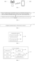
- FIG. 1 is a schematic architectural diagram of a communication system according to an embodiment of the present disclosure.
- the communication system may include, but is not limited to, a network device and a terminal, a number and form of devices shown in FIG. 1 are only used for example and do not constitute a limitation on the embodiments of the present disclosure, and the actual application may include two or more network devices, two or more terminals.
- the communications system shown in FIG. 1 includes one network device 101 and one terminal 102.
- LTE Long Term Evolution
- 5G 5th generation
- NR New Radio
- the network device 101 in the embodiments of the present disclosure is an entity for transmitting or receiving a signal on a network side.
- the network device 101 may be an evolved base station, a transmission reception point (TRP), a next generation NodeB (gNB) in an NR system, a base station in another future mobile communication system, or an access node in a wireless fidelity (WiFi) system.
- TRP transmission reception point
- gNB next generation NodeB
- WiFi wireless fidelity
- a specific technology and a specific device form used by the network device are not limited in the embodiments of the present disclosure.
- the network device provided in the embodiments of the present disclosure may be composed of a central unit (CU) and a distributed unit (DU), where the CU may also be referred to as a control unit.
- CU central unit
- DU distributed unit
- the structure of the CU-DU may split a protocol layer of the network device, for example, a base station, the function of a part of the protocol layer is centralized controlled in the CU, the function of a remaining part or all of the protocol layers is distributed in the DU, and the DU is centralized controlled by the CU.
- the terminal 102 in the embodiments of the present disclosure is an entity for receiving or transmitting a signal on a user side, for example, a mobile phone.
- the terminal may also be referred to as a terminal, user equipment (UE), a mobile station (MS), a mobile terminal (MT), or the like.
- the terminal may be a communication enabled car, a smart car, a mobile phone, a wearable device, a Pad, a computer with wireless transmission and reception capability, a virtual reality (VR) terminal, an augmented reality (AR) terminal, a wireless terminal in industrial control, a wireless terminal in autonomous driving, a wireless terminal in remote medical surgery, a wireless terminal in a smart grid, a wireless terminal in transportation safety, and a wireless terminal in a smart city, a wireless terminal in a smart home, etc.
- a specific technology and a specific device form used by the terminal are not limited in the embodiments of the present disclosure.
- the method for multi-panel enhanced transmission configuration is applicable to communication modes such as Space Division Multiplexing (SDM), Frequency Division Multiplexing (FDM), and Time Division Multiplexing (TDM).
- SDM Space Division Multiplexing
- FDM Frequency Division Multiplexing
- TDM Time Division Multiplexing
- FIG. 2 is a schematic flowchart of a method for multi-panel enhanced transmission configuration according to an embodiment of the present disclosure. The method is performed by a network device. As shown in FIG. 2 , the method may include but is not limited to the following steps.
- Step S201 at least one sounding reference signal (SRS) resource set is configured for transmission of a plurality of physical uplink shared channels (PUSCHs) that are associated with different panels, face different transmitting and receiving points (TRPs), and use different beams.
- SRS sounding reference signal
- the transmission of the plurality of PUSCHs that are associated with different panels, face different TRPs, and use different beams means that, the PUSCHs are simultaneously and respectively sent from the different panels facing different TRPs, and the different PUSCH transmission uses different beams.
- the network device configures at least one SRS resource set for the transmission of the plurality of PUSCHs, where each PUSCH transmission is PUSCH transmission from one panel facing one TRP and using a beam, and each PUSCH transmission corresponds to a panel surface, a TRP and a beam that are not completely the same.
- the PUSCHs are scheduled by a terminal with multiple panels based on a plurality of pieces of downlink control information (DCI), and are simultaneously and respectively sent from different panels, using different beams, and facing different TRPs.
- DCI downlink control information
- the transmission of the PUSCHs includes at least one of transmission of dynamic grant physical uplink shared channels (DG-PUSCHs) or transmission of configured grant physical uplink shared channels (CG-PUSCHs).
- DG-PUSCHs dynamic grant physical uplink shared channels
- CG-PUSCHs configured grant physical uplink shared channels
- the transmission of the PUSCHs includes the transmission of the DG-PUSCHs.
- the transmission of the PUSCHs includes the transmission of the CG-PUSCHs.
- the transmission of the PUSCHs includes both the transmission of the DG-PUSCHs and the transmission of the CG-PUSCHs.
- the transmission of the plurality of DG-PUSCHs associated with different panels, facing different TRPs, and using different beams is associated with corresponding SRS resource sets through control resource set pool index values of a scheduling DCI.
- transmission of each DG-PUSCH from one panel and facing one TRP is associated with one index value in the control resource set pool of the scheduling DCI, and the control resource set pool index of the scheduling DCI is associated with the SRS resource set.
- the transmission of different DG-PUSCHs corresponds to the different control resource set pool index values.
- the transmission of the different DG-PUSCHs use different beams.
- the SRS resource set associated with the control resource set pool index value can be obtained, so that the transmission of the plurality of DG-PUSCHs associated with different panels, facing different TRPs, and using different beams is associated with the corresponding SRS resource sets through the control resource set pool index values of the scheduling DCI.
- At least one SRS resource set is configured for each PUSCH.
- the PUSCH refers to a DG-PUSCH from one panel, facing one TRP, and using one beam, and different DG-PUSCHs are DG-PUSCHs from different panels, facing different TRPs, and using different beams.
- Step S202 configuration information corresponding to the at least one SRS resource set is sent to the terminal.
- the configuration information is used to indicate at least one SRS resource set and a control resource set pool index associated with at least one SRS resource set; and if a plurality of SRS resource sets are included, different SRS resource sets are associated with different control resource set pool indexes.
- the configuration information used to indicate the at least one SRS resource set and the control resource set pool index associated with the at least one SRS resource set is sent to the terminal.
- a plurality of different SRS resource sets are sent to the terminal, and the plurality of different SRS resource sets are respectively associated with the transmission of the PUSCHs from different panels, facing different TRPs, and using different beams; and the plurality of different SRS resource sets correspond to different control resource set pool indexes.
- the at least one SRS resource set includes the plurality of different SRS resource sets, and each SRS resource set is associated with the transmission of the PUSCH from one panel, facing one TRP, and using one beam; and the transmission of different PUSCHs corresponds to different control resource set pool indexes.
- a function configuration of the plurality of different SRS resource sets is a "codebook” or a “non-codebook”.
- a function configuration manner of each SRS resource set in the plurality of different SRS resource sets is a "codebook”.
- a function configuration manner of each SRS resource set in the plurality of different SRS resource sets is a "non-codebook”.
- the "codebook” means that a corresponding precoding is assigned to an available function configuration, there are a plurality of precodings, and different precodings are numbered using different sequence numbers, so that corresponding precoding may be directly searched from the table according to the sequence number, which is a codebook.
- the numbers of SRS resources included in the plurality of different SRS resource sets are separately configured. That is, each SRS resource set in the plurality of different SRS resource sets may include one or more SRS resources, and the number of SRS resources included in each SRS resource set may be the same or different.
- the plurality of different SRS resource sets are respectively associated with different power control parameters and path loss estimation reference signal (PL-RS) sets.
- PL-RS path loss estimation reference signal
- each SRS resource set in the plurality of different SRS resource sets may be associated with a corresponding power control parameter and a PL-RS set.
- the at least one SRS resource set being associated with different control resource set pool indexes includes: the plurality of different SRS resource sets are respectively associated with a plurality of different control resource set pool indexes.
- each SRS resource set in the plurality of different SRS resource sets is respectively associated with one control resource set pool index, and the different SRS resource sets are associated with different control resource set pool indexes.
- the DG-PUSCHs are associated with different SRS resource sets through the control resource set pool index values of the scheduling DCI.
- different DG-PUSCHs are respectively associated with different control resource set pool index values, and the different control resource set pool indexes are respectively associated with the different SRS resource sets. Therefore, through the control resource set pool indexes corresponds to the control resource set pool index values associated with the DG-PUSCHs, the SRS resource sets associated with the control resource set pool indexes may be obtained, implementing that the different DG-PUSCHs are associated with the different SRS resource sets.
- a CG-PUSCH may be a CG-PUSCH of a type I.
- a corresponding SRS resource set identifier and a sounding reference signal resource identifier are configured for a configured grant configuration parameter through a radio resource control (RRC) signaling, or a corresponding control resource set pool index and a corresponding SRI are configured for a configured grant configuration parameter through an RRC signaling.
- RRC radio resource control
- the CG-PUSCH of the type I is provided with an uplink grant by the RRC. All transmission parameters including a period, a time offset, a frequency resource, and a modulation and coding scheme used for uplink transmission, are configured through the RRC signaling. After receiving the RRC configuration, the terminal uses the received configured grant for transmission at the moment obtained by the preset period and offset calculation.
- the uplink transmission grant is provided by a resource management layer, and the terminal stores the configuration and uses the configuration as a grant configuration.
- the network device configures the corresponding SRS resource set identifier and the SRI for the configured grant configuration parameter through the RRC signaling.
- the network device configures the corresponding control resource set pool index and the SRI for the configured grant configuration parameter through the RRC signaling.
- a CG-PUSCH may be a CG-PUSCH of a type II.
- different configured grant configuration parameters are associated with corresponding SRS resource sets by activating the control resource set pool index values of the DCI.
- the network device associates the corresponding SRS resource sets with the different configured grant configuration parameters by activating the control resource set pool index values of the DCI.
- the CG-PUSCH of the type II is that a transmission period is provided by the RRC, and the network device implements the resource activation and the configuration of a part of the transmission parameters through DCI, so as to implement activation transmission of the grant configuration; and after receiving the activation command, the terminal transmits according to the pre-configured period if data transmission exists in the cache, and if no data exits, the terminal does not transmit any data.
- the sending time of the PDCCH specifies the activation time.
- the at least one SRS resource set includes one SRS resource set, and the one SRS resource set includes a plurality of different SRS resource subsets, in which a function configuration of the one SRS resource set is a "codebook” or a "non-codebook”.
- the at least one SRS resource set includes one SRS resource set, the SRS resource set includes the plurality of different SRS resource subsets, and a function configuration manner of the SRS resource set is a "codebook".
- the at least one SRS resource set includes one SRS resource set, the SRS resource set includes the plurality of different SRS resource subsets, and a function configuration manner of the SRS resource set is a "non-codebook".
- the SRS resource subset may be divided in a default manner. For example, a default allocation of the same numbers; the division of the SRS resource subsets may be performed in a predefined manner, for example, the SRS resource allocation is performed according to a maximum SRS port number ratio (based on the codebook) supported by different panels, or the SRS resource allocation is performed according to the same ratio of a maximum number of layers supported by different panels; or the division of the SRS resource subsets may be performed according to the configuration or indication by the base station.
- the numbers of SRS resources included in the plurality of different SRS resource subsets are separately configured.
- each SRS resource subset in the plurality of different SRS resource subsets may include one or more SRS resources, and the number of the SRS resources in each SRS resource subset may be configured separately.
- the plurality of different SRS resource subsets are respectively associated with different power control parameters and PL-RS sets.
- each SRS resource subset in the plurality of different SRS resource subsets is respectively associated with a power control parameter and a PL-RS set.
- the at least one SRS resource set being associated with different control resource set pool indexes includes: the plurality of different SRS resource subsets are associated with a plurality of different control resource set pool indexes.
- each SRS resource subset in the plurality of different SRS resource subsets is respectively associated with one control resource set pool index, and respective SRS resource subsets are associated with different control resource set pool indexes.
- the DG-PUSCHs are associated with different SRS resource subsets through the control resource set pool index values of the scheduling DCI.
- the different DG-PUSCHs are respectively associated with different control resource set pool index values, and different SRS resource subsets are respectively associated with the different control resource set pool indexes. Therefore, through the control resource set pool indexes corresponds to the control resource set pool indexes value associated with the DG-PUSCHs, the SRS resource subsets associated with the control resource set pool indexes may be obtained, to implement that different DG-PUSCHs are associated with different SRS resource subsets.
- a CG-PUSCH is a CG-PUSCH of a type I.
- a corresponding SRS resource subset identifier and an SRI are configured for a configured grant configuration parameter through an RRC signaling, or a corresponding control resource set pool index and an SRI are configured for a configured grant configuration parameter through an RRC signaling.
- the network device configures the corresponding SRS resource subset identifier and the SRI for the configured grant configuration parameter through the RRC signaling.
- the network device configures the corresponding control resource set pool index and the SRI for the configured grant configuration parameter through the RRC signaling.
- a CG-PUSCH is a CG-PUSCH of a type II.
- different configured grant configuration parameters are associated with corresponding SRS resource subsets by activating the control resource set pool index values of the DCI.
- the network device associates the corresponding SRS resource subsets with the different configured grant configuration parameters by activating the control resource set pool index values of the DCI.
- the at least one SRS resource set includes one SRS resource set, and the one SRS resource set includes a plurality of different SRS resources, in which a function configuration of the one SRS resource set is a "codebook" or a "non-codebook".
- the at least one SRS resource set includes one SRS resource set, and the one SRS resource set includes the plurality of different SRS resources; and a function configuration manner of the SRS resource set is a "codebook”.
- the at least one SRS resource set includes one SRS resource set, and the SRS resource set includes the plurality of different SRS resources; and a function configuration manner of the SRS resource set is a "non-codebook”.
- the at least one SRS resource set being associated with different control resource set pool indexes includes: the plurality of different SRS resources are associated with a plurality of different control resource set pool indexes.
- each SRS resource in the plurality of different SRS resources included in the at least one SRS resource set is respectively associated with one control resource set pool index, and respective SRS resource are associated with different control resource set pool indexes.
- the DG-PUSCHs are associated with different SRS resources through the control resource set pool index values of the scheduling DCI.
- the different DG-PUSCHs are respectively associated with the different control resource set pool index values, and the different SRS resources are respectively associated with the different control resource set pool indexes. Therefore, through the control resource set pool indexes corresponding to the control resource set pool index values associated with the DG-PUSCHs, the SRS resources associated with the control resource set pool indexes may be obtained, to implement that different DG-PUSCHs are associated with different SRS resources.
- the foregoing embodiments are implementations of the method for multi-panel enhanced transmission configuration of the embodiments of the present disclosure described from the aspect of the network device.
- the embodiments of the present disclosure further provide another method for multi-panel enhanced transmission configuration.
- the implementations of the method for multi-panel enhanced transmission configuration will be described below from the aspect of a terminal.
- the network device can configure the SRS resource set, and send the configuration information of the SRS resource set to the terminal, so that the terminal can implement independent precoding and power control based on the configuration information, thereby enhancing the uplink transmission capability of different PDCCHs.
- control resource set pool index in the embodiments of the present disclosure may be any identifier that can identify the control resource set pool, and the representation form is not limited to the examples in the foregoing embodiments.
- FIG. 3 is a schematic flowchart of another method for multi-panel enhanced transmission configuration according to an embodiment of the present disclosure.
- the method is performed by a terminal having multiple panels. As shown in FIG. 3 , the method may include but is not limited to the following steps.
- Step S301 configuration information sent by a network device is received.
- the configuration information is used to indicate at least one SRS resource set and a control resource set pool index associated with the at least one SRS resource set. If a plurality of SRS resource sets are included, different SRS resource sets are associated with different control resource set pool indexes; the at least one SRS resource set is a resource set configured by the network device for transmission of a plurality of PUSCHs associated with different panels, facing different TRPs, and using different beams. The PUSCHs are simultaneously and respectively sent from the different panels, facing different TRPs, and using different beams by the terminal based on the scheduling of a plurality of pieces of downlink control information (DCI).
- DCI downlink control information
- the terminal receives the configuration information that is sent by the network device and that is used to indicate the at least one SRS resource set and the different control resource set pool indexes associated with the SRS resource set.
- the SRS resource set is a resource set that is configured by the network device for transmission of a plurality of PUSCHs associated with different panels, facing different TRPs, and using different beams, and the PUSCHs are simultaneously and respectively sent from the different panels, facing different TRPs, and using different beams by the terminal based on the scheduling of a plurality of pieces of DCI.
- the transmission of the PUSCHs includes at least one of transmission of DG-PUSCHs or transmission of CG-PUSCHs.
- the transmission of the PUSCHs includes the transmission of the DG-PUSCHs.
- the transmission of the PUSCHs includes the transmission of the CG-PUSCHs.
- the transmission of the PUSCHs includes both the transmission of the DG-PUSCHs and the transmission of the CG-PUSCHs.
- the transmission of the plurality of DG-PUSCHs associated with different panels, facing different TRPs, and using different beams is associated with corresponding SRS resource sets through control resource set pool index values of a scheduling DCI.
- transmission of each DG-PUSCH from one panel and facing one TRP is associated with one index value in the control resource set pool of the scheduling DCI, and the control resource set pool index of the scheduling DCI is associated with the SRS resource set.
- the transmission of different DG-PUSCHs corresponds to the different control resource set pool index values.
- the transmission of the different DG-PUSCHs use different beams.
- the SRS resource set associated with the control resource set pool index value can be obtained, so that the transmission of the plurality of DG-PUSCHs associated with different panels, facing different TRPs, and using different beams is associated with the corresponding SRS resource sets through the control resource set pool index values of the scheduling DCI.
- the at least one SRS resource set includes a plurality of different SRS resource sets, and the plurality of different SRS resource sets are respectively associated with the transmission of the PUSCHs from different panels, facing different TRPs, and using different beams.
- the at least one SRS resource set includes the plurality of different SRS resource sets, and each SRS resource set is respectively associated with the transmission of the PUSCH from one panel, facing one TRP, and using one beam.
- a function configuration of the plurality of different SRS resource sets is a "codebook” or a “non-codebook”.
- a function configuration manner of each SRS resource set in the plurality of different SRS resource sets is a "codebook”.
- a function configuration manner of each SRS resource set in the plurality of different SRS resource sets is a "non-codebook”.
- the number s of SRS resources included in the plurality of different SRS resource sets are separately configured.
- each SRS resource set in the plurality of different SRS resource sets may include one or more SRS resources, and the number of SRS resources included in each SRS resource set may be configured separately. That is, each SRS resource set in the plurality of different SRS resource sets may include one or more SRS resources, and the number of SRS resources included in each SRS resource set may be the same or different.
- the plurality of different SRS resource sets are respectively associated with different power control parameters and PL-RS sets.
- each SRS resource set in the plurality of different SRS resource sets may be associated with a corresponding power control parameter and a PL-RS set.
- the at least one SRS resource set being associated with different control resource set pool indexes includes: the plurality of different SRS resource sets are respectively associated with a plurality of different control resource set pool indexes.
- each SRS resource set in the plurality of different SRS resource sets is respectively associated with one control resource set pool index, and the different SRS resource sets are associated with different control resource set pool indexes.
- the DG-PUSCHs are associated with different SRS resource sets through the control resource set pool index values of the scheduling DCI.
- different DG-PUSCHs are respectively associated with different control resource set pool index values, and the different control resource set pool indexes are respectively associated with the different SRS resource sets. Therefore, through the control resource set pool indexes corresponds to the control resource set pool index values associated with the DG-PUSCHs, the SRS resource sets associated with the control resource set pool indexes may be obtained, implementing that the different DG-PUSCHs are associated with the different SRS resource sets.
- a CG-PUSCH may be a CG-PUSCH of a type I.
- a corresponding SRS resource set identifier and an SRI are configured for a configured grant configuration parameter through an RRC signaling, or a corresponding control resource set pool index and a corresponding SRI are configured for a configured grant configuration parameter through an RRC signaling
- the terminal configures the corresponding SRS resource set identifier and the SRI for the configured grant configuration parameter through the RRC signaling.
- the terminal configures the corresponding control resource set pool index and the SRI for the configured grant configuration parameter through the RRC signaling.
- a CG-PUSCH may be a CG-PUSCH of a type II.
- different configured grant configuration parameters are associated with corresponding SRS resource sets by activating the control resource set pool index values of the DCI.
- the terminal associates the corresponding SRS resource sets with the different configured grant configuration parameters by activating the control resource set pool index values of the DCI.
- the at least one SRS resource set includes one SRS resource set, and the one SRS resource set includes a plurality of different SRS resource subsets, in which a function configuration of the one SRS resource set is a "codebook” or a "non-codebook”.
- the at least one SRS resource set includes one SRS resource set, the SRS resource set includes the plurality of different SRS resource subsets, and a function configuration manner of the SRS resource set is a "codebook".
- the at least one SRS resource set includes one SRS resource set, the SRS resource set includes the plurality of different SRS resource subsets, and a function configuration manner of the SRS resource set is a "non-codebook".
- the numbers of SRS resources included in the plurality of different SRS resource subsets are separately configured.
- each SRS resource subset in the plurality of different SRS resource subsets may include one or more SRS resources, and the number of the SRS resources in each SRS resource subset may be configured separately.
- the plurality of different SRS resource subsets are respectively associated with different power control parameters and PL-RS sets.
- each SRS resource subset in the plurality of different SRS resource subsets is respectively associated with a power control parameter and a PL-RS set.
- the at least one SRS resource set being associated with different control resource set pool indexes includes: the plurality of different SRS resource subsets are associated with a plurality of different control resource set pool indexes.
- each SRS resource subset in the plurality of different SRS resource subsets is respectively associated with one control resource set pool index, and respective SRS resource subsets are associated with different control resource set pool indexes.
- the DG-PUSCHs are associated with different SRS resource subsets through the control resource set pool index values of the scheduling DCI.
- the different DG-PUSCHs are respectively associated with different control resource set pool index values, and different SRS resource subsets are respectively associated with the different control resource set pool indexes. Therefore, through the control resource set pool indexes corresponds to the control resource set pool indexes value associated with the DG-PUSCHs, the SRS resource subsets associated with the control resource set pool indexes may be obtained, to implement that different DG-PUSCHs are associated with different SRS resource subsets.
- a CG-PUSCH is a CG-PUSCH of a type I.
- a corresponding SRS resource subset identifier and an SRI are configured for a configured grant configuration parameter through an RRC signaling, or a corresponding control resource set pool index and an SRI are configured for a configured grant configuration parameter through an RRC signaling.
- the terminal configures the corresponding SRS resource subset identifier and the SRI for the configured grant configuration parameter through the RRC signaling.
- the terminal configures the corresponding control resource set pool index and the SRI for the configured grant configuration parameter through the RRC signaling.
- a CG-PUSCH is a CG-PUSCH of a type II.
- different configured grant configuration parameters are associated with corresponding SRS resource subsets by activating the control resource set pool index values of the DCI.
- the network device associates the corresponding SRS resource subsets with the different configured grant configuration parameters by activating the control resource set pool index values of the DCI.
- the at least one SRS resource set includes one SRS resource set, and the one SRS resource set includes a plurality of different SRS resources, in which a function configuration of the one SRS resource set is a "codebook” or a "non-codebook”.
- the at least one SRS resource set includes one SRS resource set, and the one SRS resource set includes the plurality of different SRS resources; and a function configuration manner of the SRS resource set is a "codebook".
- the at least one SRS resource set includes one SRS resource set, and the SRS resource set includes the plurality of different SRS resources; and a function configuration manner of the SRS resource set is a "non-codebook".
- the at least one SRS resource set being associated with different control resource set pool indexes includes: the plurality of different SRS resources are associated with a plurality of different control resource set pool indexes.
- each SRS resource in the plurality of different SRS resources included in the at least one SRS resource set is respectively associated with one control resource set pool index, and different SRS resource are associated with different control resource set pool indexes.
- the DG-PUSCHs are associated with different SRS resources through the control resource set pool index values of the scheduling DCI.
- the different DG-PUSCHs are respectively associated with the different control resource set pool index values, and the different SRS resources are respectively associated with the different control resource set pool indexes. Therefore, through the control resource set pool indexes corresponding to the control resource set pool index values associated with the DG-PUSCHs, the SRS resources associated with the control resource set pool indexes may be obtained, to implement that different DG-PUSCHs are associated with different SRS resources.
- a CG-PUSCH is a CG-PUSCH of a type I.
- a corresponding SRS resource identifier and an SRI are configured for the configured grant configuration parameter through an RRC signaling, or a corresponding control resource set pool index and an SRI are configured for the configured grant configuration parameter through an RRC signaling.
- the terminal configures the corresponding SRS resource identifier and the SRI for the configured grant configuration parameter through the RRC signaling.
- the terminal configures the corresponding control resource set pool index and the SRI for the configured grant configuration parameter through the RRC signaling.
- a CG-PUSCH is a CG-PUSCH of a type II.
- different configured grant configuration parameters are associated with corresponding SRS resources by activating the control resource set pool index values of the DCI.
- the terminal associates corresponding SRS resources with different configured grant configuration parameters by activating the control resource set pool index values of the DCI.
- the terminal can receive the configuration information of the SRS resource set sent by the network device, and implement independent precoding and power control based on the configuration information, thereby enhancing the uplink transmission capability of different PDCCHs.
- FIG. 4 is a schematic structural diagram of a communication apparatus 40 according to an embodiment of the present disclosure.
- the communication apparatus 40 shown in FIG. 4 may include a transceiver module 401 and a processing module 402.
- the transceiver module 401 may include a sending module and/or a transceiver module, the sending module is configured to implement a sending function, and the transceiver module is configured to implement a receiving function, and the transceiver module 401 may implement a sending function and/or a receiving function.
- the communication apparatus 40 may be a network device, an apparatus in the network device, or may be an apparatus that can be used by matching with the network device; or the communication apparatus 40 may be a terminal, an apparatus in the terminal, or an apparatus that can be used by matching with the terminal.
- a processing module 402 is configured to configure at least one sounding reference signal (SRS) resource set for transmission of a plurality of physical uplink shared channels (PUSCHs) that are associated with different panels, face different transmitting and receiving points (TRPs), and use different beams; in which the PUSCHs are PUSCHs simultaneously and respectively sent from different panels, using different beams, and facing different TRPs by a terminal having multiple panels based on scheduling of a plurality of pieces of downlink control information (DCI); and a transceiver module 401 is configured to send configuration information corresponding to the at least one SRS resource set to the terminal, in which the configuration information is used to indicate the at least one SRS resource set, and indicate that the at least one SRS resource set is associated with different control resource set pool indexes.
- SRS sounding reference signal
- the transmission of the PUSCHs includes at least one of transmission of dynamic grant physical uplink shared channels (DG-PUSCHs) or transmission of configured grant physical uplink shared channels (CG-PUSCHs).
- DG-PUSCHs dynamic grant physical uplink shared channels
- CG-PUSCHs configured grant physical uplink shared channels
- the transmission of DG-PUSCHs associated with different panels, facing different TRPs, and using different beams is associated with corresponding SRS resource sets through control resource set pool index values of a scheduling DCI.
- the at least one SRS resource set includes a plurality of different SRS resource sets, and the plurality of different SRS resource sets are respectively associated with transmission of different PUSCHs from different panels, facing different TRPs, and using different beams; and a function configuration of the plurality of different SRS resource sets is a "codebook” or a "non-codebook”.
- the numbers of SRS resources included in the plurality of different SRS resource sets are separately configured.
- the plurality of different SRS resource sets are respectively associated with different power control parameters and path loss estimation reference signal (PL - RS) sets.
- PL - RS path loss estimation reference signal
- the at least one SRS resource set being associated with different control resource set pool indexes includes: the plurality of different SRS resource sets are respectively associated with a plurality of different control resource set pool indexes.
- the DG-PUSCHs are associated with different SRS resource sets through the control resource set pool index values of the scheduling DCI.
- a CG-PUSCH is a CG-PUSCH of a type I; in which for the CG-PUSCH of the type I, a corresponding SRS resource set identifier and a sounding reference signal resource indication (SRI) are configured for a configured grant configuration parameter through a radio resource control (RRC) signaling, or a corresponding control resource set pool index and an SRI are configured for a configured grant configuration parameter through an RRC signaling.
- RRC radio resource control
- a CG-PUSCH is a CG-PUSCH of a type II; in which for the CG-PUSCH of the type II, different configured grant configuration parameters are associated with corresponding SRS resource sets by activating the control resource set pool index values of the DCI.
- the at least one SRS resource set includes one SRS resource set, and the one SRS resource set includes a plurality of different SRS resource subsets, in which a function configuration of the one SRS resource set is a "codebook” or a "non-codebook”.
- the numbers of SRS resources included in the plurality of different SRS resource subsets are separately configured.
- the plurality of different SRS resource subsets are respectively associated with different power control parameters and PL-RS sets.
- the at least one SRS resource set being associated with different control resource set pool indexes includes: the plurality of different SRS resource subsets are associated with a plurality of different control resource set pool indexes.
- the DG-PUSCHs are associated with different SRS resource subsets through the control resource set pool index values of the scheduling DCI.
- a CG-PUSCH is a CG-PUSCH of a type I; in which for the CG-PUSCH of the type I, a corresponding SRS resource subset identifier and an SRI are configured for a configured grant configuration parameter through an RRC signaling, or a corresponding control resource set pool index and an SRI are configured for a configured grant configuration parameter through an RRC signaling.
- a CG-PUSCH is a CG-PUSCH of a type II; in which for the CG-PUSCH of the type II, different configured grant configuration parameters are associated with corresponding SRS resource subsets by activating the control resource set pool index values of the DCI.
- the at least one SRS resource set includes one SRS resource set, and the one SRS resource set includes a plurality of different SRS resources, in which a function configuration of the one SRS resource set is a "codebook” or a "non-codebook”.
- the at least one SRS resource set being associated with different control resource set pool indexes includes the plurality of different SRS resources are associated with a plurality of different control resource set pool indexes.
- the DG-PUSCHs are associated with different SRS resources through the control resource set pool index values of the scheduling DCI.
- a CG-PUSCH is a CG-PUSCH of a type I; in which for the CG-PUSCH of the type I, a corresponding SRS resource identifier and an SRI are configured for a configured grant configuration parameter through an RRC signaling, or a corresponding control resource set pool index and an SRI are configured for a configured grant configuration parameter through an RRC signaling.
- a CG-PUSCH is a CG-PUSCH of a type II; in which for the CG-PUSCH of the type II, different configured grant configuration parameters are associated with corresponding SRS resources by activating the control resource set pool index values of the DCI.
- the network device can configure the SRS resource set, and send the configuration information of the SRS resource set to the terminal, so that the terminal can implement independent precoding and power control based on the configuration information, thereby enhancing the uplink transmission capability of different PDCCHs.
- a transceiver module 401 is configured to receive configuration information sent by a network device, in which the configuration information is used to indicate at least one SRS resource set, and indicate that the at least one SRS resource set is associated with different control resource set pool indexes.
- the at least one SRS resource set is a resource set configured by the network device for transmission of a plurality of physical uplink shared channels (PUSCHs) that are associated with different panels, face different transmitting and receiving points (TRPs), and use different beams, and the PUSCHs are PUSCHs simultaneously and respectively sent from different panels, using different beams, and facing different TRPs by the terminal based on scheduling of a plurality of pieces of downlink control information (DCI).
- DCI downlink control information
- the transmission of the PUSCHs includes at least one of transmission of dynamic grant physical uplink shared channels (DG-PUSCHs) or transmission of configured grant physical uplink shared channels (CG-PUSCHs).
- DG-PUSCHs dynamic grant physical uplink shared channels
- CG-PUSCHs configured grant physical uplink shared channels
- the transmission of DG-PUSCHs associated with different panels, facing different TRPs, and using different beams is associated with corresponding SRS resource sets through control resource set pool index values of a scheduling DCI.
- the at least one SRS resource set includes a plurality of different SRS resource sets, and the plurality of different SRS resource sets are respectively associated with transmission of different PUSCHs from different panels, facing different TRPs, and using different beams; and a function configuration of the plurality of different SRS resource sets is a "codebook” or a "non-codebook”.
- the numbers of SRS resources included in the plurality of different SRS resource sets are separately configured.
- the plurality of different SRS resource sets are respectively associated with different power control parameters and path loss estimation reference signal (PL - RS) sets.
- PL - RS path loss estimation reference signal
- the at least one SRS resource set being associated with different control resource set pool indexes includes: the plurality of different SRS resource sets are respectively associated with a plurality of different control resource set pool indexes.
- the DG-PUSCHs are associated with different SRS resource sets through the control resource set pool index values of the scheduling DCI.
- a CG-PUSCH is a CG-PUSCH of a type I; in which for the CG-PUSCH of the type I, a corresponding SRS resource set identifier and a sounding reference signal resource indication (SRI) are configured for a configured grant configuration parameter through a radio resource control (RRC) signaling, or a corresponding control resource set pool index and an SRI are configured for a configured grant configuration parameter through an RRC signaling.
- RRC radio resource control
- a CG-PUSCH is a CG-PUSCH of a type II; in which for the CG-PUSCH of the type II, different configured grant configuration parameters are associated with corresponding SRS resource sets by activating the control resource set pool index values of the DCI.
- the at least one SRS resource set includes one SRS resource set, and the one SRS resource set includes a plurality of different SRS resources, in which a function configuration of the one SRS resource set is a "codebook” or a "non-codebook”.
- the numbers of SRS resources included in the plurality of different SRS resource subsets are separately configured.
- the plurality of different SRS resource subsets are respectively associated with different power control parameters and PL-RS sets.
- the at least one SRS resource set being associated with different control resource set pool indexes includes: the plurality of different SRS resource subsets are associated with a plurality of different control resource set pool indexes.
- the DG-PUSCHs are associated with different SRS resource subsets through the control resource set pool index values of the scheduling DCI.
- a CG-PUSCH is a CG-PUSCH of a type I; in which for the CG-PUSCH of the type I, a corresponding SRS resource subset identifier and an SRI are configured for a configured grant configuration parameter through an RRC signaling, or a corresponding control resource set pool index and an SRI are configured for a configured grant configuration parameter through an RRC signaling.
- a CG-PUSCH is a CG-PUSCH of a type II; in which for the CG-PUSCH of the type II, different configured grant configuration parameters are associated with corresponding SRS resource subsets by activating the control resource set pool index values of the DCI.
- the at least one SRS resource set includes one SRS resource set, and the one SRS resource set includes a plurality of different SRS resources, in which a function configuration of the one SRS resource set is a "codebook” or a "non-codebook”.
- the at least one SRS resource set being associated with different control resource set pool indexes includes: the plurality of different SRS resources are associated with a plurality of different control resource set pool indexes.
- the DG-PUSCHs are associated with different SRS resources through the control resource set pool index value of the scheduling DC.
- a CG-PUSCH is a CG-PUSCH of a type I; in which for the CG-PUSCH of the type I, a corresponding SRS resource identifier and an SRI are configured for a configured grant configuration parameter through an RRC signaling, or a corresponding control resource set pool index and an SRI are configured for a configured grant configuration parameter through an RRC signaling.
- a CG-PUSCH is a CG-PUSCH of a type II; in which for the CG-PUSCH of the type II, different configured grant configuration parameters are associated with corresponding SRS resources by activating the control resource set pool index values of the DCI.
- the terminal can receive the configuration information of the SRS resource set sent by the network device, and implement independent precoding and power control based on the configuration information, thereby enhancing the uplink transmission capability of different PDCCHs.
- FIG. 5 is a block diagram of another communication apparatus 50 according to an embodiment of the present disclosure.
- the communication apparatus 50 may be a network device, a terminal, or a chip, a chip system, or a processor, etc., that supports the network device to realize the above methods, or a chip, a chip system, or a processor, etc., that supports the terminal to realize the above methods.
- the apparatus can be used to realize the methods in the method embodiments. For details, please refer to the description in the method embodiments.
- the communication apparatus 50 may include one or more processors 501.
- the processor 501 can be a general-purpose processor or a special-purpose processor, for example, a baseband processor or a central processing unit.
- the baseband processor can be used to process the communication protocol and communication data
- the central processing unit can be used to control the communication apparatus (such as a base station, a baseband chip, a terminal, a terminal chip, a DU or CU, etc.), execute the computer program, and process the data of the computer program.
- the communication apparatus 50 may also include one or more memories 502 for storing a computer program 503.
- the communication apparatus 50 is caused to perform the methods in the above method embodiments.
- data may also be stored in the memory 502.
- the communication apparatus 50 and the memory 502 can be separate or integrated.
- the communication apparatus 50 may also include a transceiver 504, and an antenna 505.
- the transceiver 504 can be called a transceiver unit, a transceiving machine, or a transceiver circuit, etc., to realize the transmitting and receiving function.
- the transceiver 504 may include a receiver and a transmitter.
- the receiver may be called a receiving machine or a receiving circuit, etc., to realize the receiving function
- the transmitter can be called a transmitting machine or a transmitting circuit, etc., to realize the transmitting function.
- the communication apparatus 50 may also include one or more interface circuits 5010.
- the interface circuit 5010 is configured to receive code instructions and transmit the code instructions to the processor 501.
- the processor 501 runs code instructions to cause the communication apparatus 50 to perform the methods in the above method embodiments.
- the transceiver 504 is configured to perform the step S202 in Fig. 2
- the processor 501 is configured to perform the step S201 in Fig. 2 .
- the transceiver 504 is configured to perform the step S301 in Fig. 3 .
- the processor 501 may include a transceiver for implementing receiving and transmitting function.
- the transceiver can be a transceiver circuit, or an interface, or an interface circuit.
- the transceiver circuit, interface, or interface circuit used to implement the receiving and transmitting function can be separate or integrated.
- the transceiver circuit, interface, or interface circuit may be used for reading and writing code/data, or the transceiver circuit, interface, or interface circuit may be used for the transmission or transfer of signals.
- a computer program may be stored on the processor 501.
- the communication apparatus 50 is caused to perform the methods in the above method embodiments.
- the computer program may be solidified in the processor 501.
- the processor 501 may be implemented by a hardware.
- the communication apparatus 50 includes a circuit that can implement the sending or receiving or communicating function in the above method embodiments.
- the processor and transceiver in the present disclosure can be implemented in an integrated circuit (IC), an analog IC, a radio frequency integrated circuit (RFIC), a mixed-signal IC, an application specific integrated circuit (ASIC), a printed circuit board (PCB), an electronic device, etc.
- the processor and transceiver can also be manufactured with various IC process technologies, such as a complementary metal oxide semiconductor (CMOS), nMetal-oxide-semiconductor (NMOS), a positive channel metal oxide semiconductor (PMOS), a bipolar junction transistor (BJT), a bipolar CMOS (BiCMOS), silicon germanium (SiGe), gallium arsenide (GaAs), etc.
- CMOS complementary metal oxide semiconductor
- NMOS nMetal-oxide-semiconductor
- PMOS positive channel metal oxide semiconductor
- BJT bipolar junction transistor
- BiCMOS bipolar CMOS
- SiGe silicon germanium
- GaAs gallium arsenide
- the communication apparatus in the above embodiments may be a network device or a terminal (such as the terminal in the method embodiments), but the scope of the communication apparatus in the present disclosure is not limited to this, and the structure of the communication apparatus may not be limited by FIG. 10.
- the communication apparatus can be an independent device or part of a larger device.
- the communication apparatus may be:
- the communication apparatus may be a chip or a chip system
- the chip shown in FIG. 6 includes a processor 601 and an interface 602, in which there may be one or more processors 601, and there may be a plurality of interfaces 602.
- the processor 601 is configured to configure at least one sounding reference signal (SRS) resource set for transmission of a plurality of physical uplink shared channels (PUSCHs) that are associated with different panels, face different transmitting and receiving points (TRPs), and use different beams; in which the PUSCHs are PUSCHs simultaneously and respectively sent from different panels, using different beams, and facing different TRPs by a terminal having multiple panels based on scheduling of a plurality of pieces of downlink control information (DCI); and the interface 602 is configured to send configuration information corresponding to the at least one SRS resource set to the terminal, in which the configuration information is used to indicate the at least one SRS resource set, and indicate that the at least one SRS resource set is associated with different control resource set pool indexes.
- SRS sounding reference signal
- the transmission of the PUSCHs includes at least one of transmission of dynamic grant physical uplink shared channels (DG-PUSCHs) or transmission of configured grant physical uplink shared channels (CG-PUSCHs).
- DG-PUSCHs dynamic grant physical uplink shared channels
- CG-PUSCHs configured grant physical uplink shared channels
- the transmission of DG-PUSCHs associated with different panels, facing different TRPs, and using different beams is associated with corresponding SRS resource sets through control resource set pool index values of a scheduling DCI.
- the at least one SRS resource set includes a plurality of different SRS resource sets, and the plurality of different SRS resource sets are respectively associated with transmission of different PUSCHs from different panels, facing different TRPs, and using different beams; and a function configuration of the plurality of different SRS resource sets is a "codebook” or a "non-codebook”.
- the numbers of SRS resources included in the plurality of different SRS resource sets are separately configured.
- the plurality of different SRS resource sets are respectively associated with different power control parameters and path loss estimation reference signal (PL-RS) sets.
- PL-RS path loss estimation reference signal
- the at least one SRS resource set being associated with different control resource set pool indexes includes: the plurality of different SRS resource sets are respectively associated with a plurality of different control resource set pool indexes.
- the DG-PUSCHs are associated with different SRS resource sets through the control resource set pool index values of the scheduling DCI.
- a CG-PUSCH is a CG-PUSCH of a type I; in which for the CG-PUSCH of the type I, a corresponding SRS resource set identifier and a sounding reference signal resource indication (SRI) are configured for a configured grant configuration parameter through a radio resource control (RRC) signaling, or a corresponding control resource set pool index and an SRI are configured for a configured grant configuration parameter through an RRC signaling.
- RRC radio resource control
- a CG-PUSCH is a CG-PUSCH of a type II; in which for the CG-PUSCH of the type II, different configured grant configuration parameters are associated with corresponding SRS resource sets by activating the control resource set pool index values of the DCI.
- the at least one SRS resource set includes one SRS resource set, and the one SRS resource set includes a plurality of different SRS resource subsets, in which a function configuration of the one SRS resource set is a "codebook” or a "non-codebook”.
- the numbers of SRS resources included in the plurality of different SRS resource subsets are separately configured.
- the plurality of different SRS resource subsets are respectively associated with different power control parameters and PL-RS sets.
- the at least one SRS resource set being associated with different control resource set pool indexes includes: the plurality of different SRS resource subsets are associated with a plurality of different control resource set pool indexes.
- the DG-PUSCHs are associated with different SRS resource subsets through the control resource set pool index values of the scheduling DCI.
- a CG-PUSCH is a CG-PUSCH of a type I; in which for the CG-PUSCH of the type I, a corresponding SRS resource subset identifier and an SRI are configured for a configured grant configuration parameter through an RRC signaling, or a corresponding control resource set pool index and an SRI are configured for a configured grant configuration parameter through an RRC signaling.
- a CG-PUSCH is a CG-PUSCH of a type II; in which for the CG-PUSCH of the type II, different configured grant configuration parameters are associated with corresponding SRS resource subsets by activating the control resource set pool index values of the DCI.
- the at least one SRS resource set includes one SRS resource set, and the one SRS resource set includes a plurality of different SRS resources, in which a function configuration of the one SRS resource set is a "codebook” or a "non-codebook”.
- the at least one SRS resource set being associated with different control resource set pool indexes includes the plurality of different SRS resources are associated with a plurality of different control resource set pool indexes.
- the DG-PUSCHs are associated with different SRS resources through the control resource set pool index values of the scheduling DCI.
- a CG-PUSCH is a CG-PUSCH of a type I; in which for the CG-PUSCH of the type I, a corresponding SRS resource identifier and an SRI are configured for a configured grant configuration parameter through an RRC signaling, or a corresponding control resource set pool index and an SRI are configured for a configured grant configuration parameter through an RRC signaling.
- a CG-PUSCH is a CG-PUSCH of a type II; in which for the CG-PUSCH of the type II, different configured grant configuration parameters are associated with corresponding SRS resources by activating the control resource set pool index values of the DCI.
- the interface 602 is configured to receive configuration information sent by a network device, in which the configuration information is used to indicate at least one SRS resource set, and indicate that the at least one SRS resource set is associated with different control resource set pool indexes.
- the at least one SRS resource set is a resource set configured by the network device for transmission of a plurality of physical uplink shared channels (PUSCHs) that are associated with different panels, face different transmitting and receiving points (TRPs), and use different beams, and the PUSCHs are PUSCHs simultaneously and respectively sent from different panels, using different beams, and facing different TRPs by the terminal based on scheduling of a plurality of pieces of downlink control information (DCI).
- PUSCHs physical uplink shared channels
- TRPs transmitting and receiving points
- the transmission of the PUSCHs includes at least one of transmission of dynamic grant physical uplink shared channels (DG-PUSCHs) or transmission of configured grant physical uplink shared channels (CG-PUSCHs).
- DG-PUSCHs dynamic grant physical uplink shared channels
- CG-PUSCHs configured grant physical uplink shared channels
- the transmission of DG-PUSCHs associated with different panels, facing different TRPs, and using different beams is associated with corresponding SRS resource sets through control resource set pool index values of a scheduling DCI.
- the at least one SRS resource set includes a plurality of different SRS resource sets, and the plurality of different SRS resource sets are respectively associated with transmission of different PUSCHs from different panels, facing different TRPs, and using different beams; and a function configuration of the plurality of different SRS resource sets is a "codebook” or a "non-codebook”.
- the numbers of SRS resources included in the plurality of different SRS resource sets are separately configured.
- the plurality of different SRS resource sets are respectively associated with different power control parameters and path loss estimation reference signal (PL - RS) sets.
- PL - RS path loss estimation reference signal
- the at least one SRS resource set being associated with different control resource set pool indexes includes: the plurality of different SRS resource sets are respectively associated with a plurality of different control resource set pool indexes.
- the DG-PUSCHs are associated with different SRS resource sets through the control resource set pool index values of the scheduling DCI.
- a CG-PUSCH is a CG-PUSCH of a type I; in which for the CG-PUSCH of the type I, a corresponding SRS resource set identifier and a sounding reference signal resource indication (SRI) are configured for a configured grant configuration parameter through a radio resource control (RRC) signaling, or a corresponding control resource set pool index and an SRI are configured for a configured grant configuration parameter through an RRC signaling.
- RRC radio resource control
- a CG-PUSCH is a CG-PUSCH of a type II; in which for the CG-PUSCH of the type II, different configured grant configuration parameters are associated with corresponding SRS resource sets by activating the control resource set pool index values of the DCI.
- the at least one SRS resource set includes one SRS resource set, and the one SRS resource set includes a plurality of different SRS resources, in which a function configuration of the one SRS resource set is a "codebook” or a "non-codebook”.
- the numbers of SRS resources included in the plurality of different SRS resource subsets are separately configured.
- the plurality of different SRS resource subsets are respectively associated with different power control parameters and PL-RS sets.
- the at least one SRS resource set being associated with different control resource set pool indexes includes: the plurality of different SRS resource subsets are associated with a plurality of different control resource set pool indexes.
- the DG-PUSCHs are associated with different SRS resource subsets through the control resource set pool index values of the scheduling DCI.
- a CG-PUSCH is a CG-PUSCH of a type I; in which for the CG-PUSCH of the type I, a corresponding SRS resource subset identifier and an SRI are configured for a configured grant configuration parameter through an RRC signaling, or a corresponding control resource set pool index and an SRI are configured for a configured grant configuration parameter through an RRC signaling.
- a CG-PUSCH is a CG-PUSCH of a type II; in which for the CG-PUSCH of the type II, different configured grant configuration parameters are associated with corresponding SRS resource subsets by activating the control resource set pool index values of the DCI.
- the at least one SRS resource set includes one SRS resource set, and the one SRS resource set includes a plurality of different SRS resources, in which a function configuration of the one SRS resource set is a "codebook” or a "non-codebook”.
- the at least one SRS resource set being associated with different control resource set pool indexes includes: the plurality of different SRS resources are associated with a plurality of different control resource set pool indexes.
- the DG-PUSCHs are associated with different SRS resources through the control resource set pool index value of the scheduling DC.
- a CG-PUSCH is a CG-PUSCH of a type I; in which for the CG-PUSCH of the type I, a corresponding SRS resource identifier and an SRI are configured for a configured grant configuration parameter through an RRC signaling, or a corresponding control resource set pool index and an SRI are configured for a configured grant configuration parameter through an RRC signaling.
- a CG-PUSCH is a CG-PUSCH of a type II; in which for the CG-PUSCH of the type II, different configured grant configuration parameters are associated with corresponding SRS resources by activating the control resource set pool index values of the DCI.
- the chip further includes a memory 603, and the memory 603 is configured to store necessary computer programs and data.
- the embodiments of the present disclosure further provide a system for multi-panel enhanced transmission configuration, which includes a communication apparatus serving as a terminal in the foregoing embodiments in FIG. 4 and a communication apparatus serving as a network device, or the system includes a communication apparatus serving as a terminal in the foregoing embodiments in FIG. 5 and a communication apparatus serving as a network device.
- the present disclosure further provides a readable storage medium having stored thereon instructions that, when executed by a computer, implement the functions of any one of the above method embodiments.
- the present disclosure further provides a computer program product, which, when executed by a computer, implements the functions of any one of the above method embodiments.
- the functions may be wholly or partially implemented by software, hardware, firmware, or any combination of them.
- the functions When implemented by software, the functions may be implemented in whole or in part in the form of a computer program product.
- the computer program product includes one or more computer programs. Procedures or functions according to embodiments of the present disclosure are wholly or partially generated when the computer program is loaded and executed on a computer.
- the computer may be a general purpose computer, a special purpose computer, a computer network, or other programmable device.
- the computer program may be stored in a computer-readable storage medium or transmitted from one computer-readable storage medium to another.
- the computer program may be transmitted from one website, computer, server, or data center to another website, computer, server, or data center via wire (such as a coaxial cable, a fiber optic, a digital subscriber line (DSL)) or wireless (such as infrared, wireless, microwave).
- the computer-readable storage medium may be any available medium that may be accessed by a computer, or a data storage device such as a server that integrates one or more of the available media, and a data center.
- the available medium media be a magnetic medium (such as a floppy disk, a hard disk and a magnetic tape), an optical medium (such as a digital video disk (DVD)), or a semiconductor medium (such as a solid state disk (SSD)).
- the term “at least one” in the present disclosure may also be described as one or more, and the more may be two, three, four, or more, which is not limited in the present disclosure.
- the technical feature in the technical features are distinguished by terms “first”, “second”, “third”, “A”, “B”, “C” and “D”, etc., and the technical features described by the terms “first”, “second”, “third”, “A”, “B”, “C” and “D”, etc. are not in a sequential order or in an order of size.
- predefined in the present disclosure may be understood as definition, pre-definition, storage, pre-storage, pre-negotiation, pre-configuration, curing, or pre-firing.
Landscapes
- Engineering & Computer Science (AREA)
- Signal Processing (AREA)
- Computer Networks & Wireless Communication (AREA)
- Mobile Radio Communication Systems (AREA)
Applications Claiming Priority (1)
| Application Number | Priority Date | Filing Date | Title |
|---|---|---|---|
| PCT/CN2022/106583 WO2024016186A1 (fr) | 2022-07-19 | 2022-07-19 | Procédé de configuration de transmission améliorée par panneaux multiples et appareil associé |
Publications (2)
| Publication Number | Publication Date |
|---|---|
| EP4560955A1 true EP4560955A1 (fr) | 2025-05-28 |
| EP4560955A4 EP4560955A4 (fr) | 2025-08-06 |
Family
ID=89616740
Family Applications (1)
| Application Number | Title | Priority Date | Filing Date |
|---|---|---|---|
| EP22951464.1A Pending EP4560955A4 (fr) | 2022-07-19 | 2022-07-19 | Procédé de configuration de transmission améliorée par panneaux multiples et appareil associé |
Country Status (4)
| Country | Link |
|---|---|
| US (1) | US20260031948A1 (fr) |
| EP (1) | EP4560955A4 (fr) |
| CN (2) | CN121150893A (fr) |
| WO (1) | WO2024016186A1 (fr) |
Families Citing this family (1)
| Publication number | Priority date | Publication date | Assignee | Title |
|---|---|---|---|---|
| WO2025208575A1 (fr) * | 2024-04-04 | 2025-10-09 | 北京小米移动软件有限公司 | Procédé de commande de puissance et appareil et dispositif de communication |
Family Cites Families (8)
| Publication number | Priority date | Publication date | Assignee | Title |
|---|---|---|---|---|
| JP2019103057A (ja) * | 2017-12-06 | 2019-06-24 | シャープ株式会社 | 端末装置、基地局装置および通信方法 |
| TWI710227B (zh) * | 2018-08-17 | 2020-11-11 | 美商Idac控股公司 | 多trp之波束管理 |
| WO2020155179A1 (fr) * | 2019-02-03 | 2020-08-06 | Oppo广东移动通信有限公司 | Procédé de transmission de signal, dispositif terminal et dispositif de réseau |
| US11589382B2 (en) * | 2019-10-11 | 2023-02-21 | Qualcomm Incorporated | Default transmission beams for multiple transmission-reception points in wireless communications |
| WO2021163990A1 (fr) * | 2020-02-21 | 2021-08-26 | Oppo广东移动通信有限公司 | Procédé et appareil de commande de transmission de liaison montante, et dispositif associé |
| JP7496885B2 (ja) * | 2020-03-16 | 2024-06-07 | エルジー エレクトロニクス インコーポレイティド | 無線通信システムにおいてpusch送受信方法及び装置 |
| WO2022082372A1 (fr) * | 2020-10-19 | 2022-04-28 | 北京小米移动软件有限公司 | Procédé et appareil d'indication de pusch, et procédé et appareil d'envoi de pusch |
| WO2022085155A1 (fr) * | 2020-10-22 | 2022-04-28 | 株式会社Nttドコモ | Terminal, procédé de communication radio et station de base |
-
2022
- 2022-07-19 CN CN202511158879.7A patent/CN121150893A/zh active Pending
- 2022-07-19 US US18/995,079 patent/US20260031948A1/en active Pending
- 2022-07-19 CN CN202280002565.6A patent/CN117730504B/zh active Active
- 2022-07-19 EP EP22951464.1A patent/EP4560955A4/fr active Pending
- 2022-07-19 WO PCT/CN2022/106583 patent/WO2024016186A1/fr not_active Ceased
Also Published As
| Publication number | Publication date |
|---|---|
| CN121150893A (zh) | 2025-12-16 |
| US20260031948A1 (en) | 2026-01-29 |
| EP4560955A4 (fr) | 2025-08-06 |
| CN117730504A (zh) | 2024-03-19 |
| CN117730504B (zh) | 2025-09-02 |
| WO2024016186A1 (fr) | 2024-01-25 |
Similar Documents
| Publication | Publication Date | Title |
|---|---|---|
| EP4518201A1 (fr) | Procédé et dispositif de détermination d'état d'indication de configuration | |
| US20240340989A1 (en) | Transmission configuration indicator (tci) state configuration method and apparatus | |
| EP4518202A1 (fr) | Procédé de détermination d'état d'indication de configuration de transmission et appareil | |
| EP4322648A1 (fr) | Procédé et appareil d'attribution de ressources dans le domaine temporel | |
| CN115299007A (zh) | 一种传输配置指示tci状态使用时间的确定方法及其装置 | |
| EP4694435A1 (fr) | Procédé de configuration pour signal de référence et appareil | |
| EP4492703A1 (fr) | Procédé de rapport de capacité de commutation d'antenne et appareil faisant appel à celui-ci | |
| WO2023184450A1 (fr) | Procédé de réception/d'envoi d'informations sur la base d'un pusch sans livre de codes, et appareils associés | |
| CN114208354A (zh) | 物理下行共享信道pdsch配置方法及装置 | |
| EP4586564A1 (fr) | Procédé/appareil/dispositif de détermination d'informations, et support de stockage | |
| EP4560955A1 (fr) | Procédé de configuration de transmission améliorée par panneaux multiples et appareil associé | |
| CN110149715B (zh) | 一种信息指示方法、pt-rs传输方法及装置 | |
| EP4408109A1 (fr) | Procédé de détermination d'état d'indication de configuration de transmission, et appareil associé | |
| EP4604465A1 (fr) | Procédé/appareil/dispositif de détermination d'informations et support d'enregistrement | |
| CN115336221B (zh) | 一种信道状态信息csi反馈的确定方法及其装置 | |
| CN114026907B (zh) | 一种上行波束的测量方法及其装置 | |
| US20240422809A1 (en) | Orbital angular momentum-based shared channel transmission method and apparatus | |
| CN116195325B (zh) | 通信方法、装置及存储介质 | |
| RU2847786C2 (ru) | Способ определения состояния индикации конфигурации передачи и устройство | |
| US20260113097A1 (en) | Method and apparatus for determining precoding matrix for uplink mimo transmission | |
| EP4586529A1 (fr) | Procédé/appareil/dispositif de détermination d'informations et support d'enregistrement | |
| EP4436280A1 (fr) | Procédé de transmission d'informations et appareil associé | |
| WO2024148627A1 (fr) | Procédé et appareil d'indication de paramètre de transmission, dispositif, et support de stockage | |
| EP4447535A1 (fr) | Procédé et appareil de configuration d'intervalle de mesure | |
| WO2024086979A1 (fr) | Procédé et appareil de détermination d'état d'indicateur de configuration de transmission (tci) |
Legal Events
| Date | Code | Title | Description |
|---|---|---|---|
| STAA | Information on the status of an ep patent application or granted ep patent |
Free format text: STATUS: THE INTERNATIONAL PUBLICATION HAS BEEN MADE |
|
| PUAI | Public reference made under article 153(3) epc to a published international application that has entered the european phase |
Free format text: ORIGINAL CODE: 0009012 |
|
| STAA | Information on the status of an ep patent application or granted ep patent |
Free format text: STATUS: REQUEST FOR EXAMINATION WAS MADE |
|
| 17P | Request for examination filed |
Effective date: 20250213 |
|
| AK | Designated contracting states |
Kind code of ref document: A1 Designated state(s): AL AT BE BG CH CY CZ DE DK EE ES FI FR GB GR HR HU IE IS IT LI LT LU LV MC MK MT NL NO PL PT RO RS SE SI SK SM TR |
|
| A4 | Supplementary search report drawn up and despatched |
Effective date: 20250707 |
|
| RIC1 | Information provided on ipc code assigned before grant |
Ipc: H04L 5/00 20060101AFI20250701BHEP Ipc: H04W 72/04 20230101ALI20250701BHEP Ipc: H04B 7/024 20170101ALI20250701BHEP Ipc: H04B 7/0404 20170101ALI20250701BHEP Ipc: H04B 7/06 20060101ALI20250701BHEP |
|
| DAV | Request for validation of the european patent (deleted) | ||
| DAX | Request for extension of the european patent (deleted) |