EP4561278A1 - Ensemble raccord et son dispositif de raccord - Google Patents
Ensemble raccord et son dispositif de raccord Download PDFInfo
- Publication number
- EP4561278A1 EP4561278A1 EP24186201.0A EP24186201A EP4561278A1 EP 4561278 A1 EP4561278 A1 EP 4561278A1 EP 24186201 A EP24186201 A EP 24186201A EP 4561278 A1 EP4561278 A1 EP 4561278A1
- Authority
- EP
- European Patent Office
- Prior art keywords
- fitting device
- main body
- rack
- body part
- end part
- Prior art date
- Legal status (The legal status is an assumption and is not a legal conclusion. Google has not performed a legal analysis and makes no representation as to the accuracy of the status listed.)
- Pending
Links
Images




Classifications
-
- H—ELECTRICITY
- H05—ELECTRIC TECHNIQUES NOT OTHERWISE PROVIDED FOR
- H05K—PRINTED CIRCUITS; CASINGS OR CONSTRUCTIONAL DETAILS OF ELECTRIC APPARATUS; MANUFACTURE OF ASSEMBLAGES OF ELECTRICAL COMPONENTS
- H05K7/00—Constructional details common to different types of electric apparatus
- H05K7/14—Mounting supporting structure in casing or on frame or rack
- H05K7/1485—Servers; Data center rooms, e.g. 19-inch computer racks
- H05K7/1488—Cabinets therefor, e.g. chassis or racks or mechanical interfaces between blades and support structures
- H05K7/1489—Cabinets therefor, e.g. chassis or racks or mechanical interfaces between blades and support structures characterized by the mounting of blades therein, e.g. brackets, rails, trays
-
- A—HUMAN NECESSITIES
- A47—FURNITURE; DOMESTIC ARTICLES OR APPLIANCES; COFFEE MILLS; SPICE MILLS; SUCTION CLEANERS IN GENERAL
- A47B—TABLES; DESKS; OFFICE FURNITURE; CABINETS; DRAWERS; GENERAL DETAILS OF FURNITURE
- A47B88/00—Drawers for tables, cabinets or like furniture; Guides for drawers
- A47B88/40—Sliding drawers; Slides or guides therefor
- A47B88/407—Adjustably or detachably mounted drawers
-
- A—HUMAN NECESSITIES
- A47—FURNITURE; DOMESTIC ARTICLES OR APPLIANCES; COFFEE MILLS; SPICE MILLS; SUCTION CLEANERS IN GENERAL
- A47B—TABLES; DESKS; OFFICE FURNITURE; CABINETS; DRAWERS; GENERAL DETAILS OF FURNITURE
- A47B88/00—Drawers for tables, cabinets or like furniture; Guides for drawers
- A47B88/40—Sliding drawers; Slides or guides therefor
- A47B88/423—Fastening devices for slides or guides
- A47B88/43—Fastening devices for slides or guides at cabinet side
Definitions
- the present invention is related to a fitting assembly.
- US patent number US 10,314,394B2 discloses a rack system comprising a rack, a first adapter mechanism and a second adapter mechanism.
- the rack has a first side and a second side.
- a first width is defined between the first side and the second side.
- the first adapter mechanism is detachably mounted to the first side of the rack.
- the second adapter mechanism is detachably mounted to the second side of the rack.
- a second width is defined between the first adapter mechanism and the second adapter mechanism, and the second width is smaller than the first width.
- the slide rail assemblies in the patent are configured to be mounted to the rack through the first adapter mechanism and the second adapter mechanism.
- the slide rail assemblies are mounted within a space having the second width smaller than the first width through the first adapter mechanism and the second adapter mechanism.
- a second side plate of an end part of the first adapter mechanism (or the second adapter mechanism) is configured to be engaged between two of a plurality of mounting features of the rack.
- the present invention aims at providing a fitting assembly and a fitting device.
- the claimed fitting assembly is configured to be mounted to a rack comprising a first side frame and a second side frame.
- a first width is defined between the first side frame and the second side frame.
- the fitting assembly comprises a first fitting device and a second fitting device.
- the first fitting device is configured to be mounted to the first side frame of the rack.
- the second fitting device is configured to be mounted to the second side frame of the rack.
- a second width defined between the first fitting device and the second fitting device is smaller than the first width.
- the first fitting device and the second fitting device are configured to mount a first slide rail assembly and a second slide rail assembly to the first side frame and the second side frame respectively.
- the first fitting device comprises a first end part, a second end part and a main body part connected between the first end part and the second end part, and the main body part is arranged with an engaging structure configured to be engaged to the first side frame of the rack.
- the claimed fitting device is configured to be mounted to a rack.
- the fitting device comprises a first end part, a second end part, a main body part connected between the first end part and the second end part, a locking member, a mounting feature and an operating member.
- the main body part is arranged with an engaging structure configured be engaged to the rack.
- the locking member is arranged on the main body part.
- the mounting feature is arranged on the locking member and configured to lock the engaging structure to the rack, in order to prevent the engaging structure from being disengaged from the rack.
- the operating member is configured to drive the locking member to move.
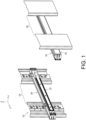
- a fitting assembly is applicable to a rack 22 (or a cabinet) according to a first embodiment of the present invention.
- the rack 22 comprises a first side frame 24 and a second side frame 26, such as a left side frame and a right side frame.
- Structural configuration of the first side frame 24 is substantially identical to or symmetric to structural configuration of the second side frame 26, but the present invention is not limited thereto.
- a first width W1 is defined between the first side frame 24 and the second side frame 26 of the rack 22.
- the fitting assembly comprises a first fitting device 28 and a second fitting device 30.
- Structural configuration of the first fitting device 28 is substantially identical to or symmetric to structural configuration of the second fitting device 30, but the present invention is not limited thereto.
- the first fitting device 28 is configured to be mounted to the first side frame 24 of the rack 22, and the second fitting device 30 is configured to be mounted to the second side frame 26 of the rack 22.
- the manner of mounting the first fitting device 28 to the first side frame 24 is substantially identical to the manner of mounting the second fitting device 30 to the second side frame 26.
- a second width W2 is defined between the first fitting device 28 and the second fitting device 30, and the second width W2 is smaller than the first width W1.
- the first fitting device 28 and the second fitting device 30 are configured to mount a first slide rail assembly 32 and a second slide rail assembly 34 to the first side frame 24 and the second side frame 26 respectively.
- Structural configuration of the first slide rail assembly 32 is substantially identical to or symmetric to structural configuration of the second slide rail assembly 34.
- each of the first slide rail assembly 32 and the second slide rail assembly 34 comprises a first rail 36 (outer rail), a second rail 38 (inner rail), and a third rail 40 (middle rail) movably mounted between the first rail 36 and the second rail 38.
- the number of slide rails is not limited in the present invention.
- a carried object 42 (as shown in FIG.
- the X axis is a longitudinal direction (or a length direction of the slide rail)
- the Y axis is a transverse direction (or a lateral direction of the slide rail)
- the Z axis is a vertical direction (or a height direction of the slide rail).
- the first fitting device 28 comprises a first end part 44a, a second end part 44b and a main body part 46 (longitudinal part) connected between the first end part 44a and the second end part 44b.
- the main body part 46 is arranged with at least one engaging structure 48 configured to be engaged to at least one post 24a (as shown in FIG. 4 ) of the first side frame 24 of the rack 22.
- the post 24a of the first side frame 24 of the rack 22 comprises a plurality of mounting parts 50.
- the mounting parts 50 are arranged at intervals along the height direction of the post 24a of the rack 22.
- the mounting parts 50 are holes, such as square holes, but the present invention is not limited thereto.
- the main body part 46 has an inner side L1 and an outer side L2 opposite to each other.
- the engaging structure 48 is arranged at the outer side L2 of the main body part 46, and the engaging structure 48 is an insertion structure.
- the engaging structure 48 has a first section 52a and a second section 52b (as shown in FIG. 4 ).
- the first section 52a is transversely (laterally) connected to the main body part 46, and the second section 52b is bent relative to the first section 52a.
- the second section 52b is substantially perpendicularly connected to the first section 52a.
- the engaging structure 48 is configured to be inserted into the mounting part 50 (hole) of the rack 22, such that the second section 52b of the engaging structure 48 can be further engaged with a first wall K1 (first hole wall) of the mounting part 50.
- the main body part 46 is further arranged with a locking member 54 and a mounting feature 56 arranged on the locking member 54.
- the mounting feature 56 is configured to lock the engaging structure 48 to the first side frame 24 of the rack 22, in order to prevent the engaging structure 48 from being disengaged from the first side frame 24 of the rack 22 (as shown in FIG. 4 ).
- the locking member 54 is arranged at the inner side L1 of the main body part 46, and the mounting feature 56 is a protruded structure (or extended structure) .
- the mounting feature 56 is configured to pass through an auxiliary hole 58 of the main body part 46 to extend from the inner side L1 to the outer side L2.
- the locking member 54 is elastic, and the mounting feature 56 is configured to be inserted into the mounting part 50 (hole) of the rack 22 in response to an elastic force F of the locking member 54, such that the mounting feature 56 is configured to abut against a second wall K2 (second hole wall) of the mounting part 50, in order to prevent the engaging structure 48 from being disengaged from the rack 22.
- the first fitting device 28 is locked to the first side frame 24 of the rack 22, and unable to be detached from the first side frame 24 of the rack 22 (as shown in FIG. 4 ).
- the first wall K1 and the second wall K2 are two opposite walls, such as a rear wall and a front wall of the mounting part 50 (as shown in FIG. 4 ), but the present invention is not limited thereto.
- the locking member 54 comprises a connecting section 60, an operating section 62 and an elastic section 64 connected between the connecting section 60 and the operating section 62 (as shown in FIG. 3 ).
- the connecting section 60 is connected (such as fixedly connected) to the main body part 46.
- the elastic section 64 is arranged with the mounting feature 56.
- the operating section 62 is connected to the elastic section 64. A user can operate the operating section 62 to move the elastic section 64.
- the operating section 62 is bent relative to the elastic section 64, such that the user can easily pull the operating section 62 to move the elastic section 64.
- a limiting feature 66 (as shown in FIG. 3 ) is arranged at the inner side L1 of the main body part 46 configured to prevent the elastic section 64 from being excessively moved when the user applies an operating force J along a direction opposite to a direction of the elastic force F.
- At least one first connecting feature 68 is arranged adj acent to the first end part 44a, and at least one second connecting feature 70 is arranged adjacent to the second end part 44b.
- the first end part 44a is arranged with a first connecting base 72 substantially perpendicularly bent relative to the main body part 46.
- the first connecting base 72 is bent relative to the main body part 46 along a direction away from the first side frame 24 of the rack 22 (that is, a direction toward the second side frame 26 of the rack 22).
- the first connecting feature 68 is arranged on the first connecting base 72.
- the second end part 44b is arranged with a second connecting base 74 substantially perpendicularly bent relative to the main body part 46.
- the second connecting base 74 is bent relative to the main body part 46 along the direction away from the first side frame 24 of the rack 22 (that is, the direction toward the second side frame 26 of the rack 22).
- the second connecting feature 70 is arranged on the second connecting base 74.
- At least one of the first connecting feature 68 and the second connecting feature 70 is a mounting hole.
- the first connecting feature 68 and the second connecting feature 70 are both mounting holes.
- the mounting holes can be square holes, round holes or screw holes, but the present invention is not limited thereto.
- the user when the user is going to detach the first fitting device 28 from the first side frame 24 of the rack 22, the user can apply the operating force J to the operating section 62 in order to overcome the elastic force F of the locking member 54, so as to move the elastic section 64 inward, such that the mounting feature 56 is moved away from the second wall K2 (second hole wall) of the mounting part 50 (for example, the mounting feature 56 is laterally offset from the second wall K2 of the mounting part 50) .
- the engaging structure 48 is able to be detached from the first wall K1 of the mounting part 50 of the rack 22.
- the first fitting device 28 can be detached from the first side frame 24 of the rack 22 at this time.
- the manner of detaching the second fitting device 30 from the second side frame 26 is substantially identical to the manner of detaching the first fitting device 28 from the first side frame 24, thus no further illustration is provided for simplicity.
- the first fitting device 28 is mounted to the rack 22 (the first side frame 24 of the rack 22), and the first slide rail assembly 32 is configured to be mounted between the first connecting feature 68 and the second connecting feature 70 of the first fitting device 28.
- the first rail 36 of the first slide rail assembly 32 is arranged with a bracket mechanism 76, and the bracket mechanism 76 comprises a first bracket 78 and a second bracket 80 longitudinally movable relative to each other.
- the first bracket 78 is arranged with at least one first connecting part 82 configured to be connected to the first connecting feature 68 of the first fitting device 28.
- the second bracket 80 is arranged with at least one second connecting part 84 configured to be connected to the second connecting feature 70 of the first fitting device 28.
- the manner of mounting the second slide rail assembly 34 to the second fitting device 30 is substantially identical to the manner of mounting the first slide rail assembly 32 to the first fitting device 28, thus no further illustration is provided for simplicity.
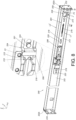
- FIG. 8 shows a second fitting device 200 (structural configuration of the first fitting device is substantially identical to or symmetric to structural configuration of the second fitting device 200) according to a second embodiment of the present invention.
- a main body part 202 of the second fitting device 200 is further arranged with an operating member 204, and the operating member 204 is configured to drive a locking member 206 to move.
- the main body part 202 has a first end part 202a and a second end part 202b, such as a front end part and a rear end part
- the operating member 204 comprises an operating part 208 adjacent to the first end part 202a, such that it is convenient for a user standing in front of the second fitting device 200 (or the first fitting device) to operate the operating part 208 to drive the locking member 206 to move for unlocking the second fitting device 200.
- the operating part 208 further has a bent section 209 to allow the user to easily apply an operating force J' from an inner side L1' of the main body part 202 to pull the operating member 204 to drive the locking member 206 to move.
- the main body part 202 is formed with a predetermined space M (such as a through hole or a notch) communicating the inner side L1' and an outer side L2' of the main body part 202, and the operating member 204 further comprises at least one driving part 210 (for example, the driving part 210 has an inclined surface or an arc surface, but the present invention is not limited thereto) and an extension part 212 connected between the driving part 210 and the operating part 208.
- a predetermined space M such as a through hole or a notch
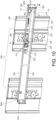
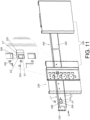
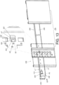
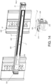
- the operating part 204 has a predetermined hole 214 adjacent to the predetermined space M of the main body part 202 (for example, the predetermined hole 214 corresponds to the predetermined space M), such that the user can easily apply the operating force J' to the operating part 208 from the inner side L1' or the outer side L2' of the main body part 202 to operate the operating member 204 to move from a first predetermined position P1 (as shown in FIG. 8 and FIG. 11 ) to a second predetermined position P2 (as shown in FIG. 12 and FIG.
- first predetermined direction D1 so as to drive an elastic section 201 of the locking member 206 to move (such as deflect) inward to switch from a first state S1 (such as a locking state as shown in FIG. 8 and FIG. 11 ) to a second state S2 (such as an unlocking state as shown in FIG. 12 and FIG. 13 ), such that a mounting feature 224 on the elastic section 201 of the locking member 206 is moved inward to be away from a second wall K2' of a mounting part 236 of a rack 228 (as shown in FIG. 12 and FIG. 13 ).
- first state S1 such as a locking state as shown in FIG. 8 and FIG. 11
- second state S2 such as an unlocking state as shown in FIG. 12 and FIG. 13
- the second fitting device 200 further comprises a return elastic member 216.
- the operating member 204 is configured to be held at the first predetermined position P1 in response to a return elastic force of the return elastic member 216.
- the operating member 204 is longitudinally movable relative to the main body part 202 within a limited range defined by a plurality of pairs of a first limiting structure 218 and a second limiting structure 220.
- the first limiting structure 218 and the second limiting structure 220 are a combination of a protruded part (such as a connecting pin or a connecting bolt) and an elongated hole.
- the protruded part is configured to pass through a portion of the elongated hole.
- the outer side L2' of the main body part 202 is arranged with an engaging structure 222, and the mounting feature 224 on the locking member 206 is configured to pass through an auxiliary hole 226 of the main body part 202 to extend from the inner side L1' to the outer side L2' .
- the second fitting device 200 is mounted to the second side frame 230 of the rack 228 (such mounting configuration has been disclosed in the first embodiment, no further illustration is provided for simplicity).
- the second fitting device 200 is mounted to the second side frame 230 of the rack 228 without mounting a second slide rail assembly between a first connecting feature 232 and a second connecting feature 234 of the second fitting device 200.
- the user can easily operate the operating member 204 to drive the locking member 206 (the elastic section 201 of the locking member 206) to move.
- the user when the user is going to detach the second fitting device 200 from the second side frame 230 of the rack 228, the user can apply the operating force J' (as shown in FIG. 10 and FIG. 11 ) to the operating member 204 (the operating part 208 of the operating member 204) from the inner side L1' or the outer side L2' of the main body part 202 in order to operate the operating member 204 to move from the first predetermined position P1 (as shown in FIG. 10 and FIG. 11 ) to the second predetermined position P2 (as shown in FIG. 12 and FIG. 13 ), such that the driving part 210 of the operating member 204 is configured to contact a corresponding part 215 of the locking member 206 (as shown in FIG.
- the mounting feature 224 is moved toward the inner side L1' of the main body part 202 to be away from the second wall K2' (second hole wall) of the mounting part 236 (hole) of the rack 228 (for example, the mounting feature 224 is laterally offset from the second wall K2' of the mounting part 236 as shown in FIG. 13 ). Therefore, the engaging structure 222 is able to be detached from the first wall K1' (first hole wall) of the mounting part 236 of the rack 228. In other words, the second fitting device 200 can be detached from the second side frame 230 of the rack 228 at this time (as shown in FIG. 13 ).
- the return elastic force of the return elastic member 216 is configured to drive the operating member 204 to move from the second predetermined position P2 (as shown in FIG. 12 and FIG. 13 ) back to the first predetermined position P1 (as shown in FIG. 10 and FIG. 11 ) along a second predetermined direction D2 opposite to the first predetermined direction D1, and the locking member 206 is moved to switch from the second state S2 to the first state S1.
- the second first slide rail assembly 238 is configured to cover most of the inner side L1' of the main body part 202 of the second fitting device 200. Therefore, the user cannot easily operate the operating member 204 (the operating part 208 of the operating member 204) from the inner side L1' of the main body part 202.
- the user's finger can insert into the predetermined hole 214 to extend from the outer side L2' of the main body part 202 to the inner side L1' of the main body part 202 to apply the operating force J' to the operating part 208, in order to operate the operating member 204 to move from the first predetermined position P1 to the second predetermined position P2 along the first predetermined direction D1, such that the mounting feature 224 is moved toward the inner side L1' to allow the engaging structure 222 to be detached from the rack 228, so as to detach the second fitting device 200 from the rack 228 (such configuration has been disclosed above, no further illustration is provided for simplicity).
- the fitting assembly according to the embodiments of the present invention has the following technical features:
Landscapes
- Engineering & Computer Science (AREA)
- Computer Hardware Design (AREA)
- General Engineering & Computer Science (AREA)
- Microelectronics & Electronic Packaging (AREA)
- Drawers Of Furniture (AREA)
- Cabinets, Racks, Or The Like Of Rigid Construction (AREA)
Applications Claiming Priority (1)
| Application Number | Priority Date | Filing Date | Title |
|---|---|---|---|
| TW112145265A TWI850157B (zh) | 2023-11-21 | 2023-11-21 | 配件總成及其配件裝置 |
Publications (1)
| Publication Number | Publication Date |
|---|---|
| EP4561278A1 true EP4561278A1 (fr) | 2025-05-28 |
Family
ID=91810357
Family Applications (1)
| Application Number | Title | Priority Date | Filing Date |
|---|---|---|---|
| EP24186201.0A Pending EP4561278A1 (fr) | 2023-11-21 | 2024-07-03 | Ensemble raccord et son dispositif de raccord |
Country Status (4)
| Country | Link |
|---|---|
| US (1) | US20250160515A1 (fr) |
| EP (1) | EP4561278A1 (fr) |
| JP (1) | JP7832996B2 (fr) |
| TW (1) | TWI850157B (fr) |
Citations (3)
| Publication number | Priority date | Publication date | Assignee | Title |
|---|---|---|---|---|
| EP1403970B1 (fr) * | 2002-09-28 | 2006-07-26 | Tyco Electronics AMP GmbH | Dispositif d'attachement d' une boîte à un rail de montage |
| US10314394B2 (en) | 2016-09-24 | 2019-06-11 | King Slide Works Co., Ltd. | Rail mounting adapter assembly for rack |
| EP3975674A1 (fr) * | 2020-09-24 | 2022-03-30 | King Slide Works Co., Ltd. | Kit de rail coulissant |
Family Cites Families (16)
| Publication number | Priority date | Publication date | Assignee | Title |
|---|---|---|---|---|
| US5833337A (en) * | 1997-05-09 | 1998-11-10 | Sequent Computer Systems, Inc. | Self-retaining rack slide |
| GB9803527D0 (en) * | 1998-02-19 | 1998-04-15 | Reddicliffe Edward A | A method of assembling a cabinet |
| US6948691B2 (en) * | 2000-03-17 | 2005-09-27 | Jonathan Manufacturing Corporation | Computer server mounting apparatus |
| US6702412B2 (en) * | 2001-09-19 | 2004-03-09 | Hewlett-Packard Development Company, L.P. | Expandable slide and rail assembly for a rack and method of installing same |
| US6938967B2 (en) * | 2001-12-12 | 2005-09-06 | Pentair Electronic Packaging Co. | Telescoping slide assembly |
| US6615992B1 (en) * | 2002-03-11 | 2003-09-09 | Hewlett-Packard Development Company L.P. | Adjustable rackmount assembly |
| US6866154B2 (en) * | 2002-12-03 | 2005-03-15 | Dell Products L.P. | Tool-less attachment bracket |
| US7137512B2 (en) * | 2003-02-19 | 2006-11-21 | Hewlett-Packard Development Company, L.P. | Removable rails for use on racks |
| US7230824B2 (en) * | 2004-06-30 | 2007-06-12 | Shuttle Inc. | Clip-on hanger for electrical data storage and retrieval device |
| US7494101B2 (en) * | 2005-08-18 | 2009-02-24 | Protrend Co., Ltd | Hook-on type rail |
| DE102010000279A1 (de) * | 2010-02-02 | 2011-08-04 | Paul Hettich GmbH & Co. KG, 32278 | Auszugsführung eines Schubkastens |
| US8851300B2 (en) * | 2010-12-13 | 2014-10-07 | Proper Storage Systems, LLC | Roll-out shelving storage rack system |
| US9629276B2 (en) * | 2015-05-29 | 2017-04-18 | Oracle International Corporation | Adjustable snap-in rail assembly for storage rack |
| TWI726391B (zh) * | 2019-08-19 | 2021-05-01 | 川湖科技股份有限公司 | 滑軌總成 |
| TWI704890B (zh) | 2019-10-18 | 2020-09-21 | 川湖科技股份有限公司 | 滑軌總成及其滑軌套件 |
| TWI750987B (zh) | 2020-12-30 | 2021-12-21 | 川湖科技股份有限公司 | 滑軌總成 |
-
2023
- 2023-11-21 TW TW112145265A patent/TWI850157B/zh active
-
2024
- 2024-06-06 US US18/736,123 patent/US20250160515A1/en active Pending
- 2024-07-03 EP EP24186201.0A patent/EP4561278A1/fr active Pending
- 2024-07-22 JP JP2024116702A patent/JP7832996B2/ja active Active
Patent Citations (3)
| Publication number | Priority date | Publication date | Assignee | Title |
|---|---|---|---|---|
| EP1403970B1 (fr) * | 2002-09-28 | 2006-07-26 | Tyco Electronics AMP GmbH | Dispositif d'attachement d' une boîte à un rail de montage |
| US10314394B2 (en) | 2016-09-24 | 2019-06-11 | King Slide Works Co., Ltd. | Rail mounting adapter assembly for rack |
| EP3975674A1 (fr) * | 2020-09-24 | 2022-03-30 | King Slide Works Co., Ltd. | Kit de rail coulissant |
Also Published As
| Publication number | Publication date |
|---|---|
| US20250160515A1 (en) | 2025-05-22 |
| TWI850157B (zh) | 2024-07-21 |
| JP7832996B2 (ja) | 2026-03-18 |
| JP2025084049A (ja) | 2025-06-02 |
| TW202521034A (zh) | 2025-06-01 |
Similar Documents
| Publication | Publication Date | Title |
|---|---|---|
| EP3322269A1 (fr) | Dispositif de support et ensemble de rail coulissant comprenant celui-ci | |
| US11439036B2 (en) | Slide rail assembly | |
| EP3975674B1 (fr) | Kit de rail coulissant | |
| US7404736B2 (en) | Patch panel and strain relief bar assembly | |
| EP3082387B1 (fr) | Ensemble de rail de glissement | |
| EP3637968B1 (fr) | Ensemble de gestion de câbles | |
| US6840819B2 (en) | Electrical apparatus to be fitted to a top hat rail | |
| EP3634094A1 (fr) | Ensemble de rails de glissement | |
| EP3300348A1 (fr) | Ensemble adaptateur de montage de rail pour crémaillère | |
| EP3202283B1 (fr) | Dispositif de support | |
| EP3144457B1 (fr) | Système pour rangement avec un ensemble de rail coulissant avec dispositif de verrouillage | |
| EP3661340A1 (fr) | Dispositif de support | |
| EP3833169B1 (fr) | Ensemble rail coulissant | |
| EP3886546B1 (fr) | Ensemble rail coulissant | |
| EP3576507B1 (fr) | Dispositif de support pour système de rayonnage et ensemble de rail de coulissement | |
| EP3383152B1 (fr) | Support pour rail de coulissement | |
| EP3782513B1 (fr) | Ensemble rail coulissant autorisant un jeu latéral | |
| EP3352547A1 (fr) | Ensemble de rails de glissement | |
| EP4125311A1 (fr) | Dispositif de support | |
| EP4537705A1 (fr) | Ensemble rail coulissant | |
| EP3979775B1 (fr) | Ensemble rail coulissant | |
| EP3270669A1 (fr) | Dispositif de support | |
| EP4561278A1 (fr) | Ensemble raccord et son dispositif de raccord | |
| EP4629760A1 (fr) | Ensemble rail coulissant | |
| EP3958658B1 (fr) | Ensemble rail coulissant |
Legal Events
| Date | Code | Title | Description |
|---|---|---|---|
| PUAI | Public reference made under article 153(3) epc to a published international application that has entered the european phase |
Free format text: ORIGINAL CODE: 0009012 |
|
| STAA | Information on the status of an ep patent application or granted ep patent |
Free format text: STATUS: REQUEST FOR EXAMINATION WAS MADE |
|
| 17P | Request for examination filed |
Effective date: 20250227 |
|
| AK | Designated contracting states |
Kind code of ref document: A1 Designated state(s): AL AT BE BG CH CY CZ DE DK EE ES FI FR GB GR HR HU IE IS IT LI LT LU LV MC ME MK MT NL NO PL PT RO RS SE SI SK SM TR |
|
| STAA | Information on the status of an ep patent application or granted ep patent |
Free format text: STATUS: EXAMINATION IS IN PROGRESS |
|
| 17Q | First examination report despatched |
Effective date: 20251021 |
|
| REG | Reference to a national code |
Ref country code: DE Ref legal event code: R079 Free format text: PREVIOUS MAIN CLASS: H05K0007140000 Ipc: A47B0088430000 |
|
| GRAP | Despatch of communication of intention to grant a patent |
Free format text: ORIGINAL CODE: EPIDOSNIGR1 |
|
| STAA | Information on the status of an ep patent application or granted ep patent |
Free format text: STATUS: GRANT OF PATENT IS INTENDED |
|
| RIC1 | Information provided on ipc code assigned before grant |
Ipc: A47B 88/43 20170101AFI20260204BHEP Ipc: H05K 7/14 20060101ALI20260204BHEP |
|
| GRAS | Grant fee paid |
Free format text: ORIGINAL CODE: EPIDOSNIGR3 |
|
| INTG | Intention to grant announced |
Effective date: 20260305 |
|
| GRAA | (expected) grant |
Free format text: ORIGINAL CODE: 0009210 |
|
| STAA | Information on the status of an ep patent application or granted ep patent |
Free format text: STATUS: THE PATENT HAS BEEN GRANTED |