EP4563864A2 - Raccord destiné à être relié à un tuyau - Google Patents
Raccord destiné à être relié à un tuyau Download PDFInfo
- Publication number
- EP4563864A2 EP4563864A2 EP24214133.1A EP24214133A EP4563864A2 EP 4563864 A2 EP4563864 A2 EP 4563864A2 EP 24214133 A EP24214133 A EP 24214133A EP 4563864 A2 EP4563864 A2 EP 4563864A2
- Authority
- EP
- European Patent Office
- Prior art keywords
- pipe
- ring
- additional ring
- fitting
- compression sleeve
- Prior art date
- Legal status (The legal status is an assumption and is not a legal conclusion. Google has not performed a legal analysis and makes no representation as to the accuracy of the status listed.)
- Pending
Links
Images





Classifications
-
- F—MECHANICAL ENGINEERING; LIGHTING; HEATING; WEAPONS; BLASTING
- F16—ENGINEERING ELEMENTS AND UNITS; GENERAL MEASURES FOR PRODUCING AND MAINTAINING EFFECTIVE FUNCTIONING OF MACHINES OR INSTALLATIONS; THERMAL INSULATION IN GENERAL
- F16L—PIPES; JOINTS OR FITTINGS FOR PIPES; SUPPORTS FOR PIPES, CABLES OR PROTECTIVE TUBING; MEANS FOR THERMAL INSULATION IN GENERAL
- F16L13/00—Non-disconnectable pipe joints, e.g. soldered, adhesive, or caulked joints
- F16L13/14—Non-disconnectable pipe joints, e.g. soldered, adhesive, or caulked joints made by plastically deforming the material of the pipe, e.g. by flanging, rolling
- F16L13/141—Non-disconnectable pipe joints, e.g. soldered, adhesive, or caulked joints made by plastically deforming the material of the pipe, e.g. by flanging, rolling by crimping or rolling from the outside
- F16L13/142—Non-disconnectable pipe joints, e.g. soldered, adhesive, or caulked joints made by plastically deforming the material of the pipe, e.g. by flanging, rolling by crimping or rolling from the outside with a sealing element inserted into the female part before crimping or rolling
-
- F—MECHANICAL ENGINEERING; LIGHTING; HEATING; WEAPONS; BLASTING
- F16—ENGINEERING ELEMENTS AND UNITS; GENERAL MEASURES FOR PRODUCING AND MAINTAINING EFFECTIVE FUNCTIONING OF MACHINES OR INSTALLATIONS; THERMAL INSULATION IN GENERAL
- F16L—PIPES; JOINTS OR FITTINGS FOR PIPES; SUPPORTS FOR PIPES, CABLES OR PROTECTIVE TUBING; MEANS FOR THERMAL INSULATION IN GENERAL
- F16L37/00—Couplings of the quick-acting type
- F16L37/08—Couplings of the quick-acting type in which the connection between abutting or axially overlapping ends is maintained by locking members
- F16L37/084—Couplings of the quick-acting type in which the connection between abutting or axially overlapping ends is maintained by locking members combined with automatic locking
- F16L37/092—Couplings of the quick-acting type in which the connection between abutting or axially overlapping ends is maintained by locking members combined with automatic locking by means of elements wedged between the pipe and the frusto-conical surface of the body of the connector
- F16L37/0926—Couplings of the quick-acting type in which the connection between abutting or axially overlapping ends is maintained by locking members combined with automatic locking by means of elements wedged between the pipe and the frusto-conical surface of the body of the connector with an inner support sleeve arranged within the pipe
-
- F—MECHANICAL ENGINEERING; LIGHTING; HEATING; WEAPONS; BLASTING
- F16—ENGINEERING ELEMENTS AND UNITS; GENERAL MEASURES FOR PRODUCING AND MAINTAINING EFFECTIVE FUNCTIONING OF MACHINES OR INSTALLATIONS; THERMAL INSULATION IN GENERAL
- F16L—PIPES; JOINTS OR FITTINGS FOR PIPES; SUPPORTS FOR PIPES, CABLES OR PROTECTIVE TUBING; MEANS FOR THERMAL INSULATION IN GENERAL
- F16L2201/00—Special arrangements for pipe couplings
- F16L2201/10—Indicators for correct coupling
Definitions
- the invention relates to a fitting for connecting to a pipe with a base body, with a stop element formed circumferentially in the base body and projecting inwards, with a press sleeve connected to the base body, wherein the press sleeve has a chamber directed inwards towards the pipe to be received, and with a sealing element arranged in the chamber, wherein the press sleeve is suitable, together with the sealing element, for sealing the pipe to be connected from the outside.
- a fitting is essentially a connecting piece for a pipeline, and a fitting is most commonly used to connect two or more pipe sections. Accordingly, the fitting preferably has two or more press sections, for example in the form of press sleeves.
- the most common fittings include straight connections, changes of direction in the form of pipe bends, reducers, branches such as T-pieces or intersections.
- a fitting can also be understood to mean a pipe connection of a valve or other component. For example, thermometers or pressure gauges, as valves, only have one connection for one pipe section. Thus, the fitting of a valve only has one press section to connect a pipe section to the valve.
- Press connections are used to connect the pipe sections with the fittings and other components.
- a press section of a fitting is formed radially inwards by means of a press jaw when the pipe section is inserted, so that a permanent and tight, possibly even permanent, connection is created.
- the connection is established.
- the fittings can be provided with a sealing agent, such as an O-ring, to ensure the tightness of the connection, or they can be designed to seal by means of direct contact between the materials of the pipe section and the fitting, for example, a metallic seal.
- the pressing technology used for radial forming of the pressing section primarily includes radially acting pressing systems as well as pressing systems that use radial-axial pressing, whereby a part of the fitting is displaced axially during the pressing process in order to effect radial forming.
- the pipeline systems described above are primarily used to transport drinking or heating water, gas for operating a heating system, or industrial gases.
- any fluid medium can be transported in the pipelines.
- the present invention therefore relates to fittings in which the pipe is sealed and secured from the outside or from the inside.
- Solid materials are used for pipes to be sealed from the outside.
- Solid plastics can also be considered as solid materials. Suitable materials for this purpose include metals, for example, stainless steels such as ferritic steels such as 1.4520, 1.4521, austenitic steels such as 1.4404, duplex steels such as 1.4462, gunmetal, SiBr, copper, but also solid plastics such as cross-linked polyethylene (PE-X), polyethylene with increased temperature resistance (PE-RT), polyvinyl chloride (PVC), and polypropylene (PP) with appropriate wall thicknesses.
- multi-layer composite pipes can be designed to be sufficiently rigid for sealing from the outside, for example, using a thicker aluminum layer. Fiber-reinforced pipes can also be used. Pipes that require internal sealing can be made of the same plastics or a composite of plastic and metal layers, but with a thinner wall thickness, ensuring flexibility through the geometric design.
- the described fittings and their components are preferably made of a metal to ensure formability with sufficient hardness and dimensional stability after forming.
- the metals already mentioned for the rigid pipes are suitable, for example, stainless steels such as ferritic steels such as 1.4520 and 1.4521, austenitic steels such as 1.4404, duplex steels such as 1.4462, gunmetal, SiBr, and copper.
- the described fittings and their components can also be made of a non-metallic material or plastic if the non-metallic material has sufficient properties for pressing and permanently connecting to pipes.
- suitable materials include the following: cross-linked polyethylene (PE-X), silane-cross-linked polyethylene (PE-Xb) or physically cross-linked polyethylene (PE-Xc), polyethylene with increased temperature resistance (PE-RT), polyvinyl chloride (PVC), polypropylene (PP) with appropriate wall thicknesses, polyphenyl sulfone (PPSU), polyetheretherketone (PEEK) or polyaryletherketone (PAEK), aliphatic bio-based polyamide (PA410, PA12, PA12-GF30), or polypropylene random copolymer with modified crystal structure and increased temperature resistance (PP-RCT).
- PE-X cross-linked polyethylene
- PE-Xb silane-cross-linked polyethylene
- PE-Xc physically cross-linked polyethylene
- PE-RT polyvinyl chloride
- PVC polyprop
- Fittings for connecting to a pipe that requires external sealing can have various designs.
- a sealing ring such as an O-ring, is provided to seal the fitting against the outside of the pipe.
- Clamp rings, retaining elements, and/or fixing elements are also provided to secure the pipe in the required position relative to the fitting before and after pressing.
- the base body of the clamping ring is made of plastic and has a closed ring shape. To insert the clamping ring into a fitting or into the undercut chamber of the compression sleeve, it must be compressed radially. Axial slots may be provided to facilitate compression.
- the clamping ring can also be designed as a strip, which is bent or rounded before being inserted into the fitting.
- viewing windows can be incorporated into the press sleeve, which allow a view of the inserted pipe and thus a control of the insertion depth.
- the sealing element is preferably positioned adjacent to the stop element and thus as low as possible in the insertion direction of the pipe. This avoids dead spaces between the inserted pipe and the compression sleeve in the pressed state.
- the sealing element is preferably made of an elastomeric material.
- the main function of the additional ring is to enable insertion depth control, as described below.
- the fitting connects a pipe to be sealed from the outside.
- the pipe is inserted into the fitting or the open distal end of the compression sleeve by radial compression in preparation for assembly. This process can be verified by the user by touch, as the pipe strikes the stop element at the end of the insertion, thus creating high resistance to the pressing force.
- the additional ring rests circumferentially against the outside of the pipe, at least in sections. This creates a static friction force, and the additional ring and the pipe move together in sections.
- the sealing element and the compression sleeve are arranged in relation to the pipe in such a way that pressing the compression sleeve with a pressing tool results in a secure and tight connection between the fitting and the pipe.
- the sealing element creates a seal by pressing between the outside of the pipe and the inside of the compression sleeve. If the pipe were not in contact with the sealing element, the connection would be incomplete and faulty. If the pipe were in contact with the sealing element but were to be pulled out again a little, the pressed connection would no longer be as mechanically stable as it would be if it were correctly positioned.
- the additional ring As the tube is inserted, the additional ring is moved to its proximal position, i.e., a position that is positioned as far axially as possible into the fitting. When the tube rests against the stop element, the user receives haptic feedback that the tube has been inserted sufficiently. In this position, the additional ring protrudes only partially, slightly, for example, as a color-coded protruding collar, or is completely accommodated by the distal end of the compression sleeve. This arrangement provides the fitting user with an indication that the tube is correctly positioned.
- the additional ring also moves axially out of the fitting due to static friction.
- an increasingly larger part of the additional ring protrudes from the distal end of the compression sleeve and is available for the Visible to the user. Visibility can be enhanced by warning colors or other markings.
- the user can therefore determine whether the pipe is correctly positioned for pressing or not based on the position of the additional ring relative to the press sleeve.
- the additional ring thus preferably has at least one marking to indicate the position relative to the compression sleeve.
- the marking can be single-colored, multi-colored, or structured.
- a slight withdrawal of the pipe may not be harmful to a pressed connection, since the sealing element remains in contact with the outside of the pipe and the pipe is positioned sufficiently far into the base body of the fitting.
- the marking can therefore be designed in such a way that the user can detect a slight but harmless deviation from the desired position.
- the additional ring By further pulling out the tube, the additional ring can be moved further toward the distal position until it stops in the distal position. The additional ring then remains in the distal position, even if the tube is pulled out further. In any case, the tube is no longer correctly positioned for crimping.
- the fitting has a relatively large distance between the stop element and the sealing element. Therefore, after insertion and after pressing, the pipe is guided or held within the fitting and proximally by the sealing element through the base body and, if necessary, through a part of the compression sleeve. This ensures the bending strength and the pull-out strength of the pressed connection. Even small changes in the positioning of the pipe within the fitting, i.e., only a slight withdrawal of the pipe from the proximal position in the distal direction, can However, this can lead to deterioration of the pressed connection. In this case, the additional ring indicates that the pipe was not optimally positioned before pressing.
- the distance between the proximal position and the distal position is less than the distance between the stop element and the sealing element.
- the additional ring has at least one radially inwardly projecting retaining projection for engagement with a pipe to be inserted.
- the at least one retaining projection comes into contact with the surface of the pipe, so that the additional ring does not otherwise bear against the pipe.
- the at least one retaining projection can be designed as a largely continuous ring, but at least two retaining projections can also be arranged distributed around the circumference.
- the additional ring preferably has stop elements that project radially outward or in the azimuthal direction. These stop elements can interact with the compression sleeve or—as explained below—with a clamping ring to limit the movement of the additional ring between the proximal and distal positions.
- the additional ring is thus slidably received in the compression sleeve and preferably in the chamber formed therein.
- the additional ring can be loosely slidably received in the compression sleeve, with the proximal and distal positions being defined by corresponding stops on the compression sleeve.
- the compression sleeve has a chamber directed inward toward the pipe to be received, and the sealing element is arranged in the chamber.
- the fitting also has a clamping ring arranged in the compression sleeve. The additional ring engages with the clamping ring, and the clamping ring guides the additional ring during axial movement. Stops are provided to limit the movement between the proximal and distal positions of the additional ring relative to the clamping ring.
- the stop elements are formed on axially extending tabs, wherein the tabs are connected to a ring.
- the ring is arranged in the region of the distal opening of the compression sleeve, and the tabs extend axially into the compression sleeve.
- the tabs are elastically bendable inward, so that the additional ring can be easily mounted in the compression sleeve and within the clamping ring.
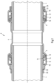
- the fitting 2 has an additional ring 20, which is accommodated in the clamping ring 14 so that it can be displaced axially.
- the additional ring 20 can therefore be displaced axially relative to the clamping ring 14 and thus relative to the compression sleeve 10 without affecting the holding and fixing function of the clamping ring 14.
- the additional ring 20 is between a Fig. 1 and 2 proximal position shown on the left and one in Fig. 1 and 2
- the additional ring 20 can be displaced into the distal position shown on the right.
- the additional ring 20 In the proximal position, the additional ring 20 is displaced axially inward into the base body 6 and is completely received in the compression sleeve 10.
- the additional ring 20 In the distal position, the additional ring 20 partially protrudes from the distal end of the compression sleeve 10.
- Fig. 2 shows the fitting 2 with inserted tube 4.
- the tube 4 rests with its outer side against the additional ring 20 and displaces the additional ring 20 through static friction during an axial movement.
- the additional ring 20 is displaced into the proximal position, as shown in Fig. 2 shown on the right. In this position, the tube 4 rests against the stop element 8 and The clamping ring 14 and the sealing element 18 rest against the outside of the pipe 4.
- This position of the pipe 4 is the desired position in which the pipe 4 can be firmly and sealingly connected to the fitting 2 by radially pressing the compression sleeve 10.
- the correct position is signaled to the user during insertion by the mechanical resistance caused by the tube 4 being in contact with the stop element 8.
- the tube 4 When pulled out, the tube 4 displaces the additional ring 20 axially outward due to the contact by means of static friction.
- the additional ring 20 thus becomes partially visible and can be perceived as a signal by the user. This state is exemplified in Fig. 2 shown on the left. If the additional ring 20 is visible from the outside, the user can see that the current position of the pipe 4 within the fitting is incorrect.
- Fig. 3 shows the previously described fitting 2 with the additional ring 20, which is displaced outward from the compression sleeve 10 into the distal position. This allows the additional ring 20 to protrude and provide a signaling effect.
- the additional ring 20 has a different color (gray) than the color of the base body 6 (white) as a marking.
- a color gradient, stepped color sections or even a surface structuring to indicate the position relative to the compression sleeve 10 can also be provided as a marking.
- Fig. 4 shows a side view of the fitting 2 with the base body 6 shown in grey and with the pipes 4 inserted.
- the pipe 4 also shown in grey, is inserted up to the stop element 8.
- the associated additional ring 20 cannot be seen from the outside.
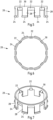
- the Fig. 5 to 7 show the additional ring 20 in different views and the Fig. 8 to 10 also show the clamping ring 14 in different views.
- the additional ring 20 and the clamping ring 14 are adapted to each other to realize the insertion depth control function.
- the additional ring 20 initially has a plurality of radially inwardly projecting retaining projections 22 for engagement with a pipe 4 to be inserted.
- the inner diameter on the inner sides of the retaining projections is slightly smaller than the outer diameter of the pipe 4 to be inserted.
- the retaining projections 22 come into sufficiently strong contact to realize the entrainment by the pipe 4 through static friction.
- the additional ring 20 has radially outwardly projecting stop elements 24 and the clamping ring 14 has circumferentially distributed and axially extending recesses 26 for displaceably receiving the stop elements 24.
- the interaction is particularly Fig. 1
- the recesses 26 accommodate the stop elements 24 in the axial direction , whereby the length of the recesses 26 determines the range of motion and the proximal position and the distal position.
- the stop elements 24 are further formed on axially extending tabs 28 and the tabs 28 are connected to a ring 30.
- the clamping ring 14 shown has a plurality of ring elements 32, each of which is pivotally connected to one another by hinge elements 34.
- the ring elements 32 serve to hold and fix a pipe 4 to be inserted.
- the ring elements 32 have a strip shape due to the hinge elements 34.
- the ring elements 32 can therefore assume a flat shape, where "flat” essentially means that the ring elements 32 can rest on a surface.
- the ring elements 32 can also have a laterally open ring shape by means of the hinge elements 34 as in Fig. 8 to 10 shown.
- the clamping ring 14 thus has a C-shape that is open on one side.
- the flat arrangement has the advantage that the ring elements 32 can be easily equipped with further elements without a ring shape leading to complex process steps.
- the ring elements 32 have a partially cylindrical outer surface 36 that is adapted to the cylindrical shape of the fitting or the chamber of the associated compression sleeve. This allows the clamping ring 14 to rest flatly against the inside of the compression sleeve 10, at least in sections. In the flat shape of the clamping ring 14, the partially cylindrical outer surfaces then rest in sections on a substrate.
- clamping ring 14 can also be designed as a closed ring and have alternating ring elements 32 with different functions.
- a portion 32a of the ring elements 32 is formed with the clamping projections 16 described above, which rest against the outside of the pipe 4 when inserted and perform a guiding function. In the inserted state, the clamping projections then hold the pipe 4 and fix it before pressing.
- the additional ring 20 has stop elements 24 which engage in recesses 40 formed in the wall of the compression sleeve 10.
- the recesses 40 extend in the axial direction, so that the additional ring 20 can be positioned between a Fig. 12 us 13 right shown distal position and one in the Fig. 12 13 shown on the left is movable in the proximal position.
- the additional ring 20 does not protrude from the compression sleeve 10, whereas in the distal position shown on the left, the additional ring 20 visibly protrudes outward in the axial direction. In the distal position, the user of the fitting 2 is thus signaled that the tube 4 is not positioned correctly in the compression sleeve 10 or in the fitting 2.
- the distance between the proximal position and the distal position of the additional ring is less than the distance between the stop element 8 and the sealing element 18. This corresponds to the dimensioning of the fitting 2 according to Fig. 1 to 4 .
Landscapes
- Engineering & Computer Science (AREA)
- General Engineering & Computer Science (AREA)
- Mechanical Engineering (AREA)
- Quick-Acting Or Multi-Walled Pipe Joints (AREA)
Applications Claiming Priority (1)
| Application Number | Priority Date | Filing Date | Title |
|---|---|---|---|
| DE102023132502.7A DE102023132502A1 (de) | 2023-11-22 | 2023-11-22 | Fitting zum Verbinden mit einem Rohr |
Publications (2)
| Publication Number | Publication Date |
|---|---|
| EP4563864A2 true EP4563864A2 (fr) | 2025-06-04 |
| EP4563864A3 EP4563864A3 (fr) | 2025-07-30 |
Family
ID=93607539
Family Applications (1)
| Application Number | Title | Priority Date | Filing Date |
|---|---|---|---|
| EP24214133.1A Pending EP4563864A3 (fr) | 2023-11-22 | 2024-11-20 | Raccord destiné à être relié à un tuyau |
Country Status (2)
| Country | Link |
|---|---|
| EP (1) | EP4563864A3 (fr) |
| DE (1) | DE102023132502A1 (fr) |
Family Cites Families (7)
| Publication number | Priority date | Publication date | Assignee | Title |
|---|---|---|---|---|
| US8585100B2 (en) * | 2009-08-27 | 2013-11-19 | Elkhart Products Corporation | Press-connect fitting with improved grab ring function |
| EP2366933A1 (fr) * | 2010-03-03 | 2011-09-21 | R. Nussbaum AG | Pièce de raccordement pour tuyaux métalliques |
| AT512772B1 (de) * | 2012-09-10 | 2013-11-15 | Ke Kelit Kunststoffwerk Gmbh | Steckkupplung für ein metallisches Rohr, insbesondere für Wasserleitungen |
| DE102013015895B4 (de) * | 2013-09-25 | 2019-01-10 | Conex Ipr Ltd. | Pressfitting und Verbindungsanordnung mit einem solchen Pressfitting |
| DE102015109268B4 (de) * | 2015-06-11 | 2025-06-18 | Viega Technology Gmbh & Co. Kg | Fitting mit Befestigungselement und Verfahren zur Herstellung einer dichten Verbindung |
| NL2015413B1 (en) * | 2015-09-08 | 2017-03-22 | Vsh Fittings B V | Press fitting for pipes having a check ring. |
| US10865914B2 (en) * | 2017-04-28 | 2020-12-15 | Nibco Inc. | High temperature leak prevention for piping components and connections |
-
2023
- 2023-11-22 DE DE102023132502.7A patent/DE102023132502A1/de active Pending
-
2024
- 2024-11-20 EP EP24214133.1A patent/EP4563864A3/fr active Pending
Also Published As
| Publication number | Publication date |
|---|---|
| EP4563864A3 (fr) | 2025-07-30 |
| DE102023132502A1 (de) | 2025-05-22 |
Similar Documents
| Publication | Publication Date | Title |
|---|---|---|
| DE3879674T2 (de) | Schnellkupplung fuer rohre oder schlaeuche mit einem kegelfoermigen haltering. | |
| EP2703707B1 (fr) | Système de fabrication d'une liaison étanche | |
| EP4334049B1 (fr) | Système de raccordement de tuyaux rigides et de raccordement des tuyaux flexibles | |
| DE102017105505A1 (de) | Fitting zum Verbinden mit mindestens einem Rohr und Verfahren zum Herstellen einer Verbindung | |
| EP4551858A1 (fr) | Bague de serrage pour un raccord, et raccord comprenant une bague de serrage | |
| EP2404097B1 (fr) | Système de raccord pour le raccord d'un tuyau à un tuyau principal | |
| DE202020102046U1 (de) | Rohrleitungsverbindungsstruktur | |
| DE102013108442A1 (de) | Baueinheit mit einem Rohr und einem Kupplungselement sowie Verfahren zur Herstellung einer derartigen Baueinheit | |
| EP3244119A1 (fr) | Élement d'etancheite | |
| DE19838125C1 (de) | Rohrverbinder für Kunststoffrohre und/oder Kunststoff/Metall-Verbundrohre | |
| EP3043101B1 (fr) | Manchon d'etancheite | |
| DE102005061516B4 (de) | Fitting mit einem Dichtring | |
| EP3940281B1 (fr) | Manchon de tuyau | |
| EP1775507B1 (fr) | Raccord pour des tuyaux | |
| EP4563864A2 (fr) | Raccord destiné à être relié à un tuyau | |
| WO2024188788A1 (fr) | Raccord et système de raccordement de tuyaux à une unité fonctionnelle | |
| AT525084B1 (de) | Rohrpresskupplung | |
| DE102022131932A1 (de) | Funktionselement mit intumeszierendem Material | |
| DE10217824C1 (de) | Rohrverbindung | |
| EP1927804B1 (fr) | Raccord de tuyauterie | |
| DE102023132504A1 (de) | Klemmring für einen Fitting und Fitting mit einem Klemmring | |
| DE102016116652A1 (de) | Hybridfitting zum Anschluss an ein Ende eines Rohres | |
| DE102023132503A1 (de) | Klemmring für einen Fitting und Fitting mit einem Klemmring | |
| DE102014216184A1 (de) | Presshülse | |
| EP0454976B1 (fr) | Dispositif pour relier un tuyau en matière synthétique à un autre tuyau |
Legal Events
| Date | Code | Title | Description |
|---|---|---|---|
| PUAI | Public reference made under article 153(3) epc to a published international application that has entered the european phase |
Free format text: ORIGINAL CODE: 0009012 |
|
| STAA | Information on the status of an ep patent application or granted ep patent |
Free format text: STATUS: THE APPLICATION HAS BEEN PUBLISHED |
|
| AK | Designated contracting states |
Kind code of ref document: A2 Designated state(s): AL AT BE BG CH CY CZ DE DK EE ES FI FR GB GR HR HU IE IS IT LI LT LU LV MC ME MK MT NL NO PL PT RO RS SE SI SK SM TR |
|
| PUAL | Search report despatched |
Free format text: ORIGINAL CODE: 0009013 |
|
| AK | Designated contracting states |
Kind code of ref document: A3 Designated state(s): AL AT BE BG CH CY CZ DE DK EE ES FI FR GB GR HR HU IE IS IT LI LT LU LV MC ME MK MT NL NO PL PT RO RS SE SI SK SM TR |
|
| RAP3 | Party data changed (applicant data changed or rights of an application transferred) |
Owner name: VIEGA TECHNOLOGY GMBH & CO. KG |
|
| RIC1 | Information provided on ipc code assigned before grant |
Ipc: F16L 13/14 20060101AFI20250625BHEP Ipc: F16L 37/092 20060101ALI20250625BHEP |
|
| STAA | Information on the status of an ep patent application or granted ep patent |
Free format text: STATUS: REQUEST FOR EXAMINATION WAS MADE |
|
| 17P | Request for examination filed |
Effective date: 20251208 |