EP4563983A1 - Analyse de qualité d'imagerie basée sur une image - Google Patents
Analyse de qualité d'imagerie basée sur une image Download PDFInfo
- Publication number
- EP4563983A1 EP4563983A1 EP23213562.4A EP23213562A EP4563983A1 EP 4563983 A1 EP4563983 A1 EP 4563983A1 EP 23213562 A EP23213562 A EP 23213562A EP 4563983 A1 EP4563983 A1 EP 4563983A1
- Authority
- EP
- European Patent Office
- Prior art keywords
- data array
- mask layer
- openings
- imager
- image
- Prior art date
- Legal status (The legal status is an assumption and is not a legal conclusion. Google has not performed a legal analysis and makes no representation as to the accuracy of the status listed.)
- Pending
Links
Images


Classifications
-
- G—PHYSICS
- G01—MEASURING; TESTING
- G01N—INVESTIGATING OR ANALYSING MATERIALS BY DETERMINING THEIR CHEMICAL OR PHYSICAL PROPERTIES
- G01N21/00—Investigating or analysing materials by the use of optical means, i.e. using sub-millimetre waves, infrared, visible or ultraviolet light
- G01N21/84—Systems specially adapted for particular applications
- G01N21/88—Investigating the presence of flaws or contamination
- G01N21/95—Investigating the presence of flaws or contamination characterised by the material or shape of the object to be examined
- G01N21/956—Inspecting patterns on the surface of objects
- G01N21/95607—Inspecting patterns on the surface of objects using a comparative method
-
- G—PHYSICS
- G03—PHOTOGRAPHY; CINEMATOGRAPHY; ANALOGOUS TECHNIQUES USING WAVES OTHER THAN OPTICAL WAVES; ELECTROGRAPHY; HOLOGRAPHY
- G03F—PHOTOMECHANICAL PRODUCTION OF TEXTURED OR PATTERNED SURFACES, e.g. FOR PRINTING, FOR PROCESSING OF SEMICONDUCTOR DEVICES; MATERIALS THEREFOR; ORIGINALS THEREFOR; APPARATUS SPECIALLY ADAPTED THEREFOR
- G03F7/00—Photomechanical, e.g. photolithographic, production of textured or patterned surfaces, e.g. printing surfaces; Materials therefor, e.g. comprising photoresists; Apparatus specially adapted therefor
- G03F7/20—Exposure; Apparatus therefor
- G03F7/2002—Exposure; Apparatus therefor with visible light or UV light, through an original having an opaque pattern on a transparent support, e.g. film printing, projection printing; by reflection of visible or UV light from an original such as a printed image
- G03F7/2014—Contact or film exposure of light sensitive plates such as lithographic plates or circuit boards, e.g. in a vacuum frame
- G03F7/2016—Contact mask being integral part of the photosensitive element and subject to destructive removal during post-exposure processing
- G03F7/202—Masking pattern being obtained by thermal means, e.g. laser ablation
-
- G—PHYSICS
- G06—COMPUTING OR CALCULATING; COUNTING
- G06T—IMAGE DATA PROCESSING OR GENERATION, IN GENERAL
- G06T7/00—Image analysis
- G06T7/0002—Inspection of images, e.g. flaw detection
- G06T7/0004—Industrial image inspection
- G06T7/001—Industrial image inspection using an image reference approach
Definitions
- Transferring images to flexographic printing plates typically comprises placing a flexographic printing plate on a standard digital imager, such as a Cyrel ® Digital Imager (CDI TM ), manufactured by Esko Graphic-Imaging GmbH of Itzehoe, Germany.
- a standard digital imager such as a Cyrel ® Digital Imager (CDI TM ), manufactured by Esko Graphic-Imaging GmbH of Itzehoe, Germany.
- CDI TM Cyrel ® Digital Imager
- State of the art flexographic printing plates typically have a Laser Ablatable Mask system (LAMs) layer disposed on top of the printing (front) surface of the plate.
- LAMs Laser Ablatable Mask system
- the LAMs layer is partially removed by an infrared laser beam in the imager in a pattern corresponding to the image to the transferred.
- the photopolymer is selectively cured by UV light that penetrates the portions of the plate where the LAMs layer was removed. This second process step is usually done in a second device outside the imager.
- the non-cured portions of the photopolymer plate are selectively removed by a thermal or solvent process.
- Pixel boosting allows creation of micro screens in the mask of a digital photopolymer printing plate (e.g. DuPont ® Cyrel ® DPR) by ablating only individual single pixels. These single pixels are arranged in patterns that form surface structures in regions of the plate intended to transfer ink to the print substrate. The capability of ink transfer of such surface structures is optimized by choosing an optimum size for the individual mask openings. The size of the mask openings can be altered by adjusting the energy of the laser pulse that creates the mask opening. Additional information regarding exemplary such techniques can be found in U.S. Patent No. 11,142,013 (“the '013 Patent”), titled “Method for smoother tonal response in flexographic printing,” incorporated herein by reference.
- the mask openings are cut by a multitude of beams simultaneously.
- This multitude of beams can be operated in two different modes: standard imaging mode or pulsed mode.
- standard imaging mode the laser power for each individual beam is selected in a way that the size of the mask opening just slightly overlaps with the mask openings cut by neighboring beams.
- the beams are switched "on" continuously in solid rendition areas, according to the image information of the image to be printed, such that the opening in a mask for a solid rendition area extends across the entire solid rendition area.
- solid rendition area refers to an area of an image to which a halftone screen has not been applied, which image areas may also include "linework" - e.g.
- This mode is used for standard imaging, and creates solid rendition screened areas, including linework, having no surface structures (e.g. while highlight areas may comprise a plurality of discrete and separated halftone dots formed on the plate, the surface of each solid rendition area is not textured).
- the laser power for each beam in this mode is nominally considered to be at 100% power.
- pulsed mode the beams are turned on for short periods. Not all beams are turned on at the same time. Instead, the beams are turned on in certain sequences, forming patterns of mask openings that build surface structures that are suitable for improved ink transfer.
- An exemplary method for forming such surface structures is disclosed in U.S. Patent No. 11,142,013 B2 ("the '013 Patent"), titled “METHOD FOR SMOOTHER TONAL RESPONSE IN FLEXOGRAPHIC PRINTING,” which is incorporated herein by reference.
- Exemplary state-of-the-art micro screen patterns are disclosed, for example, in PCT Application No. PCT/EP2021/083548 , titled "SYSTEM AND METHOD FOR MITIGATING TRAILING EDGE VOIDS IN FLEXO PRINTING," the content of which is incorporated herein by reference.
- the different sizes of mask openings result in different structures on the completely processed polymer plate. These structures can be varied from individually separate standing micro screen dots to dots all touching another, leaving only small holes in between. Controlling the surface structures in the completely processed plate allows adjusting the surface properties of the plate for optimum print properties.
- One of the challenges of using digital photopolymer printing plates concerns impartially or objectively assessing the imaging quality of CDI imaging on the LAMs layer. Criteria for assessing the imaging quality (e.g. the correct focus position of the imaging optics) are commonly assessed by human operators or technicians either by looking at the LAMs layer through a microscope or by measuring mask openings of test patterns which were imaged onto the LAMs layer at different focus positions by means of densitometers. When CDI imagers developed from single imaging beam to multibeam imagers that use 64 or more beams, additional criteria became relevant.
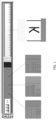
- balancing between individual beams may be conventionally addressed by special test patterns such as the DFTA Test pattern, as developed by DFTA Flexobuch horr said e.V., depicted in FIG. 1 .
- DFTA Test pattern was designed for imagers having between 2 to 8 beams and image file resolutions between 2000 and 2540 DPI, when more imaging beams were later used, and the image file resolution went up to 4000 DPI or higher, more sophisticated patterns were developed and used.
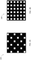
- FIGS. 2A and 2B Such patterns can also be applied as surface structures to improve ink transfer, as described, for example, in the aforementioned '013 Patent as well as in U.S. Patent No.
- Non-limiting examples of a selection of criteria for assessing the imaging quality include: power balancing of the imaging beams, distance between imaging beams, beam rake tilt, and circumferential position jitter of imaging beams.
- Other non-limiting examples of a selection of criteria for assessing the imaging quality if single pixel microscreen patterns (e.g. MCWSI pattern, depicted in FIG. 7A of the '311 Patent) are imaged, include: correct circular shape of the mask openings, homogeneity of the mask openings, horizontal or vertical deviation of mask openings from the expected position, and undesired patterning in microscreens.
- state-of-the-art selection of criteria for assessing imaging quality of CDI imaging on the LAMs layer are assessed by humans, either by assessing pictures taken from the imaged LAMs layer or by directly looking at the LAMs layer through a magnifier or a microscope with illumination from the plates top- or backside.
- the pictures of the imaged LAMs layer can be taken for example by the Flex 3 Pro TM flexo plate analyser, from Peret GmbH.
- One aspect of the invention comprises a system for performing quality analysis of an imaged printing plate precursor mask layer having a plurality of openings created by a first imager corresponding to information in an image file.
- the information in the image file includes micro-screen information comprising a pattern of "on” and “off” single pixels or clusters thereof.
- the printing plate precursor comprises a photopolymer configured to be cured by exposure to actinic radiation through openings in a mask layer.
- the system has a detector configured for acquiring a digital image of at least a sample portion of the plurality of openings formed in the mask layer corresponding to the micro-screen information for inspection
- the system also includes computer memory media programmed with a first set of machine-readable instructions for causing a processor to analyze the digital image and generate, based on the digital image, a first data array comprising a plurality of inspection parameters related to each of the plurality of openings in the mask layer.
- the system has a computer memory media programmed with a second set of machine-readable instructions for comparing the plurality of inspection parameters from the first data array and a plurality of reference parameters from a second data array.
- Another aspect of the invention comprises a method for performing quality analysis of an imaged printing plate precursor mask layer having a plurality of openings created by a first imager corresponding to information in an image file.
- the information in the image file includes micro-screen information comprising a pattern of "on” and “off” single pixels or clusters thereof.
- the printing plate precursor has a photopolymer configured to be cured by exposure to actinic radiation through openings in a mask layer.
- the method comprises the steps of imaging the mask layer of the printing plate according to the information in the image file by causing the controller connected to the imager to transform image information in the image file to commands for causing the imager to create the openings in the mask layer; generating a digital image of at least a sample portion of the plurality of openings formed in the mask layer corresponding to the micro-screen information for inspection; generating a first data array comprising a plurality of inspection parameters related to each of the plurality of openings in the mask layer; and comparing the plurality of inspection parameters from the first data array and a plurality of reference parameters from a second data array.
- Yet another aspect of the invention comprises a non-transitory computer memory media programmed with machine-readable instructions for causing a processor to perform quality analysis of a printing plate mask layer created by an imager based upon information in an image file including micro-screen information comprising a pattern of "on" and "off” single pixels or clusters thereof.
- the instructions include a first set of instructions for retrieving a digital image of at least a sample portion of the openings formed in the mask layer corresponding to the micro-screen information for inspection.
- the instructions also have a second set of machine-readable instructions for analyzing the digital image and generating, based on the digital image, a first data array comprising a plurality of inspection parameters related to the individual openings in the mask layer.
- the instructions further include a third set of machine-readable instructions for comparing the plurality of inspection parameters from the first data array and a plurality of reference parameters from a second data array.
- the instructions include a fourth set of machine readable instructions comprising at least one of: (i) instructions for comparing the one or more deviations detected using a first instance of the first data array generated at a first time to the one or more deviations detected using a second instance of the first data array generated at a second time, and providing an alert if the comparison indicates a change over time greater than a predetermined threshold, and (ii) instructions for retrieving a third data array comprising at least the calculated average values of the plurality of inspection parameters (e.g.
- the instructions also include a fifth set of machine-readable instructions comprising at least one of: (i) instructions for recommending or automatically initiating a change in at least one setting of the imager based upon the detected one or more deviations; and (ii) instructions for causing the processor to render, and an output device attached to the processor to output, an image visualizing the comparison of and deviations between the plurality of inspection parameters from at least two of the first instance of the first data array, the second instance of the second data array, the second data array, and the third data array.
- the changes in the at least one setting of the imager take the form of a reconfigured beam balancing instruction table, generated by applying correction factors to a prior beam balancing instruction table, wherein the correction factors are based upon the deviations between the first data array and ideal reconstructions based upon the first data array.
- yet another aspect of the invention relates to a method for imaging beam balancing of an imager, the imager configured to emit a plurality of imaging beams for ablating a plurality of openings in a mask layer of a printing plate precursor in accordance with information in an image file, the imager comprising a controller configured to translate the information in the image file into an amount of energy selectively applied by the plurality of imaging beams to selected locations on the mask layer.
- the imager has initial beam balancing information stored in computer memory and used by the controller for defining a power intensity output supplied to each imaging beam.
- the method comprises imaging the mask layer of the printing plate with the imager according to the information in the image file using the initial beam balancing information, generating a digital inspection image of at least a sample portion of the plurality of openings formed in the mask layer imaged using the initial beam balancing information, generating a first data array comprising a plurality of inspection parameters related to each of the plurality of openings in the mask layer of the digital inspection image; generating a reference data array comprising a reconstruction of the first data array with idealized reference parameters for each of the plurality of openings in the mask layer generated from data in the first data array, and detecting and calculating one or more deviations between corresponding reference parameters and inspection parameters.
- a set of one or more correction factors for modifying the power intensity output of the one or more imaging beams is developed based upon the detected and calculated one or more deviations, and the one or more correction factors are applied to the existing beam balancing information to form corrected beam balancing information.
- One aspect of the invention addresses the problem of image quality assessments of an imager for digital plates by analyzing microscreen patterns corresponding to different settings for "on” and “off” pixels in various regions of the printed image. Aspects of the invention also relate to specific methods for performing image quality assessments.
- microscreen patterns comprising mask openings formed by switching "on" single pixels or clusters of multiple pixels to determine one or more deviations relative to a reference appearance of the microscreen pattern.
- Exemplary microscreen patterns are illustrated in FIGS. 2A (referred to by the Applicant as an MCWSI pattern) and 2B ( referred to by the Applicant as a DDWSI pattern), but one skilled in the art would understand from the description herein that other test or microscreen patterns are applicable, including any pattern comprising mask openings created by switching "on" single pixels or clusters of multiple pixels.
- the exemplary systems and methods herein may be used to perform an image quality assessment of or based on Moire patterns.
- the exemplary systems and methods described herein collect and analyze a plurality of data points related to the micro screen imaging parameters in an image of a flexographic printing plate when imaging the LAMs layer of the plate. In doing so, analysis of the microscreen test patterns improves the printing properties of the printing plate, such as the ink transfer property of the printing plate. In an exemplary embodiment, this improvement in printing properties of the printing plate is achieved by measuring the existing beam balancing on an imager 810 (CDI imager), comparing these measured values to predetermined or ideal readings of an idealized identical pattern, calculating correction values for all beams, and applying these correction values for imaging. Application of correction values can be established by replacing an existing balancing information stored by a controller (e.g.
- intensity values of all beams e.g. in a beam balancing instruction table
- corrected balancing information e.g. in a beam balancing instruction table
- the exemplary systems and methods are discussed herein in the context of assessing the imaging properties of an imager for digital photopolymer printing plates, but the exemplary systems and methods described herein can also be applied for Offset or Inkjet imagers or other imaging systems within the field of graphic arts.
- the invention of analyzing a digital image of microscreen patterns to assess imaging quality as discussed herein is not limited only to LAMs layer mask technology, but can instead be applied broadly to other types of masking layers used during a curing step of a photopolymer plate (e.g. silver halide or thermal film-based masks), without limitation.
- the term "printing plate” is intended to include, and may refer to, a printing plate precursor not yet completely finished or a finished plate ready to receive ink, the specifics of which will be clear from the context of the discussion herein.
- finished printing plate refers to a plate that is fully developed and ready to receive ink
- plate precursor refers to a plate at any stage of development prior to being a finished plate ready to receive ink.
- FIG. 8 An exemplary system 800 for performing an image quality analysis of a printing plate having a printing surface corresponding to an information in an image file is shown in FIG. 8 .
- a printing plate comprises a photosensitive polymer on which is disposed a mask that defines portions of the plate that are masked from radiation exposure relative to portions of the plate that are desired to receive such exposure (i.e. for curing).
- the polymer, including in the mask area is permeable to oxygen.
- the information in the image file includes micro-screen information comprising a pattern of "on” and "off” single pixels or clusters thereof (as shown in FIGS. 2A-2B , for example).
- An exemplary system 800 for carrying out embodiments of the invention described herein, as depicted in FIG. 8 comprises an imager 810 (such as the Esko ® CDI imager), a controller 820 for the imager 810, and computer memory media 830 programmed with a first set of machine-readable instructions 832, a detector 880, a computer memory media 850 programmed with a second set of machine-readable instructions 852, and computer memory media 860 programmed with a third set of machine-readable instructions 862.
- the plurality of reference parameters and plurality of inspection parameters may comprise but is not limited to a size, a shape, a position, an orientation, and a homogeneity of the openings formed in the mask layer.
- computer memory media 840 is configured to store measurements and other data collected during a cycle of image quality assessment (e.g. performed in accordance with method 900 discussed below) of one or more printing plates.
- the first set of machine-readable instructions 832 is configured to cause the controller 820 connected to the imager 810 to transform image information in the image file to commands for causing the imager 810 to create the openings in the mask layer.
- at least 5000 mask openings should be formed in the mask layer.
- Printing plate properties such as capability of ink transfer of such surface structures, can be optimized based on a characteristic of the individual mask openings formed, e.g. an optimum size for the individual mask openings.
- the different sizes of mask openings result in different structures on the completely processed polymer plate.
- structures can be varied from individually separate standing micro screen dots to dots all touching another, leaving only small holes in between. Controlling the surface structures in the completely processed plate allows adjusting the surface properties of the plate for optimum print properties.
- system 800 includes the detector 880.
- the detector 880 is integrated with the imager 810.
- the detector 880 is external and separate from the imager 810, such as in an embodiment in which the detector is a stand-alone device located at a light table where the imaged plates are inspected.
- the detector 880 is configured for generating a digital image of a sample portion of at least the openings formed in the mask layer corresponding to the micro-screen information for inspection.
- the detector 880 comprises a camera 888 ( FIG. 8 ) and optionally, one or more optical elements to generate a magnified digital image of the sample portion.
- the detector 880 should preferably provide minimal optical distortion, and if distortions do exist, corrective actions may be performed, including taking pictures of a reference grid that is known to be linear and compensating for the distortions visible in the digital image.
- the camera 888 comprises a plurality of pixels that is at least 500 times more than a number of the imaged openings in the sample portion for inspection.
- the camera 888 includes a resolution of 5 megapixels or higher.
- Exemplary cameras 888 include a Bresser ® model DST-1028 camera having 5.1 megapixels, a Basler ® acA4024-29um USB 3.0 camera with the Sony ® IMX 226 CMOS sensor.
- a magnification setting may be set to 200, which permits imaging of approximately 5000 spots of an exemplary microscreen pattern 300, such as one of the patterns depicted in FIGS. 2A-2B and 3 (the latter of which is referred to by the Applicant as a MCDWS pattern).
- the second set of machine-readable instructions 852 comprise instructions for causing the detector 880 to generate the digital image, non-limiting examples of which are illustrated in FIGS. 2A and 3 showing an exemplary MCWSI screen 300.
- a first data array 200 related to the digital image of the microscreen 300 is generated, the first data array 200 being illustrated as a matrix of data points in FIG. 4 .
- the first data array 200 includes a plurality of inspection parameters related to the individual openings created in the mask layer.
- the second set of machine-readable instructions 852 comprise instructions for calculating an average value for each respective one of the plurality of inspection parameters. In this way, the second set of machine-readable instructions 852 also includes instructions for generating a second data array comprising optimal parameters by assessing the plurality of inspection parameters and the calculated average values thereof.
- the third set of machine-readable instructions 862 comprise instructions for comparing the plurality of inspection parameters from the first data array and a plurality of reference parameters from the second data array.
- the third set of machine-readable instructions 862 comprise instructions for calculating one or more deviations, if any, between the plurality of inspection parameters from the first data array and the plurality of reference parameters from the second data array.
- the third set of machine-readable instructions 862 comprise instructions for detecting one or more deviations between a data point from the first data array and a corresponding data point from the second data array.
- analysis or comparison of the data points are performed using an image analysis algorithm embodied in software programmed in Python).
- image analysis software operating systems, or programming systems equipped with capabilities for analyzing a digital image or photo of a micro screen pattern
- MCWSI micro screen pattern
- the disclosed systems and methods herein can be used for quality check purposes, such as during manufacturing or servicing of CDI imaging systems.
- balancing between individual beams of multibeam imagers is achieved by performing the exemplary imaging quality assessments disclosed herein.
- Conventional imagers usually have a set of instructions for the beams that are used for imaging, but these instructions are typically limited to parameters or settings related to absolute output power in physical dimensions e.g. Watts.
- the CDI imaging system comprises an acousto-optical deflector that transfers RF signals into optical beams split from a laser, with each beam having a direction dependent upon the frequency and intensities of the RF signal amplitude, such as is described in more detail in U.S. Pat. No. 5,654,125 , titled LASER APPARATUS AND PROCESS OF USE, incorporated herein by reference.
- the invention as described herein is applicable to any type of imager, the exemplary embodiment as described herein relates to such an acousto-optical embodiment.
- balancing information based on summarized measurements of the active beams.
- the light intensity for each physical beam is switched on at a constant drive signal and is measured individually by a photodiode. That is, only one beam at a time is switched on during the measuring period.
- the balancing information for each individual beam is measured in a first step by switching on each single beam individually at a constant drive power, as depicted in FIGS. 15A-15D , which show a relative beam percent intensity for beams 1, 3, 7, and 9 of a 9 beam system, which schematically depicts the relation between individual beams (and their position in the frequency range) and their light intensity measured somewhere between the modulator and the imaging drum of the imager.
- each of the remaining beams in the array (2, 3-6, and 8) have similar measurement steps and corresponding graphs.
- each of these beams may produce a slightly different optical power despite use of the same RF drive power.
- beam 1 in FIG. 15A registers at slightly above 60%
- beam 3 in FIG. 15B registers at slightly above 80%
- beam 7 in FIG. 15C registers at about 70%
- beam 9 in FIG. 15D registers at about 55%.
- the outer beams have less intensity than the center beams in an unbalanced state, as depicted in FIG. 16A.
- FIG. 16B depicts "ideal" balancing according to the prior art methods.
- Beam patterns other than "all beams on” typically have some intensity mismatch after the prior art balancing step involving measurement of only one beam at a time, but this mismatch can be reduced, such as shown in the more ideally balanced depiction in FIG. 17A , when using the balancing method as described herein.
- optical power is measured for every beam (e.g. as illustrated in FIGS. 15A-15D ) and the information as measured is used for creating a balancing instruction table, which includes parameters to be applied to each beam to create a more balanced output.
- a second measurement step all beams for a certain beam combination are switched on and measured together, without knowing the individual contribution of each beam.
- the balancing information derived from the first step is applied.
- the total drive power is then modified using the balancing relationships until the total power complies with the target power. This results in a more balanced arrangement, such as is depicted in FIG. 16B .
- the systems and methods as described herein facilitate a different approach, wherein the intensity of each active beam may be assessed in a single step by switching on all beams of the certain beam combination to be examined, capturing a digital image of the resulting mask openings, analyzing the mask openings created by the different beams, and adjusting the balancing settings accordingly.
- This process is facilitated by use of a special imaging pattern comprising complimentary groups of shifted rows and columns of pixels, for example, as shown in FIG. 18 and discussed in more detail below, such that all beams are visible in the pattern.
- the systems and methods disclosed herein provide a plurality of balancing instructions comprising correction factors that are calculated from a comparison or assessment of one or more deviations detected between the plurality of inspection parameters, such as from the first data array or the second data array, and the plurality of reference parameters, such as from the third data array.
- a method for imaging beam balancing of an imager may include imaging the mask layer of the printing plate with the imager according to the information in the image file using the initial beam balancing information, such as provided by creating balancing information based upon a single beam at a time measurement as illustrated in FIGS. 15-A-D , and then generating a digital inspection image of at least a sample portion of the plurality of openings formed by a suitable test pattern in the mask layer imaged using the initial beam balancing information.
- FIG. 18 illustrates an exemplary test pattern 1800.
- the pattern comprises a first grouping 1810 of "on” pixels 1830 arranged in rows and columns with “off” pixels 1840 separating the "on” pixels, and a second grouping 1820 of on pixels and off pixels, in which the "on” pixels are shifted relative to those in the first group.
- group 1810 comprises a first row 1812 comprising an "on” pixel 1830 in every fourth column, with "off” pixels 1840 forming a gap between the "on” pixels (i.e.
- columns 1851, 1852, 1853, 1855, 1856, and 1857 have off pixels and columns 1854 and 1858 have an on pixel in row 1812), a second row 1814 with only “off” pixels, and a third row 1816 with a "on” pixel every fourth column, but with the "on” columns in row 1816 centered between the "on” columns of row 1812 (i.e. columns 1851, 1853, 1854, 1855, 1857, 1858, and 1859 have off pixels and columns 1852 and 1856 have an on pixel in row 1816).
- a fourth row 1818 contains only "off” pixels. This four-row pattern repeats four times.
- Group 1820 comprises a first row 1822 comprising an "on” pixel in every fourth column, with “off” pixels forming a gap between the "on” pixels, but with the on pixels located in a column not having an on pixel in group 1810 (i.e. columns 1852, 1853, 1854, 1856, 1857, and 1858 have off pixels and columns 1851, 1855, and 1859 have an on pixel in row 1822), a second row 1824 with only "off” pixels, and a third row 1826 with a "on” pixel every fourth column, but with the "on” columns in row 1826 centered between the "on” columns of row 1822 (i.e.
- each of columns 1851-1859 have a plurality of instances in the pattern, wherein each of the 9 columns corresponds to one of the nine beams in an array. It should be understood that the pattern in FIG. 18 is only one example, without limitation, as any (preferably regular) pattern that uses all beams to create single pixel mask openings would work so long as each mask opening can be clearly identified without touching neighboring mask openings.
- a first data array comprising a plurality of inspection parameters related to each of the plurality of openings in the mask layer of the digital inspection image is generated, and then a reference data array comprising a reconstruction of the first data array with idealized reference parameters for each of the plurality of openings in the mask layer is generated from data in the first data array.
- One or more deviations between corresponding reference parameters and inspection parameters are detected and calculated, and then a set of one or more correction factors for modifying the power intensity output of the one or more imaging beams based upon the detected and calculated one or more deviations is developed.
- the correction factors are then applied to the existing beam balancing information to form corrected beam balancing information.
- the disclosed systems and methods herein can be used for continuously or randomly monitoring the imaging quality, thereby permitting detection of a deterioration of the imaging quality before such deterioration materializes downstream, e.g. becomes visible in the print.
- comparison of the plurality of inspection parameters from the first data array and a plurality of reference parameters from the second data array is displayed via an exemplary graphic user interface, such as shown in FIG. 5 .
- the imaging quality assessment may be performed after imaging the full printing plate or after imaging a portion thereof (e.g. to form a small test pattern onto the printing plate).
- the disclosed systems and methods herein can be implemented into UV curing stations, as described, for example, in US20220349796A1 , titled PROCESS AND APPARATUS FOR AUTOMATIC MEASUREMENT OF DENSITY OF PHOTOPOLYMER PRINTING PLATES, which is incorporated herein by reference, or may be incorporated in combination with other imagers and UV curing stations.
- the image acquisition system as described herein may be structured similar to the density measurement system as described therein, wherein rather than a densitometer collecting radiation density information transmitted through a specialized target formed on the plate, a camera captures visual information at a suitable resolution to characterize the openings through which the non-actinic radiation is transmitted through or reflected by the plate.
- the image acquisition system as described herein may be configured as schematically shown in FIG. 10A , which depicts an apparatus 100 for coordinated front and back exposure of a photosensitive printing plate 130 mounted on a transparent substrate 160 (such as glass) and comprising a photosensitive polymer 134 on which is disposed a laser-ablated mask (LAMS) layer 132.
- a camera 110 configured to capture visual information at a suitable resolution to characterize the openings through which the non-actinic radiation (e.g. from source 112) is transmitted through the plate 130 -- is spaced apart from and adjacent a front side of the plate (FS), sometimes also referred to as the main side or printing side of the plate.
- FS front side of the plate
- One or more curing sources of actinic radiation 120, for curing the plate from the back side are provided.
- multiple front side curing radiation sources 122, 124 are shown, other embodiments may have only a single curing source on the front side.
- only a single back side curing radiation source 120 is depicted, other embodiments may have multiple back side curing sources or no backside sources at all.
- Relative movement between the plate 130 and the image quality assessment system is triggered by a drive mechanism 140 controlled by a controller/control system 142, as is known in the art.
- Camera 110 may be attached to one or more processors 150, for operating the camera to acquire and store the image data in memory 170, and for processing the image data pursuant to the various processing techniques as discussed herein.
- carriage 1130 represents a mechanism for moving both the front side actinic curing radiation source 1120 and back side linear radiation source 1122 relative to plate 1114 mounted on transparent surface 1112, such as a glass plate.
- Carriage 1130 may comprise a single housing split in the middle to accommodate the plate between an upper housing portion and a lower housing portions (e.g. upper housing 103 and lower housing 104 housings depicted in FIG. 10A , respectively).
- Each of the actinic radiation sources 1120, 1122 extend to cover one dimension of the plate, which in the example shown shall be referred to as the transverse direction.
- the carriage traverses the plate in the longitudinal (or lateral) direction along arrow L, with at least one source, and preferably both sources, activated. While the exposure step may be performed in a single pass, in some embodiments the exposure may be performed in a plurality of passes, in which each pass imparts radiation using both banks of sources at a fraction of the total exposure needed to provide a desired amount of exposure.
- Source 1120 is depicted as a single source in FIG. 10B to reduce clutter, but may comprise more than one source (such as in the embodiment depicted in FIG. 10A ). Multiple sources may be used on the front side versus back side due to the relatively greater amount of exposure generally used on the front side relative to the back side, in practice.
- the overall mechanism for creating the exposure may comprise a table having an outer frame 1110 that holds a transparent (e.g. glass) stage 1112 on which plate 1114 is disposed.
- a transparent (e.g. glass) stage 1112 on which plate 1114 is disposed.
- the upper portion of the carriage 1130 (disposed above the plate) holds the camera 1150 and the lower portion of the carriage holds non-actinic radiation source 1152 for providing light to be transmitted through the plate and the mask toward the camera.
- the relative positions above and below the plate of the source and the camera may be reversed.
- the positions of the camera 1150 and non-actinic radiation source 1152 may be stationary, or the camera 1150 and non-actinic radiation source may be fixed relative to one another, but configured to traverse the carriage 1130 in the transverse direction in the direction of arrow T using any mechanism for providing such motion as is known in the art.
- the radiation sources are coupled to a power source 1124, such as an electrical power cord having sufficient slack to extend the full range of motion of the carriage.
- Tracks (not shown) disposed on the outer frame portion provide a defined path for the gantry system or carriage to traverse.
- the carriage may be moved on the tracks by any drive mechanism 1140 known in the art (also coupled to the power supply 1124 and the controller 1142), including a chain drive, a spindle drive, gear drive, or the like.
- the drive mechanism for the carriage may comprise one or more components mounted within the carriage, one or more components fixed to the table, or a combination thereof.
- a position sensor (not shown) is preferably coupled to the carriage to provide feedback to the controller regarding the precise location of the carriage at any given time.
- the control signal output from the controller for operating the radiation sources and for controlling motion of the carriage may be supplied via a wired or wireless connection.
- the controller may be mounted in a fixed location, such as coupled to the table with a control signal cable attached to the sources similar to the power cable, or may be mounted in or on the carriage.
- control system and drive mechanism cooperate to cause back and forth relative motion in a transverse direction between the radiation from the respective radiation sources and the plate.
- a drive mechanism configured to move the portion of the table containing the plate past stationary upper and lower linear radiation sources, as well as embodiments in which the radiation sources cover less than the full width of the plate and are movable in both the transverse and longitudinal direction to provide total plate coverage (or the plate is movable in both directions, or the plate is movable in one of the two directions and the sources are movable in the other direction to provides the full range of motion required to cover the entire plate).
- the printing plate may be flexible enough to be disposed around a transparent cylinder, such as a glass cylinder, or the plate may be in the form of a continuous sleeve, as is known in the art, with the distances between the light sources arranged relative to the rotational direction of the cylinder, as generally depicted in FIG. 10C and described in more detail herein later.
- the printing plate 730 may be mounted on a transparent (e.g. glass) cylinder 760 rotating at a predetermined speed along arrow A, with the main actinic radiation source 710 disposed in a first location along the cylindrical path of rotation adjacent the external surface of the cylinder, and the back side actinic radiation source 720 disposed in a second location along the cylindrical path of rotation adjacent the internal surface of the cylinder, with the respective locations of the sources spaced apart by the distance required to provide a desired time delay between back and front exposure for the given speed of rotation.
- Sources 710 and 720 may be linear sources, or sources configured to travel parallel to the axis of rotation of the drum while the drum rotates.
- Non-actinic radiation source 752A is disposed opposite camera 750A.
- the image capture system defined by non-actinic radiation 752A and camera 750A may be stationary, or may move in a transverse direction parallel to the axis of rotation of the drum.
- the invention is not limited to any particular disposition of the density measurement system.
- the positions of the non-actinic radiation source 752A and the camera 750A may be reversed, or the components 750A, 752A may be disposed so that one or the other component may be commonly housed with actinic radiation source 720.
- the image capture system may be positioned along the circumference of the cylinder in any position desired.
- the location of the actinic radiation sources and/or the speed of rotation may be variable to provide variable time delays, in which case the image capture system components are preferably in a fixed position, or positioned such that they retain a fixed relationship with one another, notwithstanding any repositioning of the actinic radiation sources.
- the image capture components may be freestanding in a position that does not interfere with the range of movement of the actinic radiation components.
- the photosensitive printing plate 730 may be a sleeve, such as a sleeve designed to fit over the transparent cylinder 760 of the system described above, or may be flat, but sufficiently flexible, to permit it to be disposed on and secured to the surface of the cylinder.
- transparent as used herein may refer to any material that permits a desired amount of radiation at the desired wavelength pass through the selected material.
- transparent as used herein, may refer to a material that is not visibly transparent or even translucent to the human eye.
- the image capture system is a transmission-based system.
- Embodiments using image capture systems that provide the source and camera on the same side of the plate as the mask (i.e. the printing side) may also be used for practicing aspects of the invention.
- FIG. 10D depicts an embodiment 700B comprising a reflection arrangement, in which the non-actinic radiation source 752B is positioned not to emit light through the plate, but rather to reflect light off of the relevant portion of the plate (and mask) towards the camera 750B.
- the system 700A depicted in FIG. 2A (and 10C ) is in every way otherwise identical to system 700B depicted in FIG. 10D .
- a reflection image capture configuration may also be used in a flatbed system as depicted in FIGS. 10A and 10B , in configurations that are identical to those depicted in FIGS. 10A and 10B , but with the non-actinic radiation source and camera disposed on the same side (i.e. front, mask side) of the plate in a reflective arrangement.
- the disclosed systems and methods herein can be used for beam correction which improves or optimizes one or more beam balancing characteristics of imager 810, thereby mitigating or preventing instances of detected or measured imaging quality imperfections.
- image capture or acquisition for use in the method of beam balancing correction provides for light transmission through the mask layer by one or more illumination sources of non-actinic radiation from the front or printing side.
- this type of backlight illumination requires modifications to the drum arrangement or additional steps that are difficult to achieve.
- openings into the side of the drum can be added, such that light can enter the drum through said openings and is reflected towards the backside of the plate via another set of openings defined by the cylinder surface of the drum.
- modifying the drum is typically cumbersome and expensive because of the high mechanical tolerances typically maintained for this approach, and changing the reflectance of the drum surface may undesirably change the imaging result.
- the disclosed systems and methods herein provide for a backside illumination of the masking layer that enters the plate from the imaging/print or front side (i.e. from above the masking layer).
- areas 1100 of the mask containing one or more test patterns are interrupted or surrounded by areas of plain areas of 100% mask openings (preferably created by ablation, but optionally created by any means) 1100, as illustrated in FIG. 11 .
- the plurality of openings formed in the mask layer may be arranged such that the area containing the test patterns 1200 is surrounded by an area containing 100% mask openings 1210, as depicted in FIG. 12 . Still further, FIG.
- FIG. 13 depicts an alternative configuration in which an empty (or blank, 100% opening) reference area 1320 in the center of a non-imaged area 1310 surrounded by 100% opening area) is used to create a background photo that can later be subtracted or removed from the photo of the test pattern (in order to avoid misinterpretation due to non-homogeneity by the ablation stain pattern (e.g. dust or tracks of on-removed LAMs between the beams or beam rakes) or the illumination itself).
- an empty (or blank, 100% opening) reference area 1320 in the center of a non-imaged area 1310 surrounded by 100% opening area) is used to create a background photo that can later be subtracted or removed from the photo of the test pattern (in order to avoid misinterpretation due to non-homogeneity by the ablation stain pattern (e.g. dust or tracks of on-removed LAMs between the beams or beam rakes) or the illumination itself).
- light is transmitted through the mask layer 1405 by one or more illumination sources 1420 of non-actinic radiation from the front side, such that light (as illustrated by rays 1422) illuminate the background of the test pattern after transmission through the polymer 1440 and reflection off of the backing layer 1430 of the printing plate precursor.
- illumination sources 1420 of non-actinic radiation from the front side, such that light (as illustrated by rays 1422) illuminate the background of the test pattern after transmission through the polymer 1440 and reflection off of the backing layer 1430 of the printing plate precursor.
- shading 1410 is provided to prevent direct light from the illumination sources (as illustrated by rays 1424) reaching the camera from reflections from the top side of the mask.
- a background image is captured of the reference area 1320 ( FIG. 13 ) and an image of area 1200 ( FIG. 12 ) containing the test pattern is also captured.
- the illumination readings from the reference area are subtracted from the illumination readings of the test pattern to obtain the true reading of the test pattern without inhomogeneity (e.g. due to the illumination through mask openings not being as homogenous as light from a light table from the back side of the plate).
- the disclosed systems and methods herein avoids the complicated, expensive alternative of changing the drum design for imaging quality assessment.
- the disclosed systems can be integrated or retrofitted on an imager to facilitate image quality assessment, without requiring changes to the conventional drum.
- the analysis may be performed on any portion or location of the printing plate.
- the test patterns may be imaged on waste portions of the plate.
- An advantage of imaging on a waste portion is that this imaging may be performed before imaging of the portion of the plate actually intended for printing, which may facilitate identification of problems with imaging quality (e.g. wrong focus position of imaging optics) before the critical part of the plate is image (thus avoiding the waste and delays of having to re-do an entire plate).
- the image capture system is not limited to the use of visible wavelengths.
- the radiation used for image capture may be any wavelength, preferably one that does not cure the photopolymer (although embodiments may be implemented that utilize the actinic radiation during the curing process), and thus the image may be captured using any type of receiver configured to receive the transmitted or reflected non-actinic radiation in a manner capable of providing the information as described herein at the desired resolution.
- the relative movement between the combined image capture / curing radiation sources and the plate may be provided by any mechanism known in the art for moving objects relative to a horizontal, vertical, or otherwise disposed stationary objects.
- the sources may be disposed on a gantry system having arms that pass the respective sources on the relevant side(s) of a stationary plate.
- the plate may be mounted on any mechanism known in the art, such as a movable stage configured to move relative to fixed image capture / curing radiation sources on opposite sides of the stage.
- the image capture system may also be applied to mechanisms for rotating a cylinder on which a plate is mounted relative to fixed image capture / curing radiation sources system. Similarly, mechanisms for rotating sources relative to a fixed cylinder on which the plate is mounted may also be used. Thus, mechanisms for moving one or more elements relative to another are well known in the art, generally, and the invention is not limited to any particular mechanism.
- an image capture system as described herein may be integrated with any of the mechanisms for providing relative movement between a plate and front/back curing exposure sources as discussed in U.S. Patent Application Publication No.
- the disclosed systems and methods herein can be implemented into a fully automated production system for printing plates, as described for example, in US20230126302A1 , WO2022144291A1 or US20200016916A1 (titled SYSTEM AND PROCESS FOR PERSISTENT MARKING OF FLEXO PLATES AND PLATES MARKED THEREWITH), all of which are incorporated herein by reference.
- the disclosed systems and methods herein are not limited to performing an imaging quality assessment of the mask layer or film required for UV curing of flexographic printing plates; rather, the disclosed systems and methods herein can also be applied to the cured and processed printing plates, in which a picture of the microstructures on the plate can be analysed similarly (e.g.
- the disclosed systems and methods for imaging quality assessment is useful to verify that one or more steps involved in the overall preparation of a printing plate (e.g. UV curing, processing (washing the plate), drying and/or UV finishing) has been executed properly or meet the desired expectations.
- steps involved in the overall preparation of a printing plate e.g. UV curing, processing (washing the plate), drying and/or UV finishing
- the printing plate includes a printing surface corresponding to an information in an image file, and the information in the image file includes micro-screen information comprising a pattern of "on" and "off” single pixels or a cluster thereof. Additionally, the printing plate comprises a photopolymer cured through openings in a mask layer. Additional details of the method 900 is discussed below in the context of the system 800 described above.
- a mask layer of the printing plate is imaged according to the information in the image file.
- the controller 820 connected to the imager 810 is configured to transform image information in the image file to commands for causing the imager 810 to create the openings in the mask layer.
- a digital image of a sample portion of at least the openings formed in the mask layer corresponding to the micro-screen information is generated for inspection.
- the digital image comprises a set of horizontal and vertical stripes corresponding to at least one group of openings in the mask layer forming horizontal rows or vertical columns of openings, respectively.
- a first data array comprising a plurality of inspection parameters related to the individual openings in the mask layer is generated.
- the plurality of reference parameters and plurality of inspection parameters comprise a size, a shape, a position, an orientation (relative to each other), and a homogeneity of the pattern of openings.
- optimal parameters related to the openings in the mask layer are generated based on the digital image of the sample portion. In one example, an average value is calculated for each respective one of the plurality of inspection parameters, such that, a second data array comprising optimal parameters is generated by assessing the plurality of inspection parameters and the calculated average values thereof.
- a plurality of inspection parameters from the first data array is compared with a plurality of reference parameters from a second data array. Additionally, or optionally, the plurality of inspection parameters from the first data array is compared with a plurality of ideal parameters determined from a reconstruction of the plurality of inspection parameters (as shown and discussed with references to FIGS. 6A-6B herein). Correction values are calculated based upon deviations between the inspection parameters as shown in FIG. 6A and the ideal reconstruction as shown in FIG. 6B and those correction values are applied to improve the balancing of the beams.
- the digital image comprises a set of horizontal and vertical stripes corresponding to at least one group of openings in the mask layer forming horizontal rows or vertical columns of openings, respectively
- differences in average mask opening can be assessed or determined along horizontal and vertical directions.
- the horizontal and vertical stripes correspond to relatively lighter (see 302 in FIG. 3 ) or darker stripes (see 301 in FIG. 3 ) in a mask layer comprising microcells patterns.
- Various imaging imperfections may contribute to the resulting horizontal and vertical stripes of varying light transmissivity, such as misbalancing, wrong beam positioning and modulating patterns.
- these darker or lighter stripes of light transmission in the mask layer while perceptible to the human eye, are complex and difficult to quantify for comparison. In most cases, these imperfections result in visible stripes that are oriented along the imaging direction, direction, and can sometimes be transferred into the print.
- step 950 when one or more deviations between the plurality of inspection parameters and the plurality of reference or ideal parameters, or other imaging imperfections, are measured or detected (e.g. due to a misbalancing of the beams), one or more compensation factors for the measured or detected imaging imperfection is applied (e.g. for balancing the imaging beams), as described herein, thereby mitigating or eliminating the detected or measured imperfections.
- FIG. 7C illustrates a digital image generated in step 910, the digital image comprising such horizontal and vertical lines/stripes (in this case, imaging direction is along the vertical direction).
- the image is sliced into a multitude of horizontal and vertical slices that are oriented parallel to the lines that are constituted by the horizontal and vertical rows of mask openings.
- the average light transmission of each slice is then analysed and displayed in a graph as depicted in FIGS. 7A and 7B .
- FIG. 7A light transmission average readings of the vertical rows of mask openings and mask non-openings from the digital image in FIG. 7C are shown.
- FIG. 7B light transmission average readings of the horizontal rows are shown.
- 7A and 7B represents the average light transmission through the mask layer (e.g. by one or more illumination sources of non-actinic radiation).
- the scale at the bottom stands for the number of the row that is analysed.
- the light transmission of the analysed vertical rows fluctuates relatively more compared to that of the horizontal rows, thereby confirming the visual impression that the picture in FIG. 7C has visible vertical lines.
- an improved or more precise and impartial/objective assessment of the strength of the visible stripes and their probability for ink transfer is provided by the disclosed systems and methods herein.
- the digital image is used to build or reconstruct another image having ideal mask openings.
- This reconstruction of the original image makes it easier to identify incorrect or inaccurate placement of mask openings, and can be used to analyze the difference between the plurality of inspection parameters and the plurality of reference parameters corresponding to optimal parameters (e.g. regarding position of mask openings).
- FIG. 6B Such a reconstruction based on the digital image is shown in FIG. 6B , which may be stored in computer memory media 840 and/or without being displayed to human operators via an exemplary user interface.
- the plurality of reference parameters from the third data array comprising at least calculated average values of the plurality of inspection parameters is shown in FIG. 6A
- the reconstruction image having ideal mask openings as shown in FIG.
Landscapes
- Physics & Mathematics (AREA)
- Engineering & Computer Science (AREA)
- General Physics & Mathematics (AREA)
- Life Sciences & Earth Sciences (AREA)
- Analytical Chemistry (AREA)
- Theoretical Computer Science (AREA)
- Optics & Photonics (AREA)
- Health & Medical Sciences (AREA)
- Quality & Reliability (AREA)
- Chemical & Material Sciences (AREA)
- Computer Vision & Pattern Recognition (AREA)
- Biochemistry (AREA)
- General Health & Medical Sciences (AREA)
- Immunology (AREA)
- Pathology (AREA)
- Manufacture Or Reproduction Of Printing Formes (AREA)
- Analysing Materials By The Use Of Radiation (AREA)
Priority Applications (2)
| Application Number | Priority Date | Filing Date | Title |
|---|---|---|---|
| EP23213562.4A EP4563983A1 (fr) | 2023-11-30 | 2023-11-30 | Analyse de qualité d'imagerie basée sur une image |
| PCT/EP2024/084378 WO2025114615A2 (fr) | 2023-11-30 | 2024-12-02 | Analyse de qualité d'imagerie basée sur une photographie |
Applications Claiming Priority (1)
| Application Number | Priority Date | Filing Date | Title |
|---|---|---|---|
| EP23213562.4A EP4563983A1 (fr) | 2023-11-30 | 2023-11-30 | Analyse de qualité d'imagerie basée sur une image |
Publications (1)
| Publication Number | Publication Date |
|---|---|
| EP4563983A1 true EP4563983A1 (fr) | 2025-06-04 |
Family
ID=89073113
Family Applications (1)
| Application Number | Title | Priority Date | Filing Date |
|---|---|---|---|
| EP23213562.4A Pending EP4563983A1 (fr) | 2023-11-30 | 2023-11-30 | Analyse de qualité d'imagerie basée sur une image |
Country Status (2)
| Country | Link |
|---|---|
| EP (1) | EP4563983A1 (fr) |
| WO (1) | WO2025114615A2 (fr) |
Citations (11)
| Publication number | Priority date | Publication date | Assignee | Title |
|---|---|---|---|---|
| US4555798A (en) * | 1983-06-20 | 1985-11-26 | Kla Instruments Corporation | Automatic system and method for inspecting hole quality |
| US5654125A (en) | 1995-05-01 | 1997-08-05 | E. I. Du Pont De Nemours And Company | Laser apparatus and process of use |
| US20180210345A1 (en) | 2015-10-26 | 2018-07-26 | Esko-Graphics Imaging Gmbh | Process and apparatus for controlled exposure of flexographic printing plates and adjusting the floor thereof |
| US20200016916A1 (en) | 2018-04-06 | 2020-01-16 | Esko-Graphics Imaging Gmbh | System and process for persistent marking of flexo plates and plates marked therewith |
| US20200096861A1 (en) * | 2018-09-20 | 2020-03-26 | Samsung Display Co., Ltd. | Mask substrate inspection system |
| US11142013B2 (en) | 2016-05-27 | 2021-10-12 | Esko Software Bvba | Method for smoother tonal response in flexographic printing |
| WO2022144291A1 (fr) | 2020-12-30 | 2022-07-07 | Esko-Graphics Imaging Gmbh | Procédé et appareil pour alimenter une machine de traitement de plaque d'impression flexographique |
| US11388311B2 (en) | 2020-06-05 | 2022-07-12 | Esko Software Bvba | System and method for obtaining a uniform ink layer |
| US20220349796A1 (en) | 2019-05-30 | 2022-11-03 | Esko-Graphics Imaging Gmbh | Process and apparatus for automatic measurement of density of photopolymer printing plates |
| US20230126302A1 (en) | 2020-04-02 | 2023-04-27 | Asahi Kasei Kabushiki Kaisha | Plate making system and plate making method |
| JP2023139527A (ja) * | 2022-03-22 | 2023-10-04 | 東洋製罐株式会社 | 印刷版検査システム |
-
2023
- 2023-11-30 EP EP23213562.4A patent/EP4563983A1/fr active Pending
-
2024
- 2024-12-02 WO PCT/EP2024/084378 patent/WO2025114615A2/fr active Pending
Patent Citations (11)
| Publication number | Priority date | Publication date | Assignee | Title |
|---|---|---|---|---|
| US4555798A (en) * | 1983-06-20 | 1985-11-26 | Kla Instruments Corporation | Automatic system and method for inspecting hole quality |
| US5654125A (en) | 1995-05-01 | 1997-08-05 | E. I. Du Pont De Nemours And Company | Laser apparatus and process of use |
| US20180210345A1 (en) | 2015-10-26 | 2018-07-26 | Esko-Graphics Imaging Gmbh | Process and apparatus for controlled exposure of flexographic printing plates and adjusting the floor thereof |
| US11142013B2 (en) | 2016-05-27 | 2021-10-12 | Esko Software Bvba | Method for smoother tonal response in flexographic printing |
| US20200016916A1 (en) | 2018-04-06 | 2020-01-16 | Esko-Graphics Imaging Gmbh | System and process for persistent marking of flexo plates and plates marked therewith |
| US20200096861A1 (en) * | 2018-09-20 | 2020-03-26 | Samsung Display Co., Ltd. | Mask substrate inspection system |
| US20220349796A1 (en) | 2019-05-30 | 2022-11-03 | Esko-Graphics Imaging Gmbh | Process and apparatus for automatic measurement of density of photopolymer printing plates |
| US20230126302A1 (en) | 2020-04-02 | 2023-04-27 | Asahi Kasei Kabushiki Kaisha | Plate making system and plate making method |
| US11388311B2 (en) | 2020-06-05 | 2022-07-12 | Esko Software Bvba | System and method for obtaining a uniform ink layer |
| WO2022144291A1 (fr) | 2020-12-30 | 2022-07-07 | Esko-Graphics Imaging Gmbh | Procédé et appareil pour alimenter une machine de traitement de plaque d'impression flexographique |
| JP2023139527A (ja) * | 2022-03-22 | 2023-10-04 | 東洋製罐株式会社 | 印刷版検査システム |
Non-Patent Citations (1)
| Title |
|---|
| GALKIN A. A, YESMAN S. S., KRAVCHENKO V. I., MAMILOV S. A., AND PLAKSIY YU. S.: "Optical monitoring of laser engraved flexo plates", LASERS FOR MEASUREMENTS AND INFORMATION TRANSFER 2004, PROCEEDINGS OF SPIE, vol. 5447, 16 February 2005 (2005-02-16), Bellingham WA 98227-0010, USA, pages 134 - 142, XP040195345, DOI: 10.1117/12.610492 * |
Also Published As
| Publication number | Publication date |
|---|---|
| WO2025114615A3 (fr) | 2025-08-07 |
| WO2025114615A2 (fr) | 2025-06-05 |
Similar Documents
| Publication | Publication Date | Title |
|---|---|---|
| KR102908879B1 (ko) | 스캐닝 계측을 위한 계측 타겟 | |
| JP5178561B2 (ja) | パターン検査方法、パターン検査装置、フォトマスク製造方法、およびパターン転写方法 | |
| CN113165375A (zh) | 具有检测单元以便光学调整和图像修改的立体光刻设备 | |
| JP2002014057A (ja) | 欠陥検査装置 | |
| EP3794411B1 (fr) | Procédé et appareil de mesure automatique de densité de plaques d'impression photopolymères | |
| CN102474559B (zh) | 使用扫描器设定成像参数 | |
| EP4563983A1 (fr) | Analyse de qualité d'imagerie basée sur une image | |
| JP2007040862A (ja) | 異物検査装置および異物検査方法 | |
| JP5104438B2 (ja) | 周期性パターンのムラ検査装置および方法 | |
| JP2009058382A (ja) | 多重スキャンによる画像取得方法、画像取得装置および試料検査装置 | |
| US9531936B2 (en) | Camera system, colour measuring system, and offset printing press | |
| CN117470131A (zh) | 测量装置、检查系统以及测量方法 | |
| JP2005077272A (ja) | 欠陥検査方法 | |
| US8427695B2 (en) | Setting of imaging parameters | |
| JP6513582B2 (ja) | マスク検査方法およびマスク検査装置 | |
| JP2009237086A (ja) | カラーフィルタ欠陥修正方法およびカラーフィルタ欠陥修正装置 | |
| JP4342869B2 (ja) | 検査システム | |
| JP2001050905A (ja) | 円筒体欠陥検査装置 | |
| US12105026B2 (en) | Image acquisition method and image acquisition apparatus | |
| JPH10122967A (ja) | 分光反射率測定装置および測定方法 | |
| US12151463B2 (en) | Method for automated error management in a printing machine | |
| CN121007841A (zh) | 检查系统及检查方法 | |
| US6961146B1 (en) | Method for homogenizing the exposure of the different beams in a multi beam plotter | |
| JP2011180985A (ja) | シェーディング補正機能を有した画像読取装置 | |
| JP2014020982A (ja) | シート状物の検査装置 |
Legal Events
| Date | Code | Title | Description |
|---|---|---|---|
| PUAI | Public reference made under article 153(3) epc to a published international application that has entered the european phase |
Free format text: ORIGINAL CODE: 0009012 |
|
| STAA | Information on the status of an ep patent application or granted ep patent |
Free format text: STATUS: THE APPLICATION HAS BEEN PUBLISHED |
|
| AK | Designated contracting states |
Kind code of ref document: A1 Designated state(s): AL AT BE BG CH CY CZ DE DK EE ES FI FR GB GR HR HU IE IS IT LI LT LU LV MC ME MK MT NL NO PL PT RO RS SE SI SK SM TR |
|
| STAA | Information on the status of an ep patent application or granted ep patent |
Free format text: STATUS: THE APPLICATION IS DEEMED TO BE WITHDRAWN |