EP4564056A1 - System und verfahren zur implementierung von odometrie unter verwendung von radarpunktwolkenregistrierung - Google Patents
System und verfahren zur implementierung von odometrie unter verwendung von radarpunktwolkenregistrierung Download PDFInfo
- Publication number
- EP4564056A1 EP4564056A1 EP23212929.6A EP23212929A EP4564056A1 EP 4564056 A1 EP4564056 A1 EP 4564056A1 EP 23212929 A EP23212929 A EP 23212929A EP 4564056 A1 EP4564056 A1 EP 4564056A1
- Authority
- EP
- European Patent Office
- Prior art keywords
- point cloud
- angle
- error function
- frame
- transformation matrix
- Prior art date
- Legal status (The legal status is an assumption and is not a legal conclusion. Google has not performed a legal analysis and makes no representation as to the accuracy of the status listed.)
- Ceased
Links
Images



Classifications
-
- G—PHYSICS
- G01—MEASURING; TESTING
- G01S—RADIO DIRECTION-FINDING; RADIO NAVIGATION; DETERMINING DISTANCE OR VELOCITY BY USE OF RADIO WAVES; LOCATING OR PRESENCE-DETECTING BY USE OF THE REFLECTION OR RERADIATION OF RADIO WAVES; ANALOGOUS ARRANGEMENTS USING OTHER WAVES
- G01S13/00—Systems using the reflection or reradiation of radio waves, e.g. radar systems; Analogous systems using reflection or reradiation of waves whose nature or wavelength is irrelevant or unspecified
- G01S13/88—Radar or analogous systems specially adapted for specific applications
- G01S13/93—Radar or analogous systems specially adapted for specific applications for anti-collision purposes
- G01S13/931—Radar or analogous systems specially adapted for specific applications for anti-collision purposes of land vehicles
-
- G—PHYSICS
- G01—MEASURING; TESTING
- G01S—RADIO DIRECTION-FINDING; RADIO NAVIGATION; DETERMINING DISTANCE OR VELOCITY BY USE OF RADIO WAVES; LOCATING OR PRESENCE-DETECTING BY USE OF THE REFLECTION OR RERADIATION OF RADIO WAVES; ANALOGOUS ARRANGEMENTS USING OTHER WAVES
- G01S13/00—Systems using the reflection or reradiation of radio waves, e.g. radar systems; Analogous systems using reflection or reradiation of waves whose nature or wavelength is irrelevant or unspecified
- G01S13/02—Systems using reflection of radio waves, e.g. primary radar systems; Analogous systems
- G01S13/06—Systems determining position data of a target
- G01S13/08—Systems for measuring distance only
- G01S13/32—Systems for measuring distance only using transmission of continuous waves, whether amplitude-, frequency-, or phase-modulated, or unmodulated
- G01S13/34—Systems for measuring distance only using transmission of continuous waves, whether amplitude-, frequency-, or phase-modulated, or unmodulated using transmission of continuous, frequency-modulated waves while heterodyning the received signal, or a signal derived therefrom, with a locally-generated signal related to the contemporaneously transmitted signal
- G01S13/345—Systems for measuring distance only using transmission of continuous waves, whether amplitude-, frequency-, or phase-modulated, or unmodulated using transmission of continuous, frequency-modulated waves while heterodyning the received signal, or a signal derived therefrom, with a locally-generated signal related to the contemporaneously transmitted signal using triangular modulation
-
- G—PHYSICS
- G01—MEASURING; TESTING
- G01S—RADIO DIRECTION-FINDING; RADIO NAVIGATION; DETERMINING DISTANCE OR VELOCITY BY USE OF RADIO WAVES; LOCATING OR PRESENCE-DETECTING BY USE OF THE REFLECTION OR RERADIATION OF RADIO WAVES; ANALOGOUS ARRANGEMENTS USING OTHER WAVES
- G01S13/00—Systems using the reflection or reradiation of radio waves, e.g. radar systems; Analogous systems using reflection or reradiation of waves whose nature or wavelength is irrelevant or unspecified
- G01S13/02—Systems using reflection of radio waves, e.g. primary radar systems; Analogous systems
- G01S13/50—Systems of measurement based on relative movement of target
- G01S13/58—Velocity or trajectory determination systems; Sense-of-movement determination systems
- G01S13/583—Velocity or trajectory determination systems; Sense-of-movement determination systems using transmission of continuous unmodulated waves, amplitude-, frequency-, or phase-modulated waves and based upon the Doppler effect resulting from movement of targets
- G01S13/584—Velocity or trajectory determination systems; Sense-of-movement determination systems using transmission of continuous unmodulated waves, amplitude-, frequency-, or phase-modulated waves and based upon the Doppler effect resulting from movement of targets adapted for simultaneous range and velocity measurements
-
- G—PHYSICS
- G01—MEASURING; TESTING
- G01S—RADIO DIRECTION-FINDING; RADIO NAVIGATION; DETERMINING DISTANCE OR VELOCITY BY USE OF RADIO WAVES; LOCATING OR PRESENCE-DETECTING BY USE OF THE REFLECTION OR RERADIATION OF RADIO WAVES; ANALOGOUS ARRANGEMENTS USING OTHER WAVES
- G01S13/00—Systems using the reflection or reradiation of radio waves, e.g. radar systems; Analogous systems using reflection or reradiation of waves whose nature or wavelength is irrelevant or unspecified
- G01S13/02—Systems using reflection of radio waves, e.g. primary radar systems; Analogous systems
- G01S13/50—Systems of measurement based on relative movement of target
- G01S13/58—Velocity or trajectory determination systems; Sense-of-movement determination systems
- G01S13/60—Velocity or trajectory determination systems; Sense-of-movement determination systems wherein the transmitter and receiver are mounted on the moving object, e.g. for determining ground speed, drift angle, ground track
-
- G—PHYSICS
- G01—MEASURING; TESTING
- G01S—RADIO DIRECTION-FINDING; RADIO NAVIGATION; DETERMINING DISTANCE OR VELOCITY BY USE OF RADIO WAVES; LOCATING OR PRESENCE-DETECTING BY USE OF THE REFLECTION OR RERADIATION OF RADIO WAVES; ANALOGOUS ARRANGEMENTS USING OTHER WAVES
- G01S13/00—Systems using the reflection or reradiation of radio waves, e.g. radar systems; Analogous systems using reflection or reradiation of waves whose nature or wavelength is irrelevant or unspecified
- G01S13/88—Radar or analogous systems specially adapted for specific applications
- G01S13/89—Radar or analogous systems specially adapted for specific applications for mapping or imaging
Definitions
- the present invention relates to a method of using radar point clouds to estimate angular movement of a vehicle, and more particularly to estimating velocity and yaw rate of an ego-vehicle, and thereby position through dead-reckoning.
- Detections of radars of all types are often displayed in the form of a 'point cloud' or dataset that represents the detected objects in space.
- an individual point represents the X, Y, and Z geometric coordinates, plus velocity, of a single detected radar reflection, and when all detections are collated together into a point cloud, a means is provided for collating many of these individual detections into a dataset that can be graphically displayed.
- TDM Time Division Multiplex
- FDM Frequency Division Multiplex
- BPM Binary Phase Modulation
- DDMA Doppler Division Multiple Access
- TDM MIMO the transmitters sequentially transmit a signal one at a time, meaning that the receive elements receive signals originating from each of the transmitters sequentially in time, which can thereby be separated according to which transmitter the signal originated from.
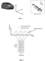
- FIG.2 describes Frequency Modulated Continuous Wave (FMCW) modulation which again is a common type of modulation and would be known to those familiar with the field, although other types of modulation may be used.
- An FMCW waveform also referred to as a chirp, is a complex sinusoidal waveform whose frequency increases linearly with time.
- FMCW radars transmit chirps in a periodic fashion, at a period referred to as the pulse repetition interval (PRI) and most commonly in a sawtooth configuration, although other chirp types are available.
- PRI pulse repetition interval
- the resulting target echo from the scene will contain a delayed and attenuated copy of the transmitted chirp.
- PRI pulse repetition interval
- This waveform is known as the beat signal and its frequency is proportional to the distance to the detected object. Multiple chirps are collected within a single 'frame', which thereby allows determination of doppler frequency changes in the 'slow time' dimension (for velocity determination), and it is these object detections of a frame that are often displayed in a point cloud.
- the estimation of the beat frequency is usually implemented in the digital domain, after the beat signal has been digitally sampled. Since the beat frequency is much smaller than the radar bandwidth, a low-speed analogue-to-digital converter (ADC) can be used. By sampling the beat signal and placing the samples for each chirp into separate columns of a matrix, the row indices of the matrix will correspond to the 'fast' time taken across a single chirp and the column indices will correspond to the 'slow' time taken across multiple chirps.
- ADC analogue-to-digital converter
- the range of the object is determined through detection of the beat frequency, and by applying a further FFT along the rows of the matrix, the velocity of the object can be determined through detection of the doppler frequency.
- FFT Fast Fourier Transform
- the use of these two FFTs is commonly named a 2D FFT and allows objects to be determined in both range and velocity.
- a concomitant benefit of performing the 2D FFT is that it lowers the noise floor or 'background' noise through matched filtering of the object's beat and doppler frequencies.
- the number of objects that fall into the same range-velocity bin will typically be small in number, depending on the range and velocity resolution of the radar.
- FIG.3 illustrates taking instantaneous range-velocity plots at each of the receive ports (including those both real and virtual) and performing a 3 rd 'angle' FFT or 3D FFT. Note that this typically occurs following on from the Constant False Alarm Rate (CFAR) thresholding step, whereby only bins with a Signal-to-Noise (which is the difference of the signal level received by the radar and the background noise) that exceeds a certain threshold are retained. This removes a lot of clutter that would otherwise be present in point cloud displays.
- CFAR Constant False Alarm Rate
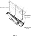
- FIG.4 illustrates the process of point cloud or point set registration and is the process of finding a transformation in space (i.e., by translation and/or rotation) that aligns two point clouds.
- the calculated translation and rotation values may be used to determine the velocity of the ego-vehicle and change in heading angle, or yaw rate, of the ego-vehicle, respectively.
- point cloud registration may be used for calculation of sensor extrinsic positions and angles, without requiring measurement of extrinsic values for every sensor, thereby enabling merging of multiple datasets, which have their own coordinates aligned to each sensor, into a single coordinate system.
- Point cloud registration therefore may be used in autonomous driving systems for applications such as ego-vehicle motion estimation and simultaneous localisation and mapping (SLAM), among others.
- SLAM simultaneous localisation and mapping
- the velocity of the ego-vehicle may be calculated using several means, for instance via readings from in-car sensors through the CAN bus, the doppler shift in the radar data or from the GNSS measurement of velocity.
- the yaw rate of the ego-vehicle is, by definition, the rate of change of the vehicle's heading angle measured in degrees per second, or radians per second, of rotation about a vertical axis through the vehicle's centre of gravity. It may be calculated using a yaw-rate sensor, which is a gyroscopic device that measures a vehicle's yaw rate, or by using GNSS heading measurements. To calculate the heading using GNSS requires a GNSS system that has two GNSS antennas.
- Point cloud registration is one such method of calculating ego-vehicle velocity and yaw rate. Due to a lack of absolute position measurements, it does mean that 'dead reckoning' must be employed. Dead reckoning is the process of calculating the current position of a moving object, by using a previously determined position, and incorporating estimates of velocity, direction (or angle), and elapsed time. The dead-reckoning method is valid for use in accumulating stationary point cloud detections over a short period of time, for instance over a period of several seconds, for the purpose of autonomous driving or robotics applications such as free space detection and occupancy grid mapping, which aim to determine the unoccupied areas of space in front of the ego-vehicle, such that collisions may be avoided.
- Another solution includes Registration with Existing Radar Maps. These systems register a current radar point cloud, or window of several radar point clouds, with an existing radar point cloud-based map, which may have been obtained over multiple vehicle passes.
- a major drawback of this approach is the need for prior maps to have been generated, which may be time-consuming, while also requiring real-time computation.
- other sensors such as IMU and GNSS, are commonly used, which adds cost and reduces reliability in cases where these sensors are not producing reliable data.
- Yet another solution includes feature extraction and iterative closest surface point.
- This method uses filtering to extract key features of the radar point cloud through only keeping the strongest range returns for each Azimuth angle, calculating surface points and normals from the filtered point cloud and then registering with closest surface points and normals in location and angle within a sliding window of previous point cloud frames.
- This method requires no existing map data and can be operated at a relatively high frame rate, however for best performance, parameters need to be optimised for the specific radar sensor parameters and environment.
- FIG. 5 shows this method, where the sinusoidal relationship between the radial velocity and azimuth angle of radar point cloud detections from stationary objects is used to enable the ego-vehicle velocity and yaw rate to be determined. If a radar sensor is moved from its point of view, from the perspective of the radar all stationary targets move in the opposite direction to that of the radar. The velocity relative to the radar of the stationary targets may be calculated using the sensor's velocity and heading direction. However, it is not possible to directly extract the velocity vectors of the targets as a Doppler radar can only measure the radial velocity component.
- range-azimuth static heatmaps for estimating angular movement of an ego-vehicle.
- the range-azimuth static heatmap shows the magnitude of the receive signal from static targets in each range/azimuth bin and therefore has number of pixels equal to the product of the number of range bins and the number of azimuth bins.
- images generated based on static heat maps include noise and side lobes.
- the range-azimuth static heatmap shows the magnitude of the receive signal from static targets in each range/azimuth bin and therefore has number of pixels equal to the product of the number of range bins and the number of azimuth bins.
- a method for estimating angular movement of an ego-vehicle includes measuring and recording radar point clouds of observed detections of static points from a pair of consecutive frames including a previous and a current frame, transforming the radar point cloud from the previous frame to that of the current frame using a transformation matrix, to generate a transformed point cloud, wherein the radar point cloud of the current frame is a current point cloud, converting the transformed point cloud and the current point cloud to corresponding images with pixels that have a signal-to-noise level greater than a predefined level, comparing the images with their differences numerically evaluated, to generate a first error function, adjusting a rotation angle in the transformation matrix till the first error function is minimized, and estimating an inter-frame rotation angle between the consecutive frames, based on the minimized first error function.
- the transformation matrix includes a single variable as yaw angle or rotation angle about the z-axis, by setting the displacement of the ego-vehicle along x and y axes, in terms of frame rate, detected velocity of the ego-vehicle, and yaw or rotation angle about the z-axis.
- the method includes further translating the transformed point cloud using a second transformation matrix, wherein the second transformation matrix includes a single variable as pitch angle or rotation about the y-axis, by setting the displacement of the ego-vehicle along x and z axes, in terms of the frame rate, detected velocity and pitch angle or rotation about the y-axis; converting the further transformed point cloud and the current point cloud to corresponding images with pixels that have a signal-to-noise level larger than a predefined level; comparing the images with their differences numerically evaluated, to generate a second error function; minimising the second error function by adjusting the pitch angle or rotation angle about the y-axis for the estimated pitch angle; and estimating the pitch angle or rotation about the y-axis based on the minimized second error function.
- the second transformation matrix includes a single variable as pitch angle or rotation about the y-axis, by setting the displacement of the ego-vehicle along x and z axes, in terms of the frame rate, detected velocity and pitch angle
- the magnitude of the difference between the pixels of two images are summed to generate first or second error functions.
- the transformation matrix is generated based on two variables of pitch and yaw angles
- the first error function includes a 2-dimensional error matrix that is minimized by adjustment of both the yaw and pitch angles.
- the displacements in x, y and z axes in the transformation matrix are set in terms of the frame rate, yaw angle, pitch angle and detected velocity.
- an offset number k of frames is used and k is greater than 1.
- the method includes applying a digital filter to the transformed point cloud or further transformed point cloud to reduce the point cloud noise.
- the detected velocity is the unambiguous velocity.
- the rotation angle is one of: pitch angle or yaw angle.
- a system for estimating angular movement of an ego-vehicle includes a memory to store one or more instructions, and a processor to execute the one or more instructions to: measure and record radar point clouds of observed detections of static points from consecutive frames; transform the radar point cloud from a previous frame to that of a current frame using a transformation matrix, to generate a transformed point cloud, wherein the radar point cloud of the current frame is a current point cloud; convert the transformed point cloud and the current point cloud to corresponding images with pixels that have a signal-to-noise level greater than a predefined level; compare the images with their differences numerically evaluated, to generate a first error function; adjust a rotation angle in the transformation matrix till the first error function is minimized; and estimate an inter-frame rotation angle between the consecutive frames, based on the minimized first error function.
- Various embodiments of the present invention use point cloud measurements from an automotive radar, over consecutive or a fixed number of frames, to calculate the transformation parameters required to map the points acquired from the first frame onto those acquired from the second frame.
- the transformation parameters are thereafter used to estimate yaw rate and movement from the radar point cloud.
- the present invention works with any imaging radar point cloud and is more robust as only detection peaks are examined. Also, the method and system of the present invention eliminates the need of using static radar heatmaps.
- Embodiments of the present invention eliminate the need of a GNSS receiver or alternative in a sensor system that uses ego-vehicle velocity and yaw rate for the purpose of free-space detection or occupancy grid mapping only, i.e., where absolute position measurements are not required, as accumulation of stationary target detections over several frames (for instance over 250 to 500 milliseconds duration). They provide an ability to track location when underground or in built up areas where GNSS satellite visibility is limited, thereby offering redundancy to other sensor systems on the ego-vehicle, and reduced reliance on the accurate extrinsic calibration of sensors in the calculation of ego-vehicle yaw rate, as this parameter is removed from the calculation.
- the invention can be used in any radar system, including those for applications such as defence or warfare, but is more specifically applicable for automotive applications. It is noted that in these applications, the pitch movement is small or non-existent, so the pitch extension calculation may not be required.
- a computer program comprising program instructions for causing a computer program to carry out the above method which may be embodied on a record medium, carrier signal or read-only memory.
- FIG.5 illustrates the sinusoidal relationship between the measured radial velocity (calculated in the 2D FFT step) and azimuth angle (calculated in the 3D FFT step or subsequent angle processing step) of the stationary radar point cloud detections.
- the detections from dynamic targets, multipath or low SNR targets may not be located on this trendline, hence a clustering technique such as RANSAC (Random Sample Consensus) or DBSCAN (Density-Based clustering) may be used to only retain stationary points.
- RANSAC Random Sample Consensus
- DBSCAN Density-Based clustering
- the sensor velocity magnitude, v s , and angle, ⁇ may then be calculated as shown below, where r d , the relative radar direction, is equal to 1 for a forward-facing radar and -1 for a backward-facing radar.
- FIG.6 illustrates the location of the radar relative to the ego-vehicle's rear axle (b and I) and the radar mounting angle ( ⁇ ) are also used in calculating the ego-vehicle velocity and yaw rate from the sensor velocity magnitude/ angle meaning that an accurate extrinsic calibration is needed.
- This is a significant disadvantage in practice for calculating the ego-vehicle yaw rate as even small variations in the extrinsic parameters ( ⁇ , b or I) can lead to large errors.
- the detected velocity is the unambiguous velocity and is calculated from a small phase change in the returned signal. Trigonometry functions obviously give the same value if calculated at e.g. 360/720 etc. degrees. An ambiguous velocity could be the velocity recovered from a number of these different phases.
- Reference source not found is a flowchart illustrating a method of estimating angular movement of an ego-vehicle between consecutive frames, in accordance with an embodiment of the present invention.
- radar point clouds are measured and recorded from observed detection peaks of stationary points from a known number of consecutive or latest frames. If dead reckoning for location tracking is being employed, the last known location measurement (from a GNSS receiver) is recorded, otherwise an arbitrary location starting point is chosen. It is to be noted that the detection points for dynamic, or moving objects, are removed / ignored from the point cloud(s). As points from dynamic or moving objects are removed, the changes in the point cloud are only due to changes in the viewpoint of the radar relative to the static points in the scenes. The removal of the dynamic points means that the change in viewpoint can only be due to the motion and yaw turn of the ego-vehicle.
- point clouds would be typical of the outputs from an automotive radar that have been fully processed using digital signal processing. Since such point clouds only contain detection information above a pre-defined threshold, a static heat map (which is a graphical display or image of all information with all signal levels in the scene usually represented by a colour scale) cannot be formed and the calculations in the described invention are quicker due to redundant information not being present in the point cloud. Furthermore, the described invention is therefore applicable to all automotive radar outputs and is not reliant on the ability to access lower-level detection data.
- the point cloud from a known earlier frame is transformed to that of the current frame using a transformation matrix with a given rotation angle.
- the transformation matrix is applied to the X, Y and Z coordinates of the radar point cloud from a previously captured frame, to generate a transformed point cloud.
- the point cloud of a current frame is hereinafter referred to as current point cloud.
- the transformation matrix is a 3D affine transformation matrix that is generated for static points in the point cloud using an unknown rotation angle, known frame rate and calculated ego-vehicle velocity.
- an accurate estimate of the ego-vehicle velocity can be obtained from the prior art methods, such as that of Kellner et al, whereby the ego-car velocity may be extracted from the trendline of radial velocity versus azimuth angle detections in the point cloud, shown in Error! Reference source not found..
- the frame rate is a known quantity
- the yaw rate between frames can be determined and therefore yaw rate in radians per second can be calculated.
- the transformation matrix is dependent on only one unknown variable, i.e., yaw angle ⁇ .
- the parameters of equation (16) are independent of the mounting angle or the reference coordinate system, and only relies on the relative changes between measurements taken from the same sensor over a period of time, provided the mounting position and angle of the sensor are unchanged within this time. This means that the reliance on the accuracy of the extrinsic calibration (one of the most restricting factors of existing methods) is removed.
- the point cloud from a previous frame, or a fixed offset number of earlier frames may be transformed to the transformed point cloud according to the transformation matrix of equation (16), using the previously calculated or recorded values for velocity (v) and inter-frame rate (FPS I ).
- FPS I is equal to the frame rate divided by the offset number of frames used. For instance, if a comparison is made between the current frame and the previous frame the values of FPS and FPS I would be equal, but if comparison is made between the current frame and five frames previous, FPS I would be one fifth of FPS.
- an initial value of the rotation angle ⁇ may be chosen based on the maximum angular rotation that is realistic within the inter-frame time - note that this may also be refined based on calculated rotation angle values from previous frames.
- a typical starting value for the inter-frame rotation angle, ⁇ is -3 degrees. The value used depends on the maximum expected angular velocity magnitude in degrees per frame that is expected.
- the transformed point cloud and the current point cloud are converted to transformed and current images respectively, with pixels only registered that have a signal-to-noise level larger than a predefined level.
- a predefined level In an embodiment, an identical number of pixels are present in each image, for instance 256 x 256.
- This conversion to image form is made by performing a grid-search to find detections that are within pre-defined pixels.
- the pixels that contain detections are set to the sum of the signal-to-noise ratio in dB for these detections while pixels that do not are set to 0 dB. In this way, further redundant information is removed from the images in addition to that already removed by the digital signal processing of the detection data.
- the transformed and current images are compared and their differences are numerically evaluated, to generate an error function.
- the correspondence between transformed and current point clouds is determined by comparing these images and is given a value in the form of an error function.
- a variety of methods exist to calculate this error can include calculating the difference between corresponding pixel magnitudes in the transformed and current point clouds or alternatively on a multiplication of the corresponding pixel magnitudes in the transformed and current point clouds.
- step 710 it is checked if the error function is minimum.
- the error function may be minimized by adjustment of the rotation angle in the transformation matrix.
- the rotation angle is one of yaw angle or in other embodiments, the pitch angle.
- the rotation angle is adjusted and the process restarts from step 704 for the transformation matrix with adjusted rotation angle.
- Several approaches can be taken to find the value for ⁇ for which the minimum error function value occurs.
- One approach is to use an incremental step function whereby the error function is evaluated from a low value of ⁇ to a high value of ⁇ (e.g., -3 to +3 degrees) in small steps (of 0.1 degrees), with the correct value being the one that gives the lowest error function value.
- a coarse angle step may be used initially to estimate approximate the ⁇ value at which the minimum error function value occurs and then a fine angle step used to refine this estimate further.
- an inter-frame rotation angle ⁇ is estimated between the known number of frames, corresponding to the minimum error function.
- the inter-frame rotation angle is the rotation angle per inter-frame interval.
- the yaw-rate of the vehicle may be estimated using the recorded value for the inter-frame rate (FPS I ).
- FPS I inter-frame rate
- two approaches for reducing yaw rate estimation noise may be used in alignment with the described invention. Both may be used separately or concurrently.
- the first approach calculates the yaw angle by comparing the point cloud with a window of frames, rather than just the previous frame; for instance a window of five frames could be used, with the limit on a realistic window size being the processing time required and the difficulty in achieving good correspondence between the hypothesis and current point clouds if the window size is too large, i.e., if features within the scene change too significantly within the window time.
- the inter-frame rotation angle for each comparison within the window may be normalised to a per-frame rotation angle and the calculated values for this within the window averaged.
- the second approach uses a digital filter such as a constant-velocity model Kalman filter (where the object is assumed to move with a nearly constant velocity) to reduce these calculation errors.
- a digital filter such as a constant-velocity model Kalman filter (where the object is assumed to move with a nearly constant velocity)
- four parameters may be used to represent the position and velocity in the X and Y dimensions.
- the calculated x and y components of velocity, derived from the velocity magnitude and yaw rate calculations, may be used to compare with predicted values.
- Kalman filter parameters such as spectral density and x/y velocity standard deviation may determine the performance of the filter and is dependent on the application and the type of sensor used, so these details are not discussed here.
- the transformation in the XZ plane can be further applied to estimate if the pitch of the vehicle has changed e.g. by climbing a hill, (as shown in FIG.9 ).
- this calculated pitch angle as in the case of the yaw angle, only refers to the change in pitch between the first and second point clouds.
- the calculation should be referenced to the previous pitch angle, along with all other pitch angle calculations from the last known pitch angle.
- the current pitch angle deviation from the last known pitch angle will be the sum of each of the previous pitch angle calculations from the last known pitch angle.
- the point cloud may be accumulated across the window of frames with calculated ego-velocity (from Kellner et al method) and a parameterised yaw rate value (which can be swept through a defined range of angles); the error function value for the optimisation is in this case the number of occupied pixels in the accumulated point cloud image across a window of frames. This makes use of how the accumulated point cloud 'smears' when an incorrect yaw rate is applied during the accumulation.
- One limitation of those method is that it assumes a constant yaw rate across the accumulated window of frames so depending on the ego-vehicle speed this may not be valid and hence the method may be more suited to situations with slow ego-vehicles, such as in robotics applications like mining.
Landscapes
- Engineering & Computer Science (AREA)
- Remote Sensing (AREA)
- Radar, Positioning & Navigation (AREA)
- Physics & Mathematics (AREA)
- Computer Networks & Wireless Communication (AREA)
- General Physics & Mathematics (AREA)
- Electromagnetism (AREA)
- Signal Processing (AREA)
- Radar Systems Or Details Thereof (AREA)
Priority Applications (2)
| Application Number | Priority Date | Filing Date | Title |
|---|---|---|---|
| EP23212929.6A EP4564056A1 (de) | 2023-11-29 | 2023-11-29 | System und verfahren zur implementierung von odometrie unter verwendung von radarpunktwolkenregistrierung |
| PCT/EP2024/084008 WO2025114491A1 (en) | 2023-11-29 | 2024-11-28 | System and method of implementing odometry using radar point cloud |
Applications Claiming Priority (1)
| Application Number | Priority Date | Filing Date | Title |
|---|---|---|---|
| EP23212929.6A EP4564056A1 (de) | 2023-11-29 | 2023-11-29 | System und verfahren zur implementierung von odometrie unter verwendung von radarpunktwolkenregistrierung |
Publications (1)
| Publication Number | Publication Date |
|---|---|
| EP4564056A1 true EP4564056A1 (de) | 2025-06-04 |
Family
ID=89029616
Family Applications (1)
| Application Number | Title | Priority Date | Filing Date |
|---|---|---|---|
| EP23212929.6A Ceased EP4564056A1 (de) | 2023-11-29 | 2023-11-29 | System und verfahren zur implementierung von odometrie unter verwendung von radarpunktwolkenregistrierung |
Country Status (2)
| Country | Link |
|---|---|
| EP (1) | EP4564056A1 (de) |
| WO (1) | WO2025114491A1 (de) |
Citations (2)
| Publication number | Priority date | Publication date | Assignee | Title |
|---|---|---|---|---|
| US20140376821A1 (en) * | 2011-11-07 | 2014-12-25 | Dimensional Perception Technologies Ltd. | Method and system for determining position and/or orientation |
| US20220144305A1 (en) * | 2019-10-16 | 2022-05-12 | Yuan Ren | Method and system for localization of an autonomous vehicle in real-time |
-
2023
- 2023-11-29 EP EP23212929.6A patent/EP4564056A1/de not_active Ceased
-
2024
- 2024-11-28 WO PCT/EP2024/084008 patent/WO2025114491A1/en active Pending
Patent Citations (2)
| Publication number | Priority date | Publication date | Assignee | Title |
|---|---|---|---|---|
| US20140376821A1 (en) * | 2011-11-07 | 2014-12-25 | Dimensional Perception Technologies Ltd. | Method and system for determining position and/or orientation |
| US20220144305A1 (en) * | 2019-10-16 | 2022-05-12 | Yuan Ren | Method and system for localization of an autonomous vehicle in real-time |
Non-Patent Citations (3)
| Title |
|---|
| BARJENBRUCH MICHAEL ET AL: "Joint spatial- and Doppler-based ego-motion estimation for automotive radars", 2015 IEEE INTELLIGENT VEHICLES SYMPOSIUM (IV), IEEE, 28 June 2015 (2015-06-28), pages 839 - 844, XP033209780, DOI: 10.1109/IVS.2015.7225789 * |
| LU CHRIS XIAOXUAN ET AL: "milliEgo single-chip mmWave radar aided egomotion estimation via deep sensor fusion", PROCEEDINGS OF THE 2020 ACM SIGSIM CONFERENCE ON PRINCIPLES OF ADVANCED DISCRETE SIMULATION, ACMPUB27, NEW YORK, NY, USA, 16 November 2020 (2020-11-16), pages 109 - 122, XP058728476, ISBN: 978-1-4503-7592-4, DOI: 10.1145/3384419.3430776 * |
| MONACO CHRISTOPHER D: "Ego-Motion Estimation from Doppler and Spatial Data in Sonar, Radar, or Camera Images", 31 December 2019 (2019-12-31), XP093069016, ISBN: 979-8-8193-9286-7, Retrieved from the Internet <URL:https://www.proquest.com/docview/2674697659?pq-origsite=gscholar&fromopenview=true> [retrieved on 20230731] * |
Also Published As
| Publication number | Publication date |
|---|---|
| WO2025114491A1 (en) | 2025-06-05 |
Similar Documents
| Publication | Publication Date | Title |
|---|---|---|
| EP3252501B1 (de) | Verbesserte objekterkennung und bewegungsstatusschätzung für ein fahrzeugumgebungserkennungssystem | |
| CN110320515B (zh) | 用于测试目标物体作为单点散射中心的方法 | |
| US7038612B2 (en) | Method for SAR processing without INS data | |
| EP3104189B1 (de) | Fehlausrichtungsschätzung für ein kraftfahrzeugradarsystem | |
| CN116507940A (zh) | 用于雷达信号的信号处理的方法、雷达系统和车辆 | |
| CN114814761B (zh) | 用于车辆自我运动估计的雷达数据处理 | |
| US20190180451A1 (en) | Enhanced object detection and motion estimation for a vehicle environment detection system | |
| Barjenbruch et al. | Joint spatial-and Doppler-based ego-motion estimation for automotive radars | |
| EP3775989B1 (de) | Vorrichtung, system und verfahren zur lokalisierung eines ziels in einer szene | |
| US5327140A (en) | Method and apparatus for motion compensation of SAR images by means of an attitude and heading reference system | |
| CN114814762B (zh) | 用于车辆自我运动估计的雷达数据处理 | |
| US11092686B2 (en) | Method, apparatus and device for doppler compensation in a time switched MIMO radar system | |
| US9846229B1 (en) | Radar velocity determination using direction of arrival measurements | |
| EP3367121B1 (de) | Radar mit inverser synthetischer apertur für ein radarsystem eines kraftfahrzeugs | |
| US20240140504A1 (en) | Orientation-based position determination for rail vehicles | |
| CN111712722B (zh) | 借助雷达传感器估计点目标的横向速度或笛卡尔速度 | |
| CN116182905B (zh) | 激光雷达和组合惯导的时空外参标定方法、装置及系统 | |
| CN113534125B (zh) | 一种估算目标模糊速度的方法 | |
| EP1504283A1 (de) | Verfahren und vorrichtung zur geländekorrelation | |
| US11859979B2 (en) | Delta position and delta attitude aiding of inertial navigation system | |
| Lindstrom et al. | GPS-denied navigation aided by synthetic aperture radar using the range-Doppler algorithm | |
| CN114594466A (zh) | 用于确定目标的自有速度估计值和角度估计值的方法 | |
| CN112904339A (zh) | 斜距历程与航向交点表征的双基前视sar成像方法 | |
| EP4564056A1 (de) | System und verfahren zur implementierung von odometrie unter verwendung von radarpunktwolkenregistrierung | |
| CN119916312B (zh) | 毫米波雷达-imu的外参标定方法、装置、设备及存储介质 |
Legal Events
| Date | Code | Title | Description |
|---|---|---|---|
| PUAI | Public reference made under article 153(3) epc to a published international application that has entered the european phase |
Free format text: ORIGINAL CODE: 0009012 |
|
| STAA | Information on the status of an ep patent application or granted ep patent |
Free format text: STATUS: THE APPLICATION HAS BEEN PUBLISHED |
|
| AK | Designated contracting states |
Kind code of ref document: A1 Designated state(s): AL AT BE BG CH CY CZ DE DK EE ES FI FR GB GR HR HU IE IS IT LI LT LU LV MC ME MK MT NL NO PL PT RO RS SE SI SK SM TR |
|
| STAA | Information on the status of an ep patent application or granted ep patent |
Free format text: STATUS: THE APPLICATION HAS BEEN REFUSED |
|
| 18R | Application refused |
Effective date: 20250616 |