EP4564744A1 - Verfahren und system zum sammeln von durch intelligente zähler gemessenen verbrauchsdaten - Google Patents
Verfahren und system zum sammeln von durch intelligente zähler gemessenen verbrauchsdaten Download PDFInfo
- Publication number
- EP4564744A1 EP4564744A1 EP24215605.7A EP24215605A EP4564744A1 EP 4564744 A1 EP4564744 A1 EP 4564744A1 EP 24215605 A EP24215605 A EP 24215605A EP 4564744 A1 EP4564744 A1 EP 4564744A1
- Authority
- EP
- European Patent Office
- Prior art keywords
- smart meter
- type
- information system
- data
- consumption data
- Prior art date
- Legal status (The legal status is an assumption and is not a legal conclusion. Google has not performed a legal analysis and makes no representation as to the accuracy of the status listed.)
- Granted
Links
Images


Classifications
-
- G—PHYSICS
- G01—MEASURING; TESTING
- G01D—MEASURING NOT SPECIALLY ADAPTED FOR A SPECIFIC VARIABLE; ARRANGEMENTS FOR MEASURING TWO OR MORE VARIABLES NOT COVERED IN A SINGLE OTHER SUBCLASS; TARIFF METERING APPARATUS; MEASURING OR TESTING NOT OTHERWISE PROVIDED FOR
- G01D4/00—Tariff metering apparatus
- G01D4/002—Remote reading of utility meters
- G01D4/004—Remote reading of utility meters to a fixed location
-
- H—ELECTRICITY
- H04—ELECTRIC COMMUNICATION TECHNIQUE
- H04L—TRANSMISSION OF DIGITAL INFORMATION, e.g. TELEGRAPHIC COMMUNICATION
- H04L9/00—Cryptographic mechanisms or cryptographic arrangements for secret or secure communications; Network security protocols
- H04L9/08—Key distribution or management, e.g. generation, sharing or updating, of cryptographic keys or passwords
- H04L9/0816—Key establishment, i.e. cryptographic processes or cryptographic protocols whereby a shared secret becomes available to two or more parties, for subsequent use
- H04L9/0819—Key transport or distribution, i.e. key establishment techniques where one party creates or otherwise obtains a secret value, and securely transfers it to the other(s)
- H04L9/0825—Key transport or distribution, i.e. key establishment techniques where one party creates or otherwise obtains a secret value, and securely transfers it to the other(s) using asymmetric-key encryption or public key infrastructure [PKI], e.g. key signature or public key certificates
-
- H—ELECTRICITY
- H04—ELECTRIC COMMUNICATION TECHNIQUE
- H04L—TRANSMISSION OF DIGITAL INFORMATION, e.g. TELEGRAPHIC COMMUNICATION
- H04L63/00—Network architectures or network communication protocols for network security
- H04L63/04—Network architectures or network communication protocols for network security for providing a confidential data exchange among entities communicating through data packet networks
- H04L63/0428—Network architectures or network communication protocols for network security for providing a confidential data exchange among entities communicating through data packet networks wherein the data content is protected, e.g. by encrypting or encapsulating the payload
- H04L63/0442—Network architectures or network communication protocols for network security for providing a confidential data exchange among entities communicating through data packet networks wherein the data content is protected, e.g. by encrypting or encapsulating the payload wherein the sending and receiving network entities apply asymmetric encryption, i.e. different keys for encryption and decryption
-
- H—ELECTRICITY
- H04—ELECTRIC COMMUNICATION TECHNIQUE
- H04L—TRANSMISSION OF DIGITAL INFORMATION, e.g. TELEGRAPHIC COMMUNICATION
- H04L9/00—Cryptographic mechanisms or cryptographic arrangements for secret or secure communications; Network security protocols
- H04L9/40—Network security protocols
-
- H—ELECTRICITY
- H04—ELECTRIC COMMUNICATION TECHNIQUE
- H04W—WIRELESS COMMUNICATION NETWORKS
- H04W12/00—Security arrangements; Authentication; Protecting privacy or anonymity
- H04W12/03—Protecting confidentiality, e.g. by encryption
- H04W12/033—Protecting confidentiality, e.g. by encryption of the user plane, e.g. user's traffic
-
- H—ELECTRICITY
- H04—ELECTRIC COMMUNICATION TECHNIQUE
- H04W—WIRELESS COMMUNICATION NETWORKS
- H04W12/00—Security arrangements; Authentication; Protecting privacy or anonymity
- H04W12/50—Secure pairing of devices
-
- G—PHYSICS
- G01—MEASURING; TESTING
- G01D—MEASURING NOT SPECIALLY ADAPTED FOR A SPECIFIC VARIABLE; ARRANGEMENTS FOR MEASURING TWO OR MORE VARIABLES NOT COVERED IN A SINGLE OTHER SUBCLASS; TARIFF METERING APPARATUS; MEASURING OR TESTING NOT OTHERWISE PROVIDED FOR
- G01D2204/00—Indexing scheme relating to details of tariff-metering apparatus
- G01D2204/40—Networks; Topology
-
- H—ELECTRICITY
- H04—ELECTRIC COMMUNICATION TECHNIQUE
- H04L—TRANSMISSION OF DIGITAL INFORMATION, e.g. TELEGRAPHIC COMMUNICATION
- H04L67/00—Network arrangements or protocols for supporting network services or applications
- H04L67/01—Protocols
- H04L67/12—Protocols specially adapted for proprietary or special-purpose networking environments, e.g. medical networks, sensor networks, networks in vehicles or remote metering networks
-
- H—ELECTRICITY
- H04—ELECTRIC COMMUNICATION TECHNIQUE
- H04Q—SELECTING
- H04Q2209/00—Arrangements in telecontrol or telemetry systems
- H04Q2209/60—Arrangements in telecontrol or telemetry systems for transmitting utility meters data, i.e. transmission of data from the reader of the utility meter
-
- H—ELECTRICITY
- H04—ELECTRIC COMMUNICATION TECHNIQUE
- H04Q—SELECTING
- H04Q9/00—Arrangements in telecontrol or telemetry systems for selectively calling a substation from a main station, in which substation desired apparatus is selected for applying a control signal thereto or for obtaining measured values therefrom
-
- H—ELECTRICITY
- H04—ELECTRIC COMMUNICATION TECHNIQUE
- H04W—WIRELESS COMMUNICATION NETWORKS
- H04W88/00—Devices specially adapted for wireless communication networks, e.g. terminals, base stations or access point devices
- H04W88/02—Terminal devices
- H04W88/04—Terminal devices adapted for relaying to or from another terminal or user
Definitions
- At least one embodiment relates to a method and a system for collecting consumption data measured by a smart meter.
- the system in question is suitable for collecting such data from several smart meters, whether for fluid consumption measurements (such as gas, water, heat, gasoline) or electricity consumption measurements.
- Smart meters such as electricity meters (electricity consumption meters) or fluid meters (fluid consumption meters), are known and include communication interfaces allowing an automated management system to remotely collect consumption data.
- smart electricity meters include a Powerline Communications (PLC) type communication interface.
- PLC Powerline Communications
- Consumption data can thus be transmitted, at regular or irregular intervals, to an information system (IS) which processes them centrally.
- IS information system
- each information system remains in control of the consumption data from the smart meters that concern them.
- the information systems do not have to exchange information with each other, even though they share the same network infrastructure (communications network, data concentrator).
- Asymmetric encryption ensures non-repudiation of data.
- each smart meter of the second type operates on batteries, and the smart meter of the first type serving as a relay for the smart meter of the second type in question programs standby exit times of the smart meter of the second type in question to obtain the second consumption data to be relayed via the communication network.
- consumption data of smart meters operating on batteries are easily collected.
- At least one smart meter of the first paired type operates on batteries, and the smart meter of the first type in question programs its own standby exit times, so as to be taken out of standby when each smart meter of the second type paired with the smart meter of the first type in question comes out of standby.
- the batteries of the smart meters of the first paired type are preserved as best as possible with regard to the collection of consumption data from the smart meters of the second type.
- each smart meter of the second type communicates securely by symmetric encryption with the paired smart meter of the first type which serves as its relay, the smart meter of the first type in question obtaining a symmetric encryption key to be used with the smart meter of the second type in question from the second information system.
- the symmetric encryption complements the asymmetric encryption to provide more security.
- each smart meter of the second type provides the paired smart meter of the first type which serves as its relay with an address of a piece of equipment of the second information system from which to obtain the key of symmetric encryption for use with the second type smart meter in question.
- each smart meter of the first type communicates securely by symmetric encryption with the data concentrator, the data concentrator obtaining a symmetric encryption key for use with the smart meter of the first type in question from the first information system.
- the symmetric encryption complements the asymmetric encryption to provide more security.
- FIG. 1A schematically illustrates an automated management system 100 in which the present invention can be implemented.
- the automated management system 100 is configured to carry out a collection of consumption data from measurements carried out by smart meters 150, 150a, 150b, 150c.
- the collected consumption data are processed by several information systems (IS) that share the same collection infrastructure.
- Each information system is dedicated to a group of smart meters.
- a first information system IS1 110a is dedicated to processing consumption data from a group of smart electricity meters
- a second information system IS2 110b is dedicated to processing consumption data from a group of smart water meters
- a third information system IS3 110c is dedicated to processing consumption data from a group of smart gas meters.
- the information systems IS1 110a, IS2 110b and IS3 110c are managed by separate operators and are dedicated to processing consumption data from respective groups of smart fluid meters (water, gas or other) that have subscribed to their respective operators.
- the information systems IS1 110a, IS2 110b and IS3 110c delegate the collection of consumption data to data concentrators DC (Data Concentrator) 120, so as to distribute the collection load.
- Each data concentrator DC 120 thus manages a first communication network NET1 101 which serves as a collection network.
- Each data concentrator DC 120 thus serves as a relay between smart meters and the information systems IS1 110a, IS2 110b and IS3 110c.
- each data concentrator DC 120 directs consumption data received through the first communication network NET1 101 from a said smart meter, to one or other of the information systems IS1 110a, IS2 110b, according to secure links established in the collection system 100.
- each DC 120 data concentrator is external to the IS1 110a, IS2 110b and IS3 110c information systems and communicates with the IS1 110a, IS2 110b and IS3 110c information systems via a second NET2 102 communication network.
- a first type of smart meters which we could call “smart meters” primary » PSMs (Primary Smart Meters), which are able to communicate via the first communication network NET1 101 and thus directly transmit their consumption data to the data concentrator DC 120 managing the first communication network NET1 101; and a second type of smart meters, which could be called “secondary smart meters” SSMs (Secondary Smart Meters), which are not able to communicate via the first communication network NET1 101 and then transmit their consumption data to the data concentrator DC 120 managing the first communication network NET1 101 by relying on a said first-type smart meter serving as a relay.
- PSMs Primary Smart Meters
- SSMs Secondary Smart Meters
- a said DC 120 data concentrator manages the collection of consumption data on behalf of the IS2 110b information system.
- the smart meters concerned by this collection include a SM2 150b smart meter (which is a secondary SSM smart meter).
- Said DC 120 data concentrator also manages the collection of consumption data on behalf of the IS3 110c information system.
- the smart meters concerned by this other collection include a SM3 150c smart meter (which is a secondary SSM smart meter).
- Said DC 120 data concentrator finally manages the collection of consumption data on behalf of the IS1 110a information system.
- the smart meters concerned by this last collection include a SM1 150 smart meter and an eSM1 150a smart meter (which are primary PSM smart meters).
- the eSM1 150a smart meter is an enhanced smart meter, which performs a gateway function on behalf of at least one other smart meter that depends on an IS information system other than the IS1 110a information system on which said eSM1 150a smart meter depends.
- the eSM1 150a smart meter serves as a relay for the SM2 150b and SM3 150c smart meters.
- the first NET1 101 communication network is a PLC (PowerLine Communications) type network, as compliant with the G3-PLC or PRIME specifications.
- the PSM primary smart meters are then smart electricity meters, therefore potentially in full operation at all times.
- the first network of NET1 101 communication is a LPWAN (Low-Power Wide Area network) type wireless network as found in the Internet of Things (IoT).
- the primary PSM smart meters can then be smart fluid meters (water, gas or other), typically powered by batteries, and therefore with intermittent operation (standby periods) in order to preserve said batteries.
- the second communication network NET2 102 is a 5G ( 5th Generation) wireless communication network.
- the communication network NET2 102 is a GPRS (General Packet Radio Service), UMTS (Universal Mobile Telecommunication System) or LTE (Long-Term Evolution) wireless communication network.
- GPRS General Packet Radio Service
- UMTS Universal Mobile Telecommunication System
- LTE Long-Term Evolution
- each secondary smart meter SSM is connected to the primary smart meter PSM which acts as a relay using a communication link compliant with the M-Bus remote reading specifications (“Meter Bus” in English), as defined in the EN 13757-2 standard, or the wM-Bus specifications (“Wireless M-Bus” in English), as defined in the EN 13757-4 standard.
- M-Bus remote reading specifications (“Meter Bus” in English)
- wM-Bus specifications Wireless M-Bus” in English
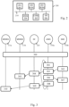
- Fig. 1B schematically illustrates an arrangement of the IS information system 110 (to which correspond the information systems IS1 110a, IS2 110b and IS3 110c), in a particular embodiment.
- the IS information system 110 comprises various components including a head-end system HES (Head-End System) 112, a meter data management system MDMS (Meter Data Management System) 111, and a key management system KMS (Key Management System) 113.
- HES Head-End System
- MDMS Metal Data Management System
- KMS Key Management System
- the components of the IS 110 information system communicate, for example, using the Internet, or more generally an IP (Internet Protocol) type network, or potentially using a VPN (Virtual Private Network).
- IP Internet Protocol
- VPN Virtual Private Network
- the HES 112 head-end system is configured to perform transmission management as part of consumption data collection.
- the MDMS 111 meter data management system is configured to process the collected consumption data.
- the KMS key management system 113 is configured to store encryption keys required by the smart meters that depend on the IS information system 110 in question.
- the KMS key management system 113 provides the MDMS meter data management system 111 with the keys required for the decryptions that said MDMS meter data management system 111 must perform.
- the KMS key management system of the IS1 110a information system manages the keys necessary for the smart meters which depend on the IS1 110a information system
- the KMS key management system of the IS2 110b information system manages the keys necessary for the smart meters which depend on the IS2 110b information system
- the KMS key management system of the IS3 110c information system manages the keys necessary for the smart meters which depend on the IS3 110c information system.
- the key management system KMS 113 is configured to store asymmetric encryption public keys.
- Each asymmetric encryption public key AK1 corresponds to an asymmetric encryption private key AK2, which is held in the automated management system 100 only by the smart meter in question.
- the asymmetric encryption private key AK2 is for example derived from a serial number of the corresponding smart meter.
- the asymmetric encryption public key AK1 is used to decrypt signed data using the corresponding asymmetric encryption private key AK2.
- Each pair of asymmetric encryption public key AK1 and asymmetric encryption private key AK2 ensures non-repudiation of the consumption data transmitted (measured) by the smart meter in question to the information system IS 110 on which said smart meter depends.
- the KMS 113 key management system is configured to store symmetric encryption keys.
- a first symmetric encryption key SK1 for each secondary smart meter SSM to communicate securely with the primary smart meter PSM which serves as its relay.
- THE Key management system KMS 113 of the IS2 110b information system stores the symmetric encryption key SK1 for each secondary smart meter SSM that depends on said IS2 110b information system, including the SM2 150b smart meter.
- the key management system KMS 113 of the information system IS3 110c stores the symmetric encryption key SK1 for each secondary smart meter SSM which depends on said information system IS3 110c, including the smart meter SM3 150c.
- the key management system KMS 113 of the information system IS1 110a stores the symmetric encryption key SK2 for each primary smart meter PSM which depends on said information system IS1 110a, including the smart meters SM1 150 and eSM1 150a.
- FIG. 2 schematically illustrates an example of hardware architecture 200, which is suitable for implementing any device controller of the automated management system 100.
- the example of hardware architecture is thus suitable for implementing an information system IS controller, or any component of the information system IS.
- the example of hardware architecture is also suitable for implementing a data concentrator controller DC 120.
- the example of hardware architecture is also suitable for implementing a primary smart meter controller PSM.
- the example of hardware architecture is also suitable for implementing a secondary smart meter controller SSM.
- the hardware architecture 200 then comprises, connected by a communication bus 210: a processor or CPU (Central Processing Unit) 201; a RAM (Random Access Memory) 202; a ROM (Read Only Memory) 203, or EEPROM (Electrically Erasable Programmable ROM), or a Flash type memory; a DSM (Data Storage Medium) 204 data storage medium, such as a HDD (Hard Disk Drive), or a storage medium reader, such as an SD (Secure Digital) card reader; and at least one COM communication interface 205.
- the hardware architecture 200 may further comprise I/O 206 inputs/outputs, for example to carry out consumption measurements.
- the processor 201 is capable of executing instructions loaded into the RAM 202 from the ROM 203, from an external memory (not shown), from a storage medium, such as an SD card, or from a communications network.
- the processor 201 is capable of reading instructions from the RAM 202 and executing them. These instructions form a computer program causing the processor 201 to implement the steps and algorithms described herein in relation to the device concerned.
- each device of the automated management system 100 comprises electronic circuitry arranged and configured to implement the steps and algorithms described herein in relation to the device in question.
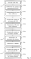
- FIG. 3 schematically illustrates exchanges occurring in the automated management system 100 to collect consumption data.
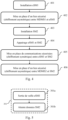
- a step 300 of setting up secure communications and setting up the relay by the eSM1 150a smart meter is carried out. This step 300 is detailed in relation to the Fig. 4 .
- a secure link is established, in a step 402, between the smart meter eSM1 150a and the information system IS1 110a, and more particularly the meter data management system MDMS 111a (labeled MDMS1) of the information system IS1 110a.
- the meter data management system MDMS1 111a retrieves the asymmetric encryption public key associated with the smart meter eSM1 150a from the key management system KMS 113 of the information system IS1 110a.
- the secure link is ensured by activating the asymmetric encryption between the smart meter eSM1 150a and the IS1 110a information system. This secure link is suitable for ensuring non-repudiation of data provided (measured) by the eSM1 150a smart meter and preventing the identity of the eSM1 150a smart meter from being usurped.
- a pairing is carried out between the eSM1 150a smart meter and the SM2 150b smart meter in a step 404.
- a press e.g., a long press
- the eSM1 150a smart meter and the SM2 150b smart meter recognize each other, and configure themselves so that the eSM1 150a smart meter relays data on behalf of the SM2 150b smart meter.
- the eSM1 150a smart meter synchronizes the SM2 150b smart meter temporally and programs a next wake-up time for it.
- the SM2 150b smart meter can then go into standby mode.
- a step 405 in order to complete the pairing between the smart meter eSM1 150a and the smart meter SM2 150b, secure communications, by symmetric encryption, are set up between the smart meter eSM1 150a and the smart meter SM2 150b.
- the smart meter eSM1 150a obtains from the information system IS2 110b the symmetric encryption key to be used to communicate securely with the smart meter SM2 150b.
- the smart meter eSM1 150a obtains said symmetric encryption key from the key management system KMS 113 associated with the MDMS 111b (labeled MDMS2) of the information system IS2 110b.
- the smart meter eSM1 150a obtains an address (typically an IP address) to contact a device of the information system IS2 110b, typically the meter data management system MDMS2 111b, to declare itself as a relay on behalf of the smart meter SM2 150b and thus obtain in return from the key management system KMS 113 the symmetric encryption key associated with the smart meter SM2 150b.
- an address typically an IP address
- a secure link is established between the smart meter SM2 150b and the information system IS2 110b, and more particularly the meter data management system MDMS2 111b.
- the meter data management system MDMS2 111b then retrieves the asymmetric encryption public key associated with the SM2 150b smart meter from the KMS 113 key management system of the IS2 110b information system.
- the secure link is ensured by activating asymmetric encryption between the SM2 150b smart meter and the IS2 110b information system.
- the secure link is ensured by activating asymmetric encryption between the SM2 150b smart meter and the IS2 110b information system.
- This secure link is adapted to ensure non-repudiation of data provided (measured) by the SM2 150b smart meter and prevent the identity of the SM2 150b smart meter from being usurped.
- consumption data collection from the SM2 150b smart meter can be carried out, using the eSM1 150a smart meter as a relay.
- the smart meter eSM1 150a prepares to receive consumption data from the smart meter SM2 150b.
- the smart meter eSM1 150a comes out of standby in a step 301a and waits, in a step 301b, for consumption data from the smart meter SM2 150b.
- the smart meter eSM1 150a comes out of standby a few moments (for example, 1 second) before a scheduled wake-up of the smart meter SM2 150b.
- consumption data is uploaded from the smart meter SM2 150b to the information system IS2 110b (preferably to the meter data management system MDMS2 11 1b) using the secure link of step 406, using the smart meter eSM1 150a as a relay.
- the smart meter SM2 150b transmits consumption data to the smart meter eSM1 150a. More precisely, in a step 302a, the smart meter SM2 150b comes out of standby and obtains consumption data to transmit to the information system IS2 110b. Then, in a step 302b, the smart meter SM2 150b signs its consumption data using its asymmetric encryption key, and transmits them to the smart meter eSM1 150a in a step 302c.
- Transmission between the SM2 150b smart meter and the eSM1 150a smart meter is preferably carried out securely, using the symmetric encryption key associated with the SM2 150b smart meter (i.e., the SM2 150b smart meter encrypts the data with the symmetric encryption key).
- the smart meter eSM1 150a performs a data relay to the information system IS2 110b via the data concentrator DC 120.
- the smart meter eSM1 150a receives the data transmitted by the smart meter SM2 150b in step 302c.
- the smart meter eSM1 150a is capable of performing decryption, using the symmetric encryption key transmitted to it by the information system IS2 110b.
- the smart meter eSM1 150a transmits the data (still signed using the asymmetric encryption of the smart meter SM2 150b) to the data concentrator DC 120.
- the transmission between the smart meter eSM1 150a and the data concentrator DC 120 is preferably carried out securely, using the symmetric encryption key associated with the smart meter eSM1 150a (i.e., the smart meter eSM1 150a encrypts the data with the symmetric encryption key).
- the smart meter eSM1 150a indicates to the data concentrator DC 120 that the recipient of the data is the information system IS2 110b (preferably, the meter data management system MDMS2 11 1b).
- a destination address field contains the IP address of the MDMS2 111b meter data management system.
- the data concentrator DC 120 forwards the consumption data from the smart meter SM2 150b, and relayed by the smart meter eSM1 150a, to the information system IS2 110b (preferably, to the meter data management system MDMS2 11 1b).
- the data concentrator DC 120 directs the consumption data received to the information system IS2 110b, since this consumption data relates to a secure link involving the information system IS2 110b.
- the data concentrator DC 120 receives the data transmitted by the smart meter eSM1 150a in step 303b.
- the data concentrator DC 120 uses the symmetric encryption key associated with the smart meter eSM1 150a to decrypt the received data.
- the data concentrator DC 120 has for example obtained this symmetric encryption key from the information system IS1 110a (more precisely from the key management system KMS 113), when the smart meter eSM1 150a has declared itself on the first communication network NET1 101.
- the data concentrator DC 120 identifies the recipient of the received data, namely here the information system IS2 110b (preferably, the meter data management system MDMS2 111b).
- the data concentrator DC 120 forwards the consumption data from the smart meter SM2 150b to the identified recipient.
- the information system IS2 110b processes the consumption data from the smart meter SM2 150b. More specifically, in a step 305a, the information system IS2 110b (preferably, the meter data management system MDMS2 111b) receives the data transmitted by the data concentrator DC 120 in step 304c. Then, in a step 305b, the information system IS2 110b (preferably, the meter data management system MDMS2 111b) verifies the authenticity of the consumption data from the smart meter SM2 150b using the asymmetric encryption public key associated with the smart meter SM2 150b. The IS2 110b information system can thus verify that the data received actually come, via the secure link established between the SM2 150b smart meter and the IS2 110b information system, from consumption measurements carried out by the SM2 150b smart meter in question.
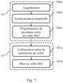
- the smart meter eSM1 150a reprograms the smart meter SM2 150b for a subsequent collection of consumption data measured by said smart meter SM2 150b. More precisely, as detailed in the Fig. 7 , in a step 306a, the smart meter eSM1 150a acknowledges the data transmitted by the smart meter SM2 150b in step 302c. Then, preferably, in a step 306b, the smart meter eSM1 150a temporally synchronizes the smart meter SM2 150b, for example to align the smart meter SM2 150b with the reference of Coordinated Universal Time (UTC). And, in a step 306c, the smart meter eSM1 150a programs a time for the next wake-up (wake-up) of the SM2 150b smart meter.
- UTC Coordinated Universal Time
- the smart meter SM2 150b follows the instructions of the smart meter eSM1 150a and begins a standby period until the next consumption data collection. More precisely, as detailed on the Fig. 7 , in a step 307a, the smart meter SM2 150b configures itself in accordance with the instructions of the smart meter eSM1 150a: time synchronization and programming of the next wake-up time. Then, in a step 307b, the smart meter SM2 150b goes into standby. The batteries of the smart meter SM2 150b are thus preserved.
- the smart meter eSM1 150a When the smart meter eSM1 150a is itself powered by batteries, it is advantageous to take advantage of the waking up of the smart meter eSM1 150a to transmit its own consumption data in addition to the consumption data of the smart meter SM2 150b.
- the smart meter eSM1 150a transmits consumption data to the data concentrator DC 120, this time to the information system IS1 110a. More precisely, as detailed on the Fig. 8 , in a step 308a, the smart meter eSM1 150a obtains consumption data to be transmitted to the information system IS1 110a.
- the smart meter eSM1 150a signs its consumption data using its asymmetric encryption key, and transmits them to the data concentrator DC 120 in a step 308c.
- the transmission between the smart meter eSM1 150a and the data concentrator DC 120 is preferably carried out in a secure manner, using the symmetric encryption key associated with the smart meter eSM1 150a ( ie, the smart meter eSM1 150a encrypts the data with the symmetric encryption key).
- the smart meter eSM1 150a programs its own alarm clock at a wake-up time earlier than the programmed wake-up time of the smart meter SM2 150b and goes into standby in a step 308d.
- the data concentrator DC 120 forwards the consumption data from the smart meter eSM1 150a to the information system IS1 110a (preferably, to the meter data management system MDMS 1 111a).
- the data concentrator DC 120 routes the consumption data received to the information system IS1 110a, since this consumption data relates to a secure link involving the information system IS1 110a.
- the data concentrator DC 120 receives the data transmitted by the smart meter eSM1 150a in step 308c.
- the data concentrator DC 120 uses the symmetric encryption key associated with the smart meter eSM1 150a to decrypt the received data. Then, in a step 309b, the data concentrator DC 120 identifies the recipient of the received data, namely here the information system IS1 110a (preferably, the meter data management system MDMS1 111a). And in a step 309c, the data concentrator DC 120 forwards the consumption data from the smart meter eSM1 150a to the identified recipient.
- the information system IS1 110a preferably, the meter data management system MDMS1 111a
- the information system IS1 110a processes the consumption data from the smart meter eSM1 150a. More specifically, in a step 310a, the information system IS1 110a (preferably, the meter data management system MDMS1 111a) receives the data transmitted by the data concentrator DC 120 in step 309c. Then, in a step 310b, the information system IS1 110a (preferably, the meter data management system MDMS1 111a) verifies the authenticity of the consumption data from the smart meter eSM1 150a using the asymmetric encryption public key associated with the smart meter eSM1 150a. The IS1 110a information system can thus verify that the data received actually come, via the secure link established between the eSM1 150a smart meter and the IS1 110a information system, from consumption measurements carried out by the eSM1 150a smart meter in question.
- a hash function H(.) is used.
- the hash function H(.) is a special function that, from an input data, calculates a digital fingerprint used to quickly identify the initial data.
- the H(.) function is a SHA-2 function (e.g., SHA-224, SHA-256, SHA-384, or SHA-512).
- the resulting HASH fingerprint comprises 256 bits.
- the H(.) function is of type SHA-512
- the resulting HASH fingerprint comprises 512 bits.
- Other functions may be used as the H(.) function, such as, for example, a SHA-3 function, an MD4 function, an MD5 function, a SHA-1 function, all well known in the field of cryptography.
- the aforementioned data set is supplemented with padding bits in order to obtain an alignment on an integer number of bytes suitable for the hash function H(.) to be applied.
- a concatenation of the obtained footprint with the consumption data D is then included in the transmitted data.
- the relevant IS information system can verify that the data received is actually that transmitted by the smart meter in question.
- the IS information system preferably, the relevant MDMS meter data management system 111
- the IS information system After decryption using the asymmetric encryption public key associated with the smart meter in question, the IS information system (preferably, the relevant MDMS meter data management system 111) generates a reference fingerprint with the information it holds concerning the smart meter in question. question. More precisely, the reference fingerprint is generated in the same way as the HASH fingerprint generated by the said smart meter in question, using the consumption data D concatenated with the HASH fingerprint and the serial number of the smart meter known to the information system IS. If the HASH fingerprint and the reference fingerprint coincide, then the data received is indeed data transmitted by the smart meter in question.
Landscapes
- Engineering & Computer Science (AREA)
- Computer Security & Cryptography (AREA)
- Computer Networks & Wireless Communication (AREA)
- Signal Processing (AREA)
- Computer Hardware Design (AREA)
- Computing Systems (AREA)
- General Engineering & Computer Science (AREA)
- Physics & Mathematics (AREA)
- General Physics & Mathematics (AREA)
- Selective Calling Equipment (AREA)
- Arrangements For Transmission Of Measured Signals (AREA)
Applications Claiming Priority (1)
| Application Number | Priority Date | Filing Date | Title |
|---|---|---|---|
| FR2313313A FR3156223A1 (fr) | 2023-11-30 | 2023-11-30 | Procede et systeme de collecte de donnees de consommations mesurees par des compteurs intelligents |
Publications (2)
| Publication Number | Publication Date |
|---|---|
| EP4564744A1 true EP4564744A1 (de) | 2025-06-04 |
| EP4564744B1 EP4564744B1 (de) | 2026-03-11 |
Family
ID=91073030
Family Applications (1)
| Application Number | Title | Priority Date | Filing Date |
|---|---|---|---|
| EP24215605.7A Active EP4564744B1 (de) | 2023-11-30 | 2024-11-26 | Verfahren und system zum sammeln von durch intelligente zähler gemessenen verbrauchsdaten |
Country Status (3)
| Country | Link |
|---|---|
| US (1) | US20250184121A1 (de) |
| EP (1) | EP4564744B1 (de) |
| FR (1) | FR3156223A1 (de) |
Citations (4)
| Publication number | Priority date | Publication date | Assignee | Title |
|---|---|---|---|---|
| EP3122061A1 (de) * | 2015-07-21 | 2017-01-25 | Sagemcom Energy & Telecom Sas | Übertragung von verschlüsselten daten von intelligenten stromzählern aus |
| EP3734984A1 (de) * | 2019-04-30 | 2020-11-04 | Sagemcom Energy & Telecom SAS | Verfahren zum ablesen von fluidzählern |
| EP3759936A1 (de) * | 2018-03-01 | 2021-01-06 | Sagemcom Energy & Telecom SAS | Verfahren zur übertragung mittels eines intelligenten elektrischen zählers, wobei eine nachricht die erkennung eines fehlers in der elektrischen stromversorgung darstellt |
| FR3120968A1 (fr) * | 2021-03-22 | 2022-09-23 | Sagemcom Energy & Telecom Sas | Collecte automatisee d’index de comptage de compteurs de fluide intelligents |
-
2023
- 2023-11-30 FR FR2313313A patent/FR3156223A1/fr active Pending
-
2024
- 2024-11-26 EP EP24215605.7A patent/EP4564744B1/de active Active
- 2024-11-27 US US18/962,777 patent/US20250184121A1/en active Pending
Patent Citations (4)
| Publication number | Priority date | Publication date | Assignee | Title |
|---|---|---|---|---|
| EP3122061A1 (de) * | 2015-07-21 | 2017-01-25 | Sagemcom Energy & Telecom Sas | Übertragung von verschlüsselten daten von intelligenten stromzählern aus |
| EP3759936A1 (de) * | 2018-03-01 | 2021-01-06 | Sagemcom Energy & Telecom SAS | Verfahren zur übertragung mittels eines intelligenten elektrischen zählers, wobei eine nachricht die erkennung eines fehlers in der elektrischen stromversorgung darstellt |
| EP3734984A1 (de) * | 2019-04-30 | 2020-11-04 | Sagemcom Energy & Telecom SAS | Verfahren zum ablesen von fluidzählern |
| FR3120968A1 (fr) * | 2021-03-22 | 2022-09-23 | Sagemcom Energy & Telecom Sas | Collecte automatisee d’index de comptage de compteurs de fluide intelligents |
Non-Patent Citations (1)
| Title |
|---|
| IMTIAZ PARVEZ ET AL: "Key Management and Learning based Two Level Data Security for Metering Infrastructure of Smart Grid", ARXIV.ORG, CORNELL UNIVERSITY LIBRARY, 201 OLIN LIBRARY CORNELL UNIVERSITY ITHACA, NY 14853, 25 September 2017 (2017-09-25), XP080823285 * |
Also Published As
| Publication number | Publication date |
|---|---|
| EP4564744B1 (de) | 2026-03-11 |
| US20250184121A1 (en) | 2025-06-05 |
| FR3156223A1 (fr) | 2025-06-06 |
Similar Documents
| Publication | Publication Date | Title |
|---|---|---|
| US9401895B2 (en) | Device configuration for secure communication | |
| EP3174241B1 (de) | Methode zur herstellung einer gesicherten end-zu-end-kommunikation zwischen dem endgerät eines nutzers und einem verbundenen objekt | |
| EP4064146A1 (de) | Automatisierte erfassung der zählerstände von intelligenten flüssigkeitszählern | |
| EP4564744B1 (de) | Verfahren und system zum sammeln von durch intelligente zähler gemessenen verbrauchsdaten | |
| FR3060886A1 (fr) | Gestion d'energie electrique composite | |
| WO2023232633A1 (fr) | Gestion du rechargement d'un véhicule électrique, borne de rechargement et serveur de gestion de rechargement correspondants. | |
| EP4007290B1 (de) | Verfahren und elektronisches gerät zur steuerung eines kommunikationssystems für einen stromzähler, entsprechendes computerprogramm und entsprechende elektronische datenübertragungsanlage | |
| EP3759936A1 (de) | Verfahren zur übertragung mittels eines intelligenten elektrischen zählers, wobei eine nachricht die erkennung eines fehlers in der elektrischen stromversorgung darstellt | |
| EP4207675B1 (de) | Verfahren zum senden und empfangen von verbrauchsdaten und vorrichtungen zur durchführung des verfahrens | |
| EP4510610B1 (de) | Verfahren und system zur sammlung von verbrauchsdaten, die von intelligenten zählern gemessenen werden | |
| EP4270981B1 (de) | Verfahren zur qualometrischen datengewinnung und system zur durchführung des verfahrens | |
| BE1028512B1 (fr) | Procédé et dispositif électronique de validation d'un appairage d'un système de communication avec un compteur électrique et programme d'ordinateur associé | |
| EP4716232A1 (de) | Kommunikationsverfahren in einem automatisierten intelligenten zählerverwaltungssystem | |
| EP3528464B1 (de) | Verfahren zum koppeln von elektronischen terminals, koppelvorrichtungen, terminals und entsprechendes programm | |
| EP3552136B1 (de) | Verfahren zur verwaltung einer zugangsberechtigung zu einem dienst für eine kommunikationsvorrichtung | |
| EP3321635B1 (de) | Steuerungssystem für die steuerung einer elektrischen anlage, und herstellungsverfahren eines solchen systems | |
| FR3050085A1 (fr) | Procede de chiffrement a clef partagee entre un serveur et un compteur communicant | |
| FR3163478A1 (fr) | Procédé de vérification de données de consommation de ressources, dispositif, système et programme correspondant | |
| FR3025677A1 (fr) | Passerelle pour distribution d'energie en prepaye | |
| KR20070044473A (ko) | 피어-투-피어 네트워크에서의 과금 방법 및 시스템 | |
| EP2930471B1 (de) | Verfahren und anlage zum vergleich des verbrauchs von abwasser ohne verbreitung der gemessenen verbrauchsdaten | |
| EP3953717A1 (de) | Verfahren zur erfassung des energieverbrauchs in einem stromversorgungsdienst | |
| EP4704385A1 (de) | Paarungsverfahren in einem automatisierten intelligenten zählerverwaltungssystem | |
| EP3725025B1 (de) | Sicheres kommunikationsverfahren | |
| FR3127832A1 (fr) | Procede de transmission et de reception de donnees de consommation et dispositifs mettant en œuvre lesdits procedes |
Legal Events
| Date | Code | Title | Description |
|---|---|---|---|
| PUAI | Public reference made under article 153(3) epc to a published international application that has entered the european phase |
Free format text: ORIGINAL CODE: 0009012 |
|
| STAA | Information on the status of an ep patent application or granted ep patent |
Free format text: STATUS: EXAMINATION IS IN PROGRESS |
|
| 17P | Request for examination filed |
Effective date: 20241126 |
|
| AK | Designated contracting states |
Kind code of ref document: A1 Designated state(s): AL AT BE BG CH CY CZ DE DK EE ES FI FR GB GR HR HU IE IS IT LI LT LU LV MC ME MK MT NL NO PL PT RO RS SE SI SK SM TR |
|
| GRAP | Despatch of communication of intention to grant a patent |
Free format text: ORIGINAL CODE: EPIDOSNIGR1 |
|
| STAA | Information on the status of an ep patent application or granted ep patent |
Free format text: STATUS: GRANT OF PATENT IS INTENDED |
|
| RIC1 | Information provided on ipc code assigned before grant |
Ipc: H04L 9/40 20220101AFI20250923BHEP Ipc: H04W 12/033 20210101ALI20250923BHEP Ipc: H04W 12/50 20210101ALI20250923BHEP Ipc: G01D 4/00 20060101ALI20250923BHEP Ipc: H04Q 9/00 20060101ALN20250923BHEP Ipc: H04W 88/04 20090101ALN20250923BHEP |
|
| INTG | Intention to grant announced |
Effective date: 20251009 |
|
| GRAS | Grant fee paid |
Free format text: ORIGINAL CODE: EPIDOSNIGR3 |
|
| GRAA | (expected) grant |
Free format text: ORIGINAL CODE: 0009210 |
|
| STAA | Information on the status of an ep patent application or granted ep patent |
Free format text: STATUS: THE PATENT HAS BEEN GRANTED |
|
| AK | Designated contracting states |
Kind code of ref document: B1 Designated state(s): AL AT BE BG CH CY CZ DE DK EE ES FI FR GB GR HR HU IE IS IT LI LT LU LV MC ME MK MT NL NO PL PT RO RS SE SI SK SM TR |
|
| REG | Reference to a national code |
Ref country code: CH Ref legal event code: F10 Free format text: ST27 STATUS EVENT CODE: U-0-0-F10-F00 (AS PROVIDED BY THE NATIONAL OFFICE) Effective date: 20260311 Ref country code: GB Ref legal event code: FG4D Free format text: NOT ENGLISH |
|
| REG | Reference to a national code |
Ref country code: DE Ref legal event code: R096 Ref document number: 602024003147 Country of ref document: DE |
|
| REG | Reference to a national code |
Ref country code: IE Ref legal event code: FG4D Free format text: LANGUAGE OF EP DOCUMENT: FRENCH |