EP4566730A1 - Dispositif de nettoyage pour nettoyer un composant d'installation, système de nettoyage, agencement et installation de transport - Google Patents
Dispositif de nettoyage pour nettoyer un composant d'installation, système de nettoyage, agencement et installation de transport Download PDFInfo
- Publication number
- EP4566730A1 EP4566730A1 EP24205245.4A EP24205245A EP4566730A1 EP 4566730 A1 EP4566730 A1 EP 4566730A1 EP 24205245 A EP24205245 A EP 24205245A EP 4566730 A1 EP4566730 A1 EP 4566730A1
- Authority
- EP
- European Patent Office
- Prior art keywords
- cleaning
- cleaning device
- system component
- designed
- section
- Prior art date
- Legal status (The legal status is an assumption and is not a legal conclusion. Google has not performed a legal analysis and makes no representation as to the accuracy of the status listed.)
- Pending
Links
Images


Classifications
-
- B—PERFORMING OPERATIONS; TRANSPORTING
- B65—CONVEYING; PACKING; STORING; HANDLING THIN OR FILAMENTARY MATERIAL
- B65G—TRANSPORT OR STORAGE DEVICES, e.g. CONVEYORS FOR LOADING OR TIPPING, SHOP CONVEYOR SYSTEMS OR PNEUMATIC TUBE CONVEYORS
- B65G45/00—Lubricating, cleaning, or clearing devices
- B65G45/10—Cleaning devices
-
- B—PERFORMING OPERATIONS; TRANSPORTING
- B65—CONVEYING; PACKING; STORING; HANDLING THIN OR FILAMENTARY MATERIAL
- B65G—TRANSPORT OR STORAGE DEVICES, e.g. CONVEYORS FOR LOADING OR TIPPING, SHOP CONVEYOR SYSTEMS OR PNEUMATIC TUBE CONVEYORS
- B65G45/00—Lubricating, cleaning, or clearing devices
- B65G45/10—Cleaning devices
- B65G45/26—Cleaning devices for gathering residue after cleaning
-
- B—PERFORMING OPERATIONS; TRANSPORTING
- B08—CLEANING
- B08B—CLEANING IN GENERAL; PREVENTION OF FOULING IN GENERAL
- B08B1/00—Cleaning by methods involving the use of tools
-
- A—HUMAN NECESSITIES
- A47—FURNITURE; DOMESTIC ARTICLES OR APPLIANCES; COFFEE MILLS; SPICE MILLS; SUCTION CLEANERS IN GENERAL
- A47L—DOMESTIC WASHING OR CLEANING; SUCTION CLEANERS IN GENERAL
- A47L9/00—Details or accessories of suction cleaners, e.g. mechanical means for controlling the suction or for effecting pulsating action; Storing devices specially adapted to suction cleaners or parts thereof; Carrying-vehicles specially adapted for suction cleaners
- A47L9/0009—Storing devices ; Supports, stands or holders
- A47L9/0063—External storing devices; Stands, casings or the like for the storage of suction cleaners
-
- A—HUMAN NECESSITIES
- A47—FURNITURE; DOMESTIC ARTICLES OR APPLIANCES; COFFEE MILLS; SPICE MILLS; SUCTION CLEANERS IN GENERAL
- A47L—DOMESTIC WASHING OR CLEANING; SUCTION CLEANERS IN GENERAL
- A47L9/00—Details or accessories of suction cleaners, e.g. mechanical means for controlling the suction or for effecting pulsating action; Storing devices specially adapted to suction cleaners or parts thereof; Carrying-vehicles specially adapted for suction cleaners
- A47L9/009—Carrying-vehicles; Arrangements of trollies or wheels; Means for avoiding mechanical obstacles
-
- A—HUMAN NECESSITIES
- A47—FURNITURE; DOMESTIC ARTICLES OR APPLIANCES; COFFEE MILLS; SPICE MILLS; SUCTION CLEANERS IN GENERAL
- A47L—DOMESTIC WASHING OR CLEANING; SUCTION CLEANERS IN GENERAL
- A47L9/00—Details or accessories of suction cleaners, e.g. mechanical means for controlling the suction or for effecting pulsating action; Storing devices specially adapted to suction cleaners or parts thereof; Carrying-vehicles specially adapted for suction cleaners
- A47L9/28—Installation of the electric equipment, e.g. adaptation or attachment to the suction cleaner; Controlling suction cleaners by electric means
- A47L9/2805—Parameters or conditions being sensed
-
- A—HUMAN NECESSITIES
- A47—FURNITURE; DOMESTIC ARTICLES OR APPLIANCES; COFFEE MILLS; SPICE MILLS; SUCTION CLEANERS IN GENERAL
- A47L—DOMESTIC WASHING OR CLEANING; SUCTION CLEANERS IN GENERAL
- A47L9/00—Details or accessories of suction cleaners, e.g. mechanical means for controlling the suction or for effecting pulsating action; Storing devices specially adapted to suction cleaners or parts thereof; Carrying-vehicles specially adapted for suction cleaners
- A47L9/28—Installation of the electric equipment, e.g. adaptation or attachment to the suction cleaner; Controlling suction cleaners by electric means
- A47L9/2894—Details related to signal transmission in suction cleaners
-
- B—PERFORMING OPERATIONS; TRANSPORTING
- B08—CLEANING
- B08B—CLEANING IN GENERAL; PREVENTION OF FOULING IN GENERAL
- B08B1/00—Cleaning by methods involving the use of tools
- B08B1/10—Cleaning by methods involving the use of tools characterised by the type of cleaning tool
- B08B1/12—Brushes
-
- B—PERFORMING OPERATIONS; TRANSPORTING
- B08—CLEANING
- B08B—CLEANING IN GENERAL; PREVENTION OF FOULING IN GENERAL
- B08B1/00—Cleaning by methods involving the use of tools
- B08B1/20—Cleaning of moving articles, e.g. of moving webs or of objects on a conveyor
-
- B—PERFORMING OPERATIONS; TRANSPORTING
- B08—CLEANING
- B08B—CLEANING IN GENERAL; PREVENTION OF FOULING IN GENERAL
- B08B1/00—Cleaning by methods involving the use of tools
- B08B1/30—Cleaning by methods involving the use of tools by movement of cleaning members over a surface
- B08B1/32—Cleaning by methods involving the use of tools by movement of cleaning members over a surface using rotary cleaning members
- B08B1/34—Cleaning by methods involving the use of tools by movement of cleaning members over a surface using rotary cleaning members rotating about an axis parallel to the surface
-
- B—PERFORMING OPERATIONS; TRANSPORTING
- B08—CLEANING
- B08B—CLEANING IN GENERAL; PREVENTION OF FOULING IN GENERAL
- B08B13/00—Accessories or details of general applicability for machines or apparatus for cleaning
-
- B—PERFORMING OPERATIONS; TRANSPORTING
- B08—CLEANING
- B08B—CLEANING IN GENERAL; PREVENTION OF FOULING IN GENERAL
- B08B3/00—Cleaning by methods involving the use or presence of liquid or steam
- B08B3/02—Cleaning by the force of jets or sprays
-
- B—PERFORMING OPERATIONS; TRANSPORTING
- B08—CLEANING
- B08B—CLEANING IN GENERAL; PREVENTION OF FOULING IN GENERAL
- B08B3/00—Cleaning by methods involving the use or presence of liquid or steam
- B08B3/02—Cleaning by the force of jets or sprays
- B08B3/024—Cleaning by means of spray elements moving over the surface to be cleaned
-
- B—PERFORMING OPERATIONS; TRANSPORTING
- B08—CLEANING
- B08B—CLEANING IN GENERAL; PREVENTION OF FOULING IN GENERAL
- B08B5/00—Cleaning by methods involving the use of air flow or gas flow
-
- B—PERFORMING OPERATIONS; TRANSPORTING
- B08—CLEANING
- B08B—CLEANING IN GENERAL; PREVENTION OF FOULING IN GENERAL
- B08B5/00—Cleaning by methods involving the use of air flow or gas flow
- B08B5/02—Cleaning by the force of jets, e.g. blowing-out cavities
-
- B—PERFORMING OPERATIONS; TRANSPORTING
- B08—CLEANING
- B08B—CLEANING IN GENERAL; PREVENTION OF FOULING IN GENERAL
- B08B5/00—Cleaning by methods involving the use of air flow or gas flow
- B08B5/04—Cleaning by suction, with or without auxiliary action
-
- B—PERFORMING OPERATIONS; TRANSPORTING
- B08—CLEANING
- B08B—CLEANING IN GENERAL; PREVENTION OF FOULING IN GENERAL
- B08B5/00—Cleaning by methods involving the use of air flow or gas flow
- B08B5/04—Cleaning by suction, with or without auxiliary action
- B08B5/043—Cleaning travelling work
- B08B5/046—Cleaning moving webs
-
- B—PERFORMING OPERATIONS; TRANSPORTING
- B08—CLEANING
- B08B—CLEANING IN GENERAL; PREVENTION OF FOULING IN GENERAL
- B08B9/00—Cleaning hollow articles by methods or apparatus specially adapted thereto
- B08B9/08—Cleaning containers, e.g. tanks
- B08B9/0804—Cleaning containers having tubular shape, e.g. casks, barrels, drums
- B08B9/0808—Cleaning containers having tubular shape, e.g. casks, barrels, drums by methods involving the use of tools, e.g. by brushes, scrapers
-
- B—PERFORMING OPERATIONS; TRANSPORTING
- B08—CLEANING
- B08B—CLEANING IN GENERAL; PREVENTION OF FOULING IN GENERAL
- B08B9/00—Cleaning hollow articles by methods or apparatus specially adapted thereto
- B08B9/08—Cleaning containers, e.g. tanks
- B08B9/0804—Cleaning containers having tubular shape, e.g. casks, barrels, drums
- B08B9/0813—Cleaning containers having tubular shape, e.g. casks, barrels, drums by the force of jets or sprays
-
- B—PERFORMING OPERATIONS; TRANSPORTING
- B08—CLEANING
- B08B—CLEANING IN GENERAL; PREVENTION OF FOULING IN GENERAL
- B08B9/00—Cleaning hollow articles by methods or apparatus specially adapted thereto
- B08B9/08—Cleaning containers, e.g. tanks
- B08B9/087—Cleaning containers, e.g. tanks by methods involving the use of tools, e.g. brushes, scrapers
-
- B—PERFORMING OPERATIONS; TRANSPORTING
- B08—CLEANING
- B08B—CLEANING IN GENERAL; PREVENTION OF FOULING IN GENERAL
- B08B9/00—Cleaning hollow articles by methods or apparatus specially adapted thereto
- B08B9/08—Cleaning containers, e.g. tanks
- B08B9/093—Cleaning containers, e.g. tanks by the force of jets or sprays
-
- B—PERFORMING OPERATIONS; TRANSPORTING
- B65—CONVEYING; PACKING; STORING; HANDLING THIN OR FILAMENTARY MATERIAL
- B65G—TRANSPORT OR STORAGE DEVICES, e.g. CONVEYORS FOR LOADING OR TIPPING, SHOP CONVEYOR SYSTEMS OR PNEUMATIC TUBE CONVEYORS
- B65G29/00—Rotary conveyors, e.g. rotating discs, arms, star-wheels or cones
- B65G29/02—Rotary conveyors, e.g. rotating discs, arms, star-wheels or cones for inclined or vertical transit
-
- B—PERFORMING OPERATIONS; TRANSPORTING
- B65—CONVEYING; PACKING; STORING; HANDLING THIN OR FILAMENTARY MATERIAL
- B65G—TRANSPORT OR STORAGE DEVICES, e.g. CONVEYORS FOR LOADING OR TIPPING, SHOP CONVEYOR SYSTEMS OR PNEUMATIC TUBE CONVEYORS
- B65G35/00—Mechanical conveyors not otherwise provided for
-
- B—PERFORMING OPERATIONS; TRANSPORTING
- B65—CONVEYING; PACKING; STORING; HANDLING THIN OR FILAMENTARY MATERIAL
- B65G—TRANSPORT OR STORAGE DEVICES, e.g. CONVEYORS FOR LOADING OR TIPPING, SHOP CONVEYOR SYSTEMS OR PNEUMATIC TUBE CONVEYORS
- B65G45/00—Lubricating, cleaning, or clearing devices
- B65G45/10—Cleaning devices
- B65G45/22—Cleaning devices comprising fluid applying means
-
- A—HUMAN NECESSITIES
- A47—FURNITURE; DOMESTIC ARTICLES OR APPLIANCES; COFFEE MILLS; SPICE MILLS; SUCTION CLEANERS IN GENERAL
- A47L—DOMESTIC WASHING OR CLEANING; SUCTION CLEANERS IN GENERAL
- A47L2201/00—Robotic cleaning machines, i.e. with automatic control of the travelling movement or the cleaning operation
- A47L2201/02—Docking stations; Docking operations
- A47L2201/024—Emptying dust or waste liquid containers
-
- B—PERFORMING OPERATIONS; TRANSPORTING
- B08—CLEANING
- B08B—CLEANING IN GENERAL; PREVENTION OF FOULING IN GENERAL
- B08B2203/00—Details of cleaning machines or methods involving the use or presence of liquid or steam
- B08B2203/02—Details of machines or methods for cleaning by the force of jets or sprays
- B08B2203/0229—Suction chambers for aspirating the sprayed liquid
-
- B—PERFORMING OPERATIONS; TRANSPORTING
- B65—CONVEYING; PACKING; STORING; HANDLING THIN OR FILAMENTARY MATERIAL
- B65G—TRANSPORT OR STORAGE DEVICES, e.g. CONVEYORS FOR LOADING OR TIPPING, SHOP CONVEYOR SYSTEMS OR PNEUMATIC TUBE CONVEYORS
- B65G53/00—Conveying materials in bulk through troughs, pipes or tubes by floating the materials or by flow of gas, liquid or foam
- B65G53/34—Details
- B65G53/40—Feeding or discharging devices
- B65G53/46—Gates or sluices, e.g. rotary wheels
- B65G53/4608—Turnable elements, e.g. rotary wheels with pockets or passages for material
- B65G53/4625—Turnable elements, e.g. rotary wheels with pockets or passages for material with axis of turning perpendicular to flow
- B65G53/4633—Turnable elements, e.g. rotary wheels with pockets or passages for material with axis of turning perpendicular to flow the element having pockets, rotated from charging position to discharging position, i.e. discrete flow
-
- B—PERFORMING OPERATIONS; TRANSPORTING
- B65—CONVEYING; PACKING; STORING; HANDLING THIN OR FILAMENTARY MATERIAL
- B65G—TRANSPORT OR STORAGE DEVICES, e.g. CONVEYORS FOR LOADING OR TIPPING, SHOP CONVEYOR SYSTEMS OR PNEUMATIC TUBE CONVEYORS
- B65G65/00—Loading or unloading
- B65G65/30—Methods or devices for filling or emptying bunkers, hoppers, tanks, or like containers, of interest apart from their use in particular chemical or physical processes or their application in particular machines, e.g. not covered by a single other subclass
- B65G65/34—Emptying devices
- B65G65/40—Devices for emptying otherwise than from the top
- B65G65/48—Devices for emptying otherwise than from the top using other rotating means, e.g. rotating pressure sluices in pneumatic systems
Definitions
- the invention relates to a cleaning device for cleaning a system component, for example, a rotary valve. Furthermore, the invention relates to a cleaning system, an arrangement, and a conveyor system with such a cleaning device.
- the invention is based on the object of structurally and/or functionally improving a cleaning device mentioned above. Furthermore, the invention is based on the object of structurally and/or functionally improving a cleaning system, an arrangement, and a conveyor system.
- the object is achieved by a cleaning device having the features of claim 1. Furthermore, the object is achieved by a cleaning system having the features of claim 13. Furthermore, the object is achieved by an arrangement with the features of claim 14 or with a conveyor system with the features of claim 1 7.
- the essence of the invention is in particular that the cleaning device can automatically initiate a cleaning process for cleaning the system component and, in particular, can carry out the cleaning automatically.
- a cleaning device which is designed to clean a system component of a conveyor system.
- the cleaning device can also be referred to as a cleaning satellite and/or designed as a cleaning robot.
- the conveyor system is designed here to convey bulk material.
- the conveyor system can be configured as a pneumatic conveyor system.
- the bulk material can be granules, granular material, particles, powder, or flakes.
- the bulk material can be a plastic material, a foodstuff, such as milk powder or milk substitute powder, an animal feed, a pharmaceutical substance or drug, a drug, or a battery material, such as a coating mixture or an anode or cathode material.
- the cleaning device comprises at least one cleaning tool.
- the cleaning device and/or its cleaning tool can be configured for dry, moist, and/or wet cleaning.
- the at least one cleaning tool can be, for example, a blowing device, spraying device, brushing device, blade device, and/or wiping device.
- a suction device is also possible as cleaning tool.
- the cleaning tool can additionally have a suction device.
- the cleaning tool can, for example, have at least one spray head, at least one spray nozzle, at least one air nozzle, at least one brush, at least one blade/scraper, and/or at least one wiper.
- these cleaning elements can also be designed to be rotatable or pivotable.
- the blowing device can comprise the at least one air nozzle.
- the blowing device can be designed to blow out dry or moist air.
- the blowing device can be designed to provide and/or blow out tempered air, for example, cold, warm, or hot.
- the blowing device can be connected to an air source, for example, a compressed air source.
- the blowing device can thus also blow out compressed air.
- the cleaning tool can, for example, have at least one wet wiper or at least one wet brush.
- the cleaning tool can have at least one spray ball, spray lance, jet cleaner, or orbital cleaner. The cleaning tool can thus be designed to spray the system component or a part thereof, for example, with a cleaning agent.
- the cleaning tool can comprise a laser device, an ultrasonic device, or a blasting device, for example, a sandblasting device or a glass bead blasting device.
- the at least one cleaning tool is thus capable of cleaning the system component or at least a portion of the system component and thus removing dirt and/or deposits.
- the cleaning device has a support section which is designed to fasten the cleaning device to the system component, to a transport device and/or to a third object.
- the cleaning device can therefore be designed as a stationary cleaning device, for example attached to the system component or to the third object.
- the third object can be, for example, a part or section of the conveyor system or a part of the building in which the conveyor system is installed, such as a wall, ceiling or floor of the building.
- the connection of the cleaning device to the system component or the third object can be designed as a flange connection, screw connection and/or clamping connection or the support section can have such a connection.
- the support section can further have a hinge, an arm, such as a robot arm or telescopic arm, a cylinder and/or a guide, such as a linear guide.
- the support section can comprise a docking element for docking to the system component, to the transport device and/or to the third object.
- the cleaning device can be designed as a mobile cleaning device, for example by means of the transport device, by means of which the cleaning device is automatically movable or can move in the application space. In this case, the cleaning device can be connected to the transport device by means of the support section.
- the cleaning device is particularly designed to automatically initiate and/or carry out a cleaning process for cleaning at least part of the system component.
- the cleaning device is thus able to automatically carry out the cleaning of the system component, in particular by means of the at least one cleaning tool.
- Automatically can also be understood to mean that the cleaning device can automatically initiate a cleaning process and/or automatically carry out cleaning of the system component or at least part thereof.
- the cleaning device can also be configured to receive an external command to start a cleaning process and/or to start a cleaning process automatically, for example after a defined time interval has elapsed and/or based on an assessment of whether cleaning is necessary or not.
- the cleaning device can thus be designed for self-sufficient cleaning.
- the cleaning device enables automatic and/or self-cleaning of the system components.
- the cleaning device enables automated, for example autonomous or semi-autonomous, cleaning of the system components.
- the cleaning device therefore creates the prerequisite for partially or fully automated cleaning of the System components. In particular, this allows for better compliance with hygiene requirements and enables safe and efficient cleaning, especially without human interaction. Health risks associated with cleaning system components caused by harmful, particularly toxic, substances, for example, through the use of toxic or irritating cleaning agents or in the areas of pharmaceutical product manufacturing and/or battery production, are also reduced or completely avoided.
- the cleaning device can have a communication interface.
- the communication interface can be configured to communicate with the system component and/or with a control device of the conveyor system.
- the communication interface can be designed to receive and/or transmit signals and/or data.
- the communication interface can be configured to receive a cleaning signal.
- the cleaning device can have a control device, for example with a processor and/or memory.
- the cleaning device can be designed to initiate and/or carry out the cleaning process after a cleaning signal has been received via the communication interface.
- the system component is preferably or comprises a conveying device, a feeding element, a supply device, a dosing device, a lock, a rotating part, a switch, a slide valve, a flap or a conveyor screw.
- the lock can be, for example, a rotary valve, a blow-through valve or a discharge valve.
- the slide valve can be designed as a gate valve.
- the system component can be designed for feeding or discharging bulk material into or from a conveying line of the conveying system.
- the system component can be or comprise a mixing device or a separating device.
- the separating device can be a device for classifying solids according to defined criteria, for example a classifier.
- the system component can be designed as a rotary valve.
- the rotary valve can have an interior Housing and a pull-out side cover detachably attached to the housing. Furthermore, the rotary valve can have a rotary valve.
- the rotary valve can be arranged in an operating position in the housing so as to be rotatably driven about a longitudinal axis and can be held on the pull-out side cover.
- the rotary valve has a pull-out device for displacing the rotary valve between the operating position and a pull-out position.
- the pull-out device can have a guide unit for the guided displacement of the rotary valve along a pull-out direction parallel to the longitudinal axis.
- the pull-out device can comprise a pull-out drive, in particular a motor-driven drive, which is fixed to the housing and coupled to the pull-out side cover for the mechanically driven displacement of the pull-out side cover with the rotary valve.
- the rotary valve can therefore be displaced between an operating position and a pull-out position in a driven and guided manner by means of the pull-out device. This allows the cell wheel to be moved partially or fully automatically into the pull-out position for a cleaning process.
- the cleaning device can have a detection sensor system.
- the detection sensor system can be configured, in particular, to detect a state of the system component, for example, whether the system component is in an open or closed state. Additionally or alternatively, the detection sensor system can be configured to detect whether the system component is in an extended or retracted state.
- the cleaning device can be designed to initiate and/or carry out a cleaning process based on the detected state.
- the detection sensor system can be configured to detect an open or closed state of the rotary valve and/or an extended or retracted state of the rotary valve, i.e., a state as to whether the rotary valve is in the operating position or the extended position.
- the cleaning device can be designed to initiate and/or carry out a cleaning process if it has been detected that the rotary valve is in the open or extended state or that the rotary valve is in the extended position.
- the cleaning device can comprise a cleaning section designed to define a cleaning chamber with the system component or a part thereof.
- the cleaning section can be designed to correspond to or complement the system component or a part thereof.
- the cleaning section can be designed as a cover part, such as a side cover.
- the cleaning section can thus be designed as the side cover of a rotary valve.
- the cleaning section can be designed as a cleaning side cover that can be pressed or pushed onto the housing of the system component.
- the at least one cleaning tool can be arranged on the cleaning section.
- At least one drive for the cleaning tool and/or at least one drive for an active element of the system component can be provided on the cleaning section, for example on a side of the cleaning section facing away from the cleaning tool or the active element.
- a drive module can be provided.
- the drive module can have at least one drive for the cleaning tool and/or at least one drive for the active element of the system component.
- the at least one drive can be designed to drive the active element of the system component, for example, to rotate it.
- at least one line for supplying an auxiliary substance, such as energy, electricity, air, water, blasting agent, cleaning agent, or the like, and/or at least one line for removing a contaminant can be provided at the cleaning section, for example, on a side of the cleaning section facing away from the cleaning tool.
- the cleaning section can be designed to be movable by means of a movement device, for example, by means of at least one linear guide, a rotating device, or an arm, such as an articulated, pivoting, and/or guide arm.
- the cleaning tool can therefore be inserted into the interior of the housing of the system component by means of the cleaning device or its movement device, with the system component open.
- the cleaning tool can therefore be designed to be insertable into the housing of the system component.
- the cleaning section can close the system component, in particular such that the interior of the housing forms the cleaning space.
- the cleaning section can thus be designed to define a closed cleaning space with the system component or a part thereof. This allows the interior of the housing of the system component to be easily cleaned using the cleaning device or its cleaning tool.
- the cleaning section can be designed to enclose the system component or a part thereof in a cleaning chamber.
- the cleaning section can be designed as a housing, for example as a cylinder housing or drum, e.g., a washing drum.
- the housing can also be referred to as a cleaning housing.
- the housing can be open on one side, for example as a hollow cylinder open on one side.
- the housing can also be designed in several parts, e.g., in two parts. In this case, two half-shells can form the housing, which can be designed to be movable relative to one another.
- the housing can delimit or define an interior space, such as a cleaning chamber.
- the cleaning section can thus form an enclosure for at least some of the system components, e.g., for the cellular wheel.
- the at least one cleaning tool can be arranged in the housing or in its interior space.
- at least one drive for the cleaning tool and/or at least one drive for an active element of the system component can be provided on the housing.
- a drive module can be provided.
- the drive module can have at least one drive for the cleaning tool and/or at least one drive for the active element of the system component.
- the at least one drive can be designed to drive the active element of the system component, for example to rotate it.
- At least one line for supplying an auxiliary substance, such as energy, electricity, air, water, blasting agent, cleaning agent or the like, and/or at least one line for discharging a contaminant can be provided on the housing.
- the cleaning section can be designed to be movable by means of a movement device, for example by means of at least one linear guide, a rotating device or an arm, such as an articulated, pivoting and/or guide arm.
- the cleaning section or the housing can therefore, when the system component is open, form part of the
- the cleaning section can enclose or be placed over a system component, such as the cellular wheel.
- the cleaning section can enclose the system component or a part thereof, for example in such a way that the interior of the cleaning section forms the cleaning chamber with the part of the system component.
- the cleaning section can thus be designed to delimit a closed cleaning chamber with the system component or a part thereof. As a result, at least a part of the system component, such as a cellular wheel, can be easily cleaned using the cleaning device or its cleaning tool.
- the cleaning section can comprise a connecting section.
- the connecting section can be designed, for example, as a flange part.
- the connecting section can be arranged on the cover part of the cleaning section or formed by it.
- the connecting section can be arranged on the housing of the cleaning section or formed by it, for example on or through the open housing side.
- the connecting section can have a sealing device which is designed to sealingly connect the cleaning section to the system component or to a part thereof.
- the cleaning device can have at least one suction device for extracting dirt.
- the suction device can be configured for dry and/or wet suction.
- the suction device can have at least one suction line, which is arranged, for example, at the cleaning section and/or extends or opens into the cleaning chamber.
- a suction pump can be provided, which is operatively connected, in particular, to the at least one suction line.
- the cleaning device may have at least one storage container.
- the cleaning device may have a storage container for contaminants and at least one storage container for an auxiliary material.
- An auxiliary material may, for example, be energy, e.g. electrical energy or current, air, e.g. purge air, compressed air, hot air or cooling air, water, e.g. fresh water, purge water, hot water or cooling water, a blasting medium, e.g. sand or glass, or a cleaning agent, e.g. solvent, rinsing agent or foam concentrate.
- a contaminant can, for example, be dirt in dry, wet or liquid form, e.g. as particles, powder, dust or dirty water.
- the at least one storage container can therefore be a tank for storing an auxiliary substance or a storage device, e.g. an energy storage device such as a rechargeable battery or a battery.
- the cleaning device can have at least one transmission interface for transmitting an auxiliary substance or contaminant.
- the transmission interface can have at least one transmission line.
- the at least one transmission interface or its at least one transmission line can be designed such that it can be connectable to a service station.
- the service station can be a separately provided service station or a service station arranged on and/or assigned to the system component.
- the contaminant and/or the at least one auxiliary agent can be transferred from the cleaning device to a service station. This allows the storage containers to be emptied, but also, if provided, filled and/or recharged.
- the transfer interface can also be connected to an interface provided on the system component or conveyor system for removing contaminants and/or supplying auxiliary agents.
- the support section can have a movement device.
- the movement device can have at least one linear guide, for example two or three linear guides.
- the linear guides can be arranged substantially perpendicular to one another, for example so that linear guidance can take place along two or three mutually perpendicular axes.
- the movement device can have a pivoting mechanism, e.g. a rotation device, with which pivoting or rotation about an axis, for example about a vertical axis, vertical axis or transverse axis, can be carried out.
- an arm such as an articulated, pivoting and/or guide arm, can be provided.
- the arm can also be designed as a robot arm, for example, with one, two, three, or more axes.
- the support section can be designed as a hinge or at least have a hinge element.
- the movement device can move the cleaning device relative to the system component.
- the cleaning section can be connected to the movement device so that the cleaning section can be moved relative to the system component.
- the cleaning device can comprise the transport device.
- the cleaning device can be attached or mounted to the transport device by means of the carrier section.
- the transport device can be designed, in particular, for transporting the cleaning device.
- the transport device can be designed as an autonomous or semi-autonomous, self-propelled vehicle or self-flying aircraft. This can be, for example, a motor-driven vehicle or a flight-capable drone.
- the vehicle or aircraft can comprise at least one storage container for storing an auxiliary material and/or contaminant.
- the vehicle or aircraft can comprise at least one storage device, for example, an energy storage device such as a rechargeable battery or a battery.
- the vehicle or aircraft can comprise at least one cleaning tool, for example, the spraying device.
- the cleaning device can therefore also be designed as a cleaning vehicle or a cleaning drone.
- the transport device can comprise at least one drive, for example, a motor, such as an electric motor and/or rotor.
- the transport device can comprise wings, rotatably driven wheels, and/or rotor blades.
- the transport system can be configured for autonomous or semi-autonomous operation. Additionally or alternatively, the transport system can be configured for remote control and/or manual operation. Autonomous or semi-autonomous operation, or alternatively, remote control, is particularly advantageous when hazardous substances, such as those used in pharmaceutical products or battery production, are processed or transported by the conveyor system.
- the transport device can also comprise a control device configured to control the transport device.
- a control device configured to control the transport device.
- an environmental sensor system can be provided, which is configured to provide the control device with environmental data representing the environment of the cleaning device.
- a navigation device can be provided, which is configured to determine the current position of the cleaning device.
- the control device can be connected, in particular wirelessly or by radio, to a central control device and/or to the control device of the conveyor system.
- the control device can be configured to receive and/or transmit data, information, or signals.
- the cleaning device can therefore be capable of moving automatically and/or independently by means of the transport device, in particular within a space or area of application. This makes it possible for the cleaning device to clean multiple and/or difficult-to-access components of the conveyor system.
- the cleaning device can be designed such that independent orientation can be carried out at least within the space or area of application, for example by processing a position detected by the environmental sensors and/or provided by the navigation device.
- the navigation device can comprise stored map data, for example for determining and/or comparing a position, and/or access this data via an interface.
- the navigation device can be or have a GPS navigation device, for example.
- the space or area of application can be the area or space determined and/or limited by the conveyor system or, alternatively, only a sub-area thereof.
- a cleaning system for cleaning a system component of a conveyor system.
- the conveyor system serves to convey bulk material.
- the system component and/or conveyor system can be designed as described above and/or below.
- the cleaning system comprises, in particular, at least one cleaning device, which can be designed as described above and/or below.
- the cleaning system can have at least one service station.
- the cleaning device is configured such that it can move to the service station independently and/or automatically, for example by means of the transport device.
- the cleaning device is able to detect whether a trip to a service station is necessary or not.
- a trip to the service station may be necessary, for example, when a storage container, e.g. an auxiliary material tank and/or dirt tank, of the cleaning device is essentially empty or full. This may also include the need to charge a battery of the cleaning device.
- the cleaning device can remove the at least one auxiliary substance and/or energy for charging a battery from the service station. Furthermore, the cleaning device can transfer the at least one contaminant to the service station.
- the service station can be configured to transfer at least one auxiliary substance and/or contaminant to or from the at least one cleaning device.
- the service station can have at least one service nozzle for connection to the at least one cleaning device.
- the cleaning device can then comprise at least one connecting nozzle. The transfer of an auxiliary substance or the removal of contaminant can take place as required.
- the service station can have at least one tank.
- the service station can have at least one charging device configured to charge a battery and/or rechargeable battery of the at least one cleaning device.
- the cleaning device can return to the location of the cleaning task, move to a new cleaning task or be in a standby mode for a future cleaning task.
- an arrangement which comprises at least one cleaning device and at least one system component.
- the at least one cleaning device can be as described above and/or below described.
- the cleaning device can be attached to the system component by means of the support section.
- the cleaning device can be attached to the third object.
- the at least one system component can be designed as described above and/or below.
- the system component can be or comprise a conveyor device, a feed element, a feeding device, a dosing device, a lock, a rotating part, a switch, a slide valve, a flap or a conveyor screw.
- the lock can be, for example, a rotary valve, a blow-through valve or a discharge valve.
- the rotary valve can be designed as described above and/or below.
- the slide valve can be designed as a gate valve.
- the system component can be designed for feeding or discharging bulk material into or from a conveyor line of the conveyor system.
- the system component can be or comprise a mixing device or a separating device.
- the separating device can be a device for classifying solids according to defined criteria, for example a classifier.
- the at least one system component is designed for manual or automatic opening.
- the system component can have a pull-out device for displacing an active element of the system component between an operating position and a pull-out position.
- the active element can thus be designed to be movable out of a housing of the system component.
- the active element can be, for example, a rotating part, a cellular wheel, a slide, a flap, or a screw conveyor.
- the pull-out device can have a guide unit for the guided displacement of the active element along a pull-out direction parallel to the longitudinal axis.
- the pull-out device can comprise a pull-out drive, for example a motor-driven one, for the mechanically driven displacement of the active element.
- the active element can therefore be driven and guided between an operating position and a pull-out position by means of the pull-out device. This allows a partially or fully automated displacement of the active element into the pull-out position for a cleaning process.
- a conveyor system for conveying bulk material comprises at least one arrangement configured as described above and/or below. Additionally or alternatively, the conveyor system may have a cleaning system. The cleaning system may be configured as described above and/or below.
- Fig. 1 schematically shows a cleaning system 100 for cleaning a system component 102 of a conveyor system 104.
- the conveyor system 104 is designed to convey bulk material 106 and comprises at least one conveyor line 108, into which the system component 102 is integrated.
- the system component 102 is designed as a rotary valve 102.
- the rotary valve 102 has a housing 110 having an interior space and a rotary valve 112 rotatably mounted in the housing 110.
- the rotary valve 102 comprises a pull-out side cover (in Fig. 1 not shown).
- the cellular wheel 112 is arranged in an operating position in the housing 110 so as to be rotatably driven about a longitudinal axis and is held on the extraction side cover.
- the cellular wheel lock 102 has an extraction device (in Fig. 1 not shown) for displacing the cellular wheel 112 between the operating position and a pull-out position.
- the pull-out device can have a guide unit for the guided displacement of the cellular wheel 112 along a pull-out direction parallel to the longitudinal axis.
- the pull-out device can have a housing-fixed and coupled to the pull-out side cover, in particular A motorized pull-out drive for the mechanically driven movement of the pull-out side cover with the cellular wheel 112 can thus be moved between the operating position and the pull-out position by means of the pull-out device. Since the cellular wheel lock 102 is designed for automatic opening, a partially or fully automated movement of the cellular wheel 112 into the pull-out position or cleaning position can take place, particularly for a cleaning process.
- the cleaning system 100 now comprises at least one cleaning device 114 for cleaning the rotary valve 102 and at least one service station 116 for transferring at least one auxiliary substance and/or contaminant to or from the at least one cleaning device 114.
- An auxiliary substance can be, for example, energy, electricity, air, water, blasting agent, cleaning agent, or the like.
- the cleaning device 114 is designed to receive at least one auxiliary substance from a tank or reservoir of the service station 116.
- the cleaning device 114 can connect to the service station 116, e.g., via a transmission interface, such as a line or a nozzle, such that at least one storage container or reservoir of the cleaning device 114 can be filled or loaded with the respective auxiliary substance.
- the storage containers serve to store the auxiliary substances. Similarly, contaminant stored in a tank of the cleaning device 114, which has been generated by a cleaning process and picked up by the cleaning device 114, can be delivered to the service station 116 in order to empty the contaminant tank of the cleaning device 114.
- the cleaning device 114 is in Fig. 1 schematically shown and comprises at least one cleaning tool 118 for cleaning at least a portion of the rotary valve 102.
- the cleaning device 114 is designed to initiate and/or carry out a cleaning process for cleaning at least a portion of the rotary valve 102 independently and/or automatically.
- the cleaning tool 118 can be configured for dry, moist, and/or wet cleaning.
- the cleaning tool can be a spray device
- the cleaning device 114 can be a blowing device, a brushing device, a blade device, and/or a wiping device.
- the cleaning device 114 has at least one suction device 120 for sucking away the dirt after or during the cleaning process.
- the cleaning device 114 has a transport device 122 and a support section 124.
- the cleaning device 114 is fastened to the transport device 122 by means of the support section 124.
- the support section 124 can be designed to fasten the cleaning device 114 to the rotary valve 102 and/or to a third object, for example the conveyor system 104, its conveyor line 108, or to a wall, ceiling, or floor of the building in which the conveyor system is installed.
- the support section 124 preferably comprises a movement device designed to move the cleaning device 114 relative to the rotary valve 102. This allows optimal positioning of the cleaning tool 118 relative to the rotary valve.
- the transport device 122 is designed to transport the cleaning device 114.
- the transport device 122 is configured as an autonomous or semi-autonomous, self-propelled vehicle.
- the transport device 122 has a drive, for example an electric motor, and at least three wheels.
- the transport device 122 thus enables autonomous or semi-autonomous driving operation of the cleaning device 114.
- a remote control operation and/or a manual operating mode can be provided.
- the transport device 122 comprises an environmental sensor system.
- the environmental sensor system can, for example, have a plurality of radar sensors, lidar sensors, or the like.
- the environmental sensor system is configured to provide a control device with the environmental data representing an environment of the cleaning device 114.
- a navigation device can be provided which is configured to determine the current position of the cleaning device 114 in the application space or application area. to enable navigation, for example, from the service station 116 to the rotary valve 102 to be cleaned.
- the cleaning device 114 further comprises a communication interface 126 which is used to communicate with the rotary valve 102 and/or with a Fig. 1 not shown control device of the conveyor system 104.
- the communication interface 126 comprises, in particular, a transmitting unit, a receiving unit, and an antenna.
- the control of the cleaning device 114 is electrically connected to the communication interface 126, so that data and signals can be received and/or sent via the communication interface 126.
- the cleaning device 114 can be designed to initiate the cleaning process after a cleaning signal has been received via the communication interface 126.
- the cleaning device 114 can have a detection sensor system configured to detect a state of the rotary valve 102, in particular whether the rotary valve 102 is in an open or closed state and/or in an extended or retracted state, i.e., whether it is in the operating position or the extended position.
- the detection sensor system can, for example, have an optical detection means, such as a camera. A cleaning process only takes place once it has been detected that the rotary valve 102 is in the extended position and the rotary valve 112 is thus exposed.
- the cleaning device 114 comprises a cleaning section 128.
- the cleaning tool 118 is arranged on the cleaning section 128.
- the suction device can be arranged on the cleaning section 128, as in the embodiment shown.
- the cleaning section 128 with the rotary valve 102 or a part thereof can define a cleaning chamber 130.
- the cleaning section 128 may be configured to close the rotary valve 102 or a part thereof, such as the rotary valve 112, in a cleaning room 130.
- the cleaning room 130 is shown purely schematically with dashed lines.
- Fig. 2 shows a variant of a cleaning device 200.
- the cleaning device 200 comprises a support section 202, a cleaning section 204 attached thereto and a cleaning tool 206 arranged on the cleaning section 204.
- the carrier section 202 has, according to the Fig. 2
- the carrier section 202 has a fastening part 208 for fastening to a transport device 122, the system component 102, or to a third object.
- the fastening part 208 can be designed as a flange part.
- the carrier section 202 has a movement device 210 mounted on the fastening part 208, which in the present variant is designed as an articulated arm 210, here a 3-axis articulated arm, and serves to move the cleaning section 204 fastened to the articulated arm 210 relative to the system component 102.
- the system component 102 can, in particular, be a rotary valve 102.
- the cleaning section 204 is designed to define a cleaning chamber 212 with the system component 102 or a part thereof.
- the cleaning section 204 is designed to correspond or complement the system component 102 or a part thereof.
- the cleaning section 204 in the case of a rotary valve 102, the cleaning section 204, as shown in Fig. 2 shown, designed as a cover part 214, like a side cover.
- the cleaning section 204 is thus essentially designed like a side cover 214 of the rotary valve, which can be pressed or pushed onto the housing of the rotary valve 102 in order to close it when the rotary valve 112 is extended and to clean the interior of the housing using the cleaning tool 206.
- the cleaning tool 206 is arranged on one side of the cover part 214 and in the present embodiment is designed as a spray device 206.
- the spray device 206 is mounted on a movable and/or rotatable lance 216, by means of which the spray device 206 is movable, for example, in at least one axial direction and/or rotatable about an axis.
- the Spray device 206 has a spray head 218 and a spray nozzle 20 from which cleaning agent, water, air, etc. can be sprayed.
- a drive 222 is provided, which is operatively connected to the lance 216 in order to enable a linear and/or rotary movement of the lance 216.
- the spray device 206 can thus be displaced further into the interior of the housing of the rotary valve 102. Furthermore, on the side of the cover part 214 facing away from the spray device 206, a supply line 224 is arranged, which serves to supply the agent to be sprayed from the spray device 206. For this purpose, the supply line 224 is connected to the spray device 206.
- the spray device 206 can thus be inserted into the interior of the housing of the rotary valve 102 by means of the articulated arm 210 when the rotary valve 102 is open. It is advantageous that the housing of the rotary valve 102 is closed by the cover part 214, in particular such that the interior of the housing forms the cleaning chamber 212. This allows the interior of the housing of the rotary valve 102 to be easily cleaned by means of the cleaning device 200 or its spray device 206.
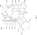
- Fig. 3 shows a further variant of a cleaning device 300.
- the cleaning device 300 comprises a carrier section 302, a cleaning section 304 attached thereto, a cleaning tool arranged on the cleaning section 204 (in Fig. 3 not shown) and a drive module 306.
- the carrier section 302 has, according to the Fig. 3
- the carrier section 302 has a fastening part 308 designed as a fastening plate for fastening to a transport device 122, the system component 102 or to a third object.
- the carrier section 302 has a movement device 310 mounted on the fastening part 308, which in the present variant is designed as a linear guide device 310 and serves to move the cleaning section 304 attached to the linear guide device 310 relative to the system component 102.
- the system component 102 can be, as in Fig. 3 As shown, this is a cellular wheel 112 of a rotary valve 102.
- the linear guide device 310 comprises two linear guides 312 arranged perpendicular to one another, each with guide rods and a drive. This allows the cleaning section 304 to be adjusted both vertically and horizontally and moved relative to the cellular wheel 112.
- the cleaning section 304 is designed to enclose the rotary valve 112 of the rotary valve 102 in a cleaning chamber 314.
- the cleaning section 304 is designed as a housing 316, here as a cylinder housing or drum, such that an interior of the housing 316 defines or forms the cleaning chamber 314.
- the housing 316 is open on one side, through which the cellular wheel 112 can enter the cleaning chamber.
- the cleaning section 304 is thus a type of cleaning or washing drum and forms a housing for the cellular wheel 112 for cleaning purposes.
- the cleaning tool projects into the cleaning chamber 314 and can be driven, for example, by means of a first drive of the drive module 306, to carry out a cleaning operation.
- a plurality of spray nozzles 318 opening into the cleaning chamber 314 are also arranged on the housing 316.
- an auxiliary substance e.g. cleaning agent, water or air, but also a rinsing agent
- supply lines 320 are provided, which are connected to the spray nozzles 318.
- discharge lines 322 are provided for discharging a contaminant, which are preferably arranged near the bottom of the housing 316 and lead with one end into the cleaning chamber 314.
- the housing 316 of the cleaning section 304 can now be moved by means of the linear guide device 310 and, if necessary, by means of the transport device 122 in such a way that the rotary valve 112 is guided into the cleaning chamber 314 and enclosed.
- the side cover 324, on which the rotary valve 122 is mounted comes into contact with the housing 316 of the cleaning section 304.
- the housing opening thereby tightly sealed.
- a flange part and/or a sealing element can be provided on the housing 316.
- the cell wheel 112 is now enclosed in the cleaning chamber 314, and the cleaning process for cleaning the cell wheel 112 using the cleaning tool and the spray nozzles 318 can begin.
- the cell wheel 112 can be designed so that it can be coupled to a second drive of the drive module 306.
- the cell wheel 112 can thus be driven by the second drive of the drive module 306 and set in rotation within the cleaning chamber 314. The cleaning performance is thereby further improved.
- Fig. 4 shows a further variant of a cleaning tool 400.
- the cleaning tool 400 can, for example, be arranged on the cleaning sections described above.
- the cleaning tool 400 comprises a brush device 402 and a suction device 404.
- the brush device 402 is designed to clean the system component or a part thereof.
- the brush device 402 has a carrier element 406 and a brush element 408 mounted thereon so as to be rotatable and/or pivotable.
- the brush element 408 is designed as a rotatable brush and comprises a rotatable disk 410, on the circumference of which the bristles 412 of the brush are arranged.
- the brush element 408 or its disk 410 can be driven by means of a drive (in Fig. 4 not shown).
- the suction device 404 is arranged on the carrier element 406 in such a way that a suction opening 414 of the suction device 404 faces the brush element 408.
- the suction device 404 is designed to suction the contaminant.
- the cleaning tool 400 is movable (in Fig. 4
- a drive and/or actuator can be provided.
- the cleaning tool 400 can thus, for example, be retracted into the interior of the housing of the rotary valve 102 or moved towards the rotary valve 112 of the rotary valve 102.
- the interior of the housing of the The rotary valve 102 or the rotary valve 112 can be easily cleaned by means of the rotating brush element 408 and the resulting dirt can be sucked away by means of the suction device 404 during the cleaning process.
- isolated features can also be selected from the combinations of features disclosed here and used in combination with other features to define the subject matter of the claim, dissolving any structural and/or functional connection that may exist between the features.
Landscapes
- Engineering & Computer Science (AREA)
- Mechanical Engineering (AREA)
- Cleaning In General (AREA)
Applications Claiming Priority (1)
| Application Number | Priority Date | Filing Date | Title |
|---|---|---|---|
| DE102023134325.4A DE102023134325A1 (de) | 2023-12-07 | 2023-12-07 | Reinigungsvorrichtung zum Reinigen einer Anlagenkomponente, Reinigungssystem, Anordnung und Förderanlage |
Publications (1)
| Publication Number | Publication Date |
|---|---|
| EP4566730A1 true EP4566730A1 (fr) | 2025-06-11 |
Family
ID=93036903
Family Applications (1)
| Application Number | Title | Priority Date | Filing Date |
|---|---|---|---|
| EP24205245.4A Pending EP4566730A1 (fr) | 2023-12-07 | 2024-10-08 | Dispositif de nettoyage pour nettoyer un composant d'installation, système de nettoyage, agencement et installation de transport |
Country Status (4)
| Country | Link |
|---|---|
| US (1) | US20250187846A1 (fr) |
| EP (1) | EP4566730A1 (fr) |
| CN (1) | CN120115427A (fr) |
| DE (1) | DE102023134325A1 (fr) |
Citations (8)
| Publication number | Priority date | Publication date | Assignee | Title |
|---|---|---|---|---|
| US4948017A (en) * | 1988-05-27 | 1990-08-14 | Waeschle Maschinenfabrik Gmbh | Rotary feeder |
| WO2006034267A2 (fr) * | 2004-09-21 | 2006-03-30 | Vibre-Tech Llc | Dispositif et procede de nettoyage de convoyeur |
| US7077260B2 (en) * | 2004-06-29 | 2006-07-18 | Gerald Michael Saballus | Device for cleaning corrugator belts |
| EP3581083A1 (fr) * | 2018-06-15 | 2019-12-18 | Fraunhofer-Gesellschaft zur Förderung der angewandten Forschung e.V. | Système de nettoyage comportant un robot d'alimentation et des satellites de nettoyage et procédé de nettoyage |
| CN111215413A (zh) * | 2018-11-27 | 2020-06-02 | 秦皇岛烟草机械有限责任公司 | 一种高压水射流式清洗设备 |
| DE202019105761U1 (de) * | 2019-10-17 | 2021-01-20 | Treffler Maschinenbau Gmbh & Co. Kg | Fördervorrichtung und Mahlanlage |
| US11618635B1 (en) * | 2022-04-12 | 2023-04-04 | Crossford International, Llc | Conveyor belt cleaning device adapted with modular cleaning heads |
| DE102022203136A1 (de) * | 2022-03-30 | 2023-10-05 | Coperion Gmbh | Zellenradschleuse für Schüttgut und Verfahren zum automatisierten Freilegen eines Zellenrads einer derartigen Zellenradschleuse |
Family Cites Families (3)
| Publication number | Priority date | Publication date | Assignee | Title |
|---|---|---|---|---|
| IT1301697B1 (it) * | 1998-06-12 | 2000-07-07 | Cml Handling Technology S P A | Apparecchiatura per la pulitura dei tappetini rotanti in macchinesmistatrici e macchina smistatrice dotata di detta apperecchiatura. |
| DE102004057445A1 (de) * | 2004-11-24 | 2006-06-01 | Hauni Maschinenbau Ag | Vorrichtung zum kontaktlosen Reinigen eines Förderelementes und Anordnung zum Transportieren und/oder Speichern stabförmiger Artikel mit einer Vorrichtung zum kontaktlosen Reinigen eines Förderelementes |
| DE102022105388B4 (de) * | 2022-03-08 | 2025-07-03 | HDG - Verpackungsmaschinen GmbH | Vorrichtung zum Austragen und/oder Dosieren von Material sowie ein Verfahren zur zumindest teilweisen Demontage einer solchen Vorrichtung |
-
2023
- 2023-12-07 DE DE102023134325.4A patent/DE102023134325A1/de active Pending
-
2024
- 2024-10-08 EP EP24205245.4A patent/EP4566730A1/fr active Pending
- 2024-11-28 CN CN202411721950.3A patent/CN120115427A/zh active Pending
- 2024-12-05 US US18/969,581 patent/US20250187846A1/en active Pending
Patent Citations (8)
| Publication number | Priority date | Publication date | Assignee | Title |
|---|---|---|---|---|
| US4948017A (en) * | 1988-05-27 | 1990-08-14 | Waeschle Maschinenfabrik Gmbh | Rotary feeder |
| US7077260B2 (en) * | 2004-06-29 | 2006-07-18 | Gerald Michael Saballus | Device for cleaning corrugator belts |
| WO2006034267A2 (fr) * | 2004-09-21 | 2006-03-30 | Vibre-Tech Llc | Dispositif et procede de nettoyage de convoyeur |
| EP3581083A1 (fr) * | 2018-06-15 | 2019-12-18 | Fraunhofer-Gesellschaft zur Förderung der angewandten Forschung e.V. | Système de nettoyage comportant un robot d'alimentation et des satellites de nettoyage et procédé de nettoyage |
| CN111215413A (zh) * | 2018-11-27 | 2020-06-02 | 秦皇岛烟草机械有限责任公司 | 一种高压水射流式清洗设备 |
| DE202019105761U1 (de) * | 2019-10-17 | 2021-01-20 | Treffler Maschinenbau Gmbh & Co. Kg | Fördervorrichtung und Mahlanlage |
| DE102022203136A1 (de) * | 2022-03-30 | 2023-10-05 | Coperion Gmbh | Zellenradschleuse für Schüttgut und Verfahren zum automatisierten Freilegen eines Zellenrads einer derartigen Zellenradschleuse |
| US11618635B1 (en) * | 2022-04-12 | 2023-04-04 | Crossford International, Llc | Conveyor belt cleaning device adapted with modular cleaning heads |
Also Published As
| Publication number | Publication date |
|---|---|
| CN120115427A (zh) | 2025-06-10 |
| DE102023134325A1 (de) | 2025-06-12 |
| US20250187846A1 (en) | 2025-06-12 |
Similar Documents
| Publication | Publication Date | Title |
|---|---|---|
| EP3581083B1 (fr) | Système de nettoyage comportant un robot d'alimentation et des satellites de nettoyage et procédé de nettoyage | |
| EP3076843B1 (fr) | Appareil de nettoyage du sol autotracté et autodirecteur et système de nettoyage | |
| EP3409165B1 (fr) | Dispositif de support sur un robot de nettoyage | |
| EP1372868B1 (fr) | Installation pour le peinturage a la poudre d'objets | |
| DE68908878T2 (de) | Vielseitige funktionelle vorrichtung zum reinigen im abstand und behandeln von flächen und gegenständen entlang den strassenrändern. | |
| DE102020119345B4 (de) | Wechselstation für Reinigungstücher und Verfahren zum Wechseln von Reinigungstüchern | |
| DE60000348T2 (de) | Anlage zum entfernen von streu und zum wiederfüllen von tierkäfigen | |
| EP4710832A2 (fr) | Appareil de nettoyage de sol avec élément de raclage mobile | |
| DE102014101969A1 (de) | Reinigungsmaschine | |
| EP3552715B1 (fr) | Installation de revêtement par poudre pourvue d'accouplement et procédé de nettoyage du système de revêtement par poudre | |
| EP3552716B1 (fr) | Dispositif de transport destiné au transport de la poudre de revêtement, centre d'alimentation en poudre pourvu d'appareil de transport et procédé de nettoyage du centre d'alimentation en poudre | |
| EP4250910A1 (fr) | Dispositif de ramassage d'excréments d`animaux | |
| DE102011006038A1 (de) | Schälautomat für langgestrecktes Schälgut | |
| DE102018116225A1 (de) | Reinigungsgerät | |
| DE202022101312U1 (de) | Bodenreinigungsgerät mit Kassette | |
| EP4566730A1 (fr) | Dispositif de nettoyage pour nettoyer un composant d'installation, système de nettoyage, agencement et installation de transport | |
| DE102023136194A1 (de) | Flächenbehandlungssystem | |
| DE102023136195A1 (de) | Flächenbehandlungssystem | |
| EP3552713B1 (fr) | Centre d'alimentation en poudre destiné à l'alimentation d'une installation de revêtement par poudre et procédé de nettoyage du centre d'alimentation en poudre | |
| EP3730020A1 (fr) | Robot pour le transport de robots de nettoyage autonomes | |
| EP2613893B1 (fr) | Système de nettoyage de contenants et procédé de nettoyage | |
| DE4331191A1 (de) | Kraftfahrzeug zum Transport von in Sammelbehältern gesammeltem Feststoffmaterial | |
| WO2022096256A1 (fr) | Unité d'alimentation agricole permettant un montage amovible sur un aéronef | |
| DE20020793U1 (de) | Vorrichtung zum Reinigen von Behältern, insbesondere zur Innenreinigung von Mülltonnen | |
| WO2024052397A1 (fr) | Robot de nettoyage pour le nettoyage de l'espace de chargement d'un moyen de transport |
Legal Events
| Date | Code | Title | Description |
|---|---|---|---|
| PUAI | Public reference made under article 153(3) epc to a published international application that has entered the european phase |
Free format text: ORIGINAL CODE: 0009012 |
|
| STAA | Information on the status of an ep patent application or granted ep patent |
Free format text: STATUS: THE APPLICATION HAS BEEN PUBLISHED |
|
| AK | Designated contracting states |
Kind code of ref document: A1 Designated state(s): AL AT BE BG CH CY CZ DE DK EE ES FI FR GB GR HR HU IE IS IT LI LT LU LV MC ME MK MT NL NO PL PT RO RS SE SI SK SM TR |
|
| STAA | Information on the status of an ep patent application or granted ep patent |
Free format text: STATUS: REQUEST FOR EXAMINATION WAS MADE |
|
| 17P | Request for examination filed |
Effective date: 20251210 |