EP4566743A1 - Foret aspirant et adaptateur d'aspiration - Google Patents
Foret aspirant et adaptateur d'aspiration Download PDFInfo
- Publication number
- EP4566743A1 EP4566743A1 EP23215115.9A EP23215115A EP4566743A1 EP 4566743 A1 EP4566743 A1 EP 4566743A1 EP 23215115 A EP23215115 A EP 23215115A EP 4566743 A1 EP4566743 A1 EP 4566743A1
- Authority
- EP
- European Patent Office
- Prior art keywords
- suction
- drill
- shaft
- cover element
- head
- Prior art date
- Legal status (The legal status is an assumption and is not a legal conclusion. Google has not performed a legal analysis and makes no representation as to the accuracy of the status listed.)
- Withdrawn
Links
Images


Classifications
-
- B—PERFORMING OPERATIONS; TRANSPORTING
- B23—MACHINE TOOLS; METAL-WORKING NOT OTHERWISE PROVIDED FOR
- B23B—TURNING; BORING
- B23B51/00—Tools for drilling machines
-
- B—PERFORMING OPERATIONS; TRANSPORTING
- B28—WORKING CEMENT, CLAY, OR STONE
- B28D—WORKING STONE OR STONE-LIKE MATERIALS
- B28D1/00—Working stone or stone-like materials, e.g. brick, concrete or glass, not provided for elsewhere; Machines, devices, tools therefor
- B28D1/14—Working stone or stone-like materials, e.g. brick, concrete or glass, not provided for elsewhere; Machines, devices, tools therefor by boring or drilling
- B28D1/146—Tools therefor
-
- B—PERFORMING OPERATIONS; TRANSPORTING
- B28—WORKING CEMENT, CLAY, OR STONE
- B28D—WORKING STONE OR STONE-LIKE MATERIALS
- B28D7/00—Accessories specially adapted for use with machines or devices of the preceding groups
- B28D7/02—Accessories specially adapted for use with machines or devices of the preceding groups for removing or laying dust, e.g. by spraying liquids; for cooling work
-
- B—PERFORMING OPERATIONS; TRANSPORTING
- B23—MACHINE TOOLS; METAL-WORKING NOT OTHERWISE PROVIDED FOR
- B23B—TURNING; BORING
- B23B2226/00—Materials of tools or workpieces not comprising a metal
- B23B2226/75—Stone, rock or concrete
-
- B—PERFORMING OPERATIONS; TRANSPORTING
- B23—MACHINE TOOLS; METAL-WORKING NOT OTHERWISE PROVIDED FOR
- B23B—TURNING; BORING
- B23B2251/00—Details of tools for drilling machines
- B23B2251/40—Flutes, i.e. chip conveying grooves
- B23B2251/4012—Flutes with sleeves
-
- B—PERFORMING OPERATIONS; TRANSPORTING
- B23—MACHINE TOOLS; METAL-WORKING NOT OTHERWISE PROVIDED FOR
- B23B—TURNING; BORING
- B23B2251/00—Details of tools for drilling machines
- B23B2251/68—Drills with provision for suction
Definitions
- the invention relates to a suction drill for drilling rock.
- the suction drill comprises a shaft, a drill head connected to the shaft, and a shank.
- the object of the present invention is therefore to present a suction drill and further devices for using the suction drill, which enable efficient and comfortable drilling in rock.
- a suction drill for drilling rock comprising a shaft, a drill head and an insertion end, wherein at least one groove is formed along the drill head and along the shaft, wherein the grooves in the drill head and in the shaft are at least partially covered by at least one cover element.
- the invention is based on the idea that drilling efficiency in rock can be increased by minimizing the amount of control required.
- attempts can be made to minimize drilling dust throughout the entire drilling process. particularly at the beginning of the drilling process.
- attempts can be made to create suction openings as close to the tip of the drill head as possible.
- the cross-section of the suction openings should be as large as possible in order to enable the lowest possible suction resistance and to be able to suction off larger particles. Both aspects can be achieved with the present solution.
- the suction drill as a groove drill, which has suction openings in the form of grooves extending into the drill head, the suction opening can be provided with a large cross-section.
- the suction channel formed by the groove and the cover element also reaches right up to the tip of the drill head. This results in optimized suction power right from the start of the drilling process. Even drilling dust that arises directly when the drilling process is initiated can be captured and suctioned off by the suction channel. This ensures with great certainty that no drilling dust, or at most only a very small amount, remains in the borehole. Even anchors or dowels that otherwise require a separately cleaned drill hole, such as a chemical dowel, can usually be installed immediately after drilling.
- the drill head can be made of hard metal. It can be sintered. It can be welded and/or soldered to the shaft. It is also conceivable for the drill head to be connected to the shaft by means of a positive fit. In the latter case, it is conceivable for the drill head to be detachably fixed to the shaft, particularly detachably without tools.
- the cover element can have a head section and a shaft section.
- the maximum diameter of the shaft section can be smaller than the maximum diameter of the head section, ensuring that at least the cover element of the shaft section can rotate freely in the borehole during drilling. This can reduce friction losses during drilling. If necessary, smoothing of the borehole wall can also be avoided, eliminating the need for subsequent roughening.
- the drill head is sintered, it is conceivable to form at least one groove on the drill head by molding the green body of the drill head. This eliminates the need for additional machining steps, particularly drilling or milling into the hard metal of the drill head.
- At least one groove in the drill head can be aligned with at least one groove in the shaft.
- “Alignment” in this context means that both grooves run parallel to a longitudinal axis of the suction drill and merge into one another, regardless of whether the grooves extend at least partially at different distances from the longitudinal axis, i.e., at different radial distances from the longitudinal axis. Drill dust can thus be extracted straight across the entire suction channel, i.e., parallel to the longitudinal axis, allowing drilling dust to be extracted with low suction resistance.
- the cover element can be designed as a sleeve at least along the shaft.
- the sleeve can simply be slipped over the shaft, so that all grooves along the shaft can be easily covered by the sleeve.
- the cover element can have a lattice structure in at least one region.
- a plurality of grooves extending linearly and parallel to a longitudinal axis of the shaft can be formed on the shaft.
- Each of the grooves in the shaft can be covered by a partial element of the cover element and/or by a separate element of the cover element.
- the partial elements can then, in turn, be connected to one another.
- the cover element of the shaft can comprise several sub-elements.
- the cover element can be designed to cover the shaft only partially, rather than completely. This allows material to be saved. Friction during drilling, particularly between the cover element and a borehole wall, can be reduced or eliminated.
- a connecting ring extending radially around the shaft connects the individual sub-elements to one another and/or fixes them to the shaft.
- the sub-elements, together with the connecting ring can take the form of a ring-shaped mesh fence.
- the partial elements and/or the entire cover element run within a circumferential surface of the shaft.
- At least one of the grooves is lined with a tube.
- the cover element can line at least one of the grooves as a tube.
- at least one of the sub-elements can have a tubular shape.
- the sub-element and/or the cover element can, for example, be triangular in cross-section, in particular rounded-triangular.
- At least one section of the cover element can be made of a plastic. This is particularly advantageous if one of the measures described above is expected to result in only minimal friction between the cover element and the borehole wall.
- a suction adapter can be arranged on the shaft.
- the suction adapter can be used to guide the suction channel formed along the shaft to a suction nozzle of a suction system.
- the suction adapter can be connected to the rest of the shaft in a rotationally fixed manner.
- the suction adapter, together with the shaft, can rotate in the suction nozzle during drilling.
- the shaft can be rotatably mounted in the suction adapter.
- the suction adapter can have at least one radially circumferential groove.
- the groove allows the suction adapter and thus the suction drill to be mounted in the suction nozzle.
- the scope of the invention also includes a suction nozzle for a suction drill of the type described above and/or below.
- At least one elastic ring such as a rubber ring, can be located on the extraction nozzle.
- the elastic ring can serve as a seal between the extraction nozzle and the extraction adapter. It can itself be located in radial grooves in the extraction nozzle and/or the extraction adapter. This also prevents the suction drill from accidentally slipping out. from the suction nozzle.
- the extraction nozzle can preferably be designed without moving parts, making it particularly durable. It can be at least two-part. In particular, it can be formed from two halves, which can, for example, be designed to fit one another. The extraction drill, particularly together with the extraction adapter, can then be inserted into the extraction nozzle without the need for tools. The halves can be fitted onto one another. This eliminates the need for a separate locking mechanism, for example, to guide the extraction drill into the extraction nozzle and/or to secure it from slipping out.
- a chisel similar to a suction drill is also conceivable.
- One difference may be that a chisel head may be provided instead of a drill head.
- the chisel head may have a point-shaped tip.
- the chisel head may have a chisel blade.
- the scope of the invention further includes a machine tool, in particular a chiseling machine tool such as a hammer drill or a chiseling machine, for machining rock, with a suction nozzle in which a suction drill of the type described above and/or below is arranged.
- a machine tool in particular a chiseling machine tool such as a hammer drill or a chiseling machine, for machining rock, with a suction nozzle in which a suction drill of the type described above and/or below is arranged.
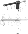
- Fig. 1 shows a suction drill 10 with a shaft 12, on which a drill head 14 is formed at one end and a plug-in end 16 at the other end.
- the suction drill 10 is connected to a suction nozzle 18 via a suction adapter 20.
- a suction connection 22 of the suction nozzle can be connected to a suction and/or blowing device for sucking out drilling dust and/or blowing out drill holes, for example.
- Fig. 2 shows a longitudinal sectional view of the suction drill 10 and the suction nozzle 18. It can be seen that the shaft 12 and the drill head 14 are at least partially covered by a cover element 24.
- the cover element 24 is formed in one piece in this embodiment.
- the cover element 24 has a head portion 26 and a shaft portion 28.
- the head portion 26 at least partially covers the drill head 14.
- the head portion 26 covers the drill head with the exception of cutting edges 30 and an end face 32.
- the shaft portion 28 covers the shaft 12 at least partially, in particular in a region between the drill head 14 and the suction nozzle. 18.
- a maximum diameter d1 of the shaft portion 28 is smaller than a maximum diameter d2 of the head portion 26.
- Grooves 34 are formed along the drill head 14, and grooves 36 are formed in the shaft 12.
- the grooves 34 in the drill head 14 and the grooves 36 in the shaft 12 are at least partially covered by the cover element 24.
- suction channels 38 are formed between the cover element 24 and the shaft 12.
- the grooves 34, 36 and thus the suction channels 38 run, apart from varying radial distances, parallel to a longitudinal axis L of the shaft 12 and the drill head 14.
- the grooves 34 of the drill head 14 are each aligned with corresponding grooves 36 of the shaft 12.
- the drill head 14 is sintered from a tungsten-containing hard metal.
- the grooves 34 on the drill head 14 were already formed in the green part of the drill head 14 before sintering into a brown part.
- the cover element 24 is designed as a sleeve at least along the shaft 12. It is formed in one piece and, in particular, from a plastic material.
- FIG. 3 An enlarged detailed view of area III from Fig. 2 shows Fig. 3 .
- the suction channels 38 of which again, for the sake of simplicity, only one is shown in Fig. 3 is provided with a reference symbol, open via connecting openings 40 in the suction adapter 20 into a collecting chamber 42 of the suction nozzle 18.
- the collecting chamber 42 is in turn connected to the suction connection 22, so that drilling dust is drawn along the suction channels 38 into the collecting chamber 42 and from there into a suction device connected to the suction connection 22, which in Fig. 3 not shown, can be removed.
- the suction adapter 20 is connected to the shaft 12 in a rotationally fixed manner.
- a radially encircling O-ring 44 is located between the suction adapter 20 and the cover element 24.
- An elastic ring 46 in the form of a rubber ring sits in radially encircling grooves 48 and 50 of the suction adapter and the suction nozzle 18, respectively.
- the extraction adapter 20 does not require any movable, for example, longitudinally displaceable, part.
- the extraction nozzle 18 also does not require any movable, for example, longitudinally displaceable, part.
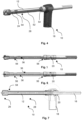
- Fig. 4 shows another embodiment of a suction drill 10 connected to a suction nozzle 18. Unless otherwise described, one or more features of this embodiment may correspond to those of the previously described embodiment.
- the cover element 24 has a grid structure at least in one area and is therefore not designed as a sleeve. It has sub-elements 52 that form the grooves 36 (see Fig. 5 ) of the shaft section 28 individually. To simplify the illustration, Fig. 4 only one of the sub-elements 52 is provided with a reference symbol.
- the sub-elements 52 are held to the shaft 12 and thus to each other by radially encircling connecting rings 54.
- the sub-elements 52 are connected to one another via the connecting rings 54.
- the sub-elements 52 and the connecting rings 54 can be formed as a single-piece cover element 24.
- At least one of the sub-elements 52 may comprise a plastic.
- Fig. 5 and Fig. 6 which each show perspective side views of the suction drill 10 without cover element 24, but with suction adapter 20, from different viewing directions, show that two radial grooves 56 are formed in the shaft 12, so that the connecting rings 54 (see Fig. 4 ) can sit in them. This way, the cover element 24 can be secured against displacement.
- Fig. 7 shows a longitudinal sectional view of this embodiment and the associated suction nozzle 18.
- the suction drill 10 is in this respect very similar to the previously described embodiments.
- a transition region 58 between the head section 26 and the shaft section 28 is formed steeper than in the embodiment according to Fig. 2 .
- Fig. 8 and Fig. 9 show cross sections of the shaft section 28 of the embodiment according to Fig. 1 or according to Fig. 4 .
- the cover element 24 forms a sleeve in the area of the shaft section 28 and thereby covers all the grooves 36 of the shaft section 28.
- each of the sub-elements 52 lines one of the grooves 36 of the shaft section 28.
- each of the sub-elements 52 is designed as a tube with a rounded-triangular cross-section.
- an outer radius r1 of the sub-elements 52 is smaller than a maximum radius r2 of the shaft 12.
- the sub-elements 52 are thus preferably located within the circumferential circle inscribed by the shaft 12.
Landscapes
- Engineering & Computer Science (AREA)
- Mechanical Engineering (AREA)
- Mining & Mineral Resources (AREA)
- Processing Of Stones Or Stones Resemblance Materials (AREA)
Priority Applications (1)
| Application Number | Priority Date | Filing Date | Title |
|---|---|---|---|
| EP23215115.9A EP4566743A1 (fr) | 2023-12-08 | 2023-12-08 | Foret aspirant et adaptateur d'aspiration |
Applications Claiming Priority (1)
| Application Number | Priority Date | Filing Date | Title |
|---|---|---|---|
| EP23215115.9A EP4566743A1 (fr) | 2023-12-08 | 2023-12-08 | Foret aspirant et adaptateur d'aspiration |
Publications (1)
| Publication Number | Publication Date |
|---|---|
| EP4566743A1 true EP4566743A1 (fr) | 2025-06-11 |
Family
ID=89222549
Family Applications (1)
| Application Number | Title | Priority Date | Filing Date |
|---|---|---|---|
| EP23215115.9A Withdrawn EP4566743A1 (fr) | 2023-12-08 | 2023-12-08 | Foret aspirant et adaptateur d'aspiration |
Country Status (1)
| Country | Link |
|---|---|
| EP (1) | EP4566743A1 (fr) |
Citations (4)
| Publication number | Priority date | Publication date | Assignee | Title |
|---|---|---|---|---|
| EP0891238B1 (fr) * | 1996-03-27 | 2001-05-16 | KOMET Präzisionswerkzeuge Robert Breuning GmbH | Outil de percage pour machines-outils et procede permettant de la produire |
| DE102017219452A1 (de) * | 2017-10-30 | 2019-05-02 | Robert Bosch Gmbh | Bohrwerkzeug |
| DE102021204594A1 (de) * | 2021-05-06 | 2022-11-10 | Robert Bosch Gesellschaft mit beschränkter Haftung | Bohrwerkzeug |
| DE102021204606A1 (de) | 2021-05-06 | 2022-11-10 | Robert Bosch Gesellschaft mit beschränkter Haftung | Absaugadapter |
-
2023
- 2023-12-08 EP EP23215115.9A patent/EP4566743A1/fr not_active Withdrawn
Patent Citations (4)
| Publication number | Priority date | Publication date | Assignee | Title |
|---|---|---|---|---|
| EP0891238B1 (fr) * | 1996-03-27 | 2001-05-16 | KOMET Präzisionswerkzeuge Robert Breuning GmbH | Outil de percage pour machines-outils et procede permettant de la produire |
| DE102017219452A1 (de) * | 2017-10-30 | 2019-05-02 | Robert Bosch Gmbh | Bohrwerkzeug |
| DE102021204594A1 (de) * | 2021-05-06 | 2022-11-10 | Robert Bosch Gesellschaft mit beschränkter Haftung | Bohrwerkzeug |
| DE102021204606A1 (de) | 2021-05-06 | 2022-11-10 | Robert Bosch Gesellschaft mit beschränkter Haftung | Absaugadapter |
Similar Documents
| Publication | Publication Date | Title |
|---|---|---|
| DE2945766C2 (de) | Bohrkrone und Bohrwerkzeug mit einer solchen Bohrkrone | |
| EP0854773B1 (fr) | Outil inserable et porte-outil pour machines electriques a percer et/ou percutantes | |
| DE8630241U1 (de) | Bohrer | |
| DE102007050050A1 (de) | Rundlaufwerkzeug, insbesondere Bohrer | |
| DE102014212714A1 (de) | Bohrerkopf | |
| DE69816857T2 (de) | Fräswerkzeug zur verwendung in einem bohrloch und fräsverfahren | |
| EP3656494B1 (fr) | Foret étagé | |
| DE1608268B2 (de) | Gesteinsbohrwerkzeug | |
| AT15689U1 (de) | Bohrkopf und Bohrwerkzeug | |
| DE112008000158T5 (de) | Bohrspitze und Einzeldurchlauf-Bohrvorrichtung | |
| EP0717666B1 (fr) | Porte-brosse reglable en continu | |
| DE3208844C2 (fr) | ||
| DE3783699T2 (de) | Drehbohrwerkzeug mit einem ausstellbaren raeumer. | |
| DE3501860C2 (de) | Bohrvorrichtung mit Absaugsystem | |
| DE3206678C2 (de) | Bohrwerkzeug zum Erzeugen eines Hinterschnittes in einer in Stein, Mauerwerk o.dgl. vorgebohrten zylindrischen Sacklochbohrung | |
| AT411567B (de) | Bohrer zur herstellung von bohrungen in einem knochengewebe | |
| DE3423789C2 (de) | Bohreinrichtung für Gesteinsbohrungen | |
| DE1811202A1 (de) | Bohrer | |
| DE102007025745B4 (de) | Werkzeugsatz, Bohrer und Verfahren zum Ausbohren von defekten Glühkerzen | |
| DE2723785B2 (de) | Borhwerkzeug | |
| DE3346440C2 (de) | Bohrfutter, insbesondere Hammerbohrfutter | |
| DE3873358T2 (de) | Selbsteinstellbarer korb fuer bohrmeissel. | |
| DE69423471T2 (de) | Auswechselbares Schneidmittelsegment für einen Bohrmeissel | |
| EP1122013B1 (fr) | Trépan de forage | |
| EP4621187A1 (fr) | Outil de burinage modulaire |
Legal Events
| Date | Code | Title | Description |
|---|---|---|---|
| PUAI | Public reference made under article 153(3) epc to a published international application that has entered the european phase |
Free format text: ORIGINAL CODE: 0009012 |
|
| STAA | Information on the status of an ep patent application or granted ep patent |
Free format text: STATUS: THE APPLICATION HAS BEEN PUBLISHED |
|
| AK | Designated contracting states |
Kind code of ref document: A1 Designated state(s): AL AT BE BG CH CY CZ DE DK EE ES FI FR GB GR HR HU IE IS IT LI LT LU LV MC ME MK MT NL NO PL PT RO RS SE SI SK SM TR |
|
| STAA | Information on the status of an ep patent application or granted ep patent |
Free format text: STATUS: THE APPLICATION IS DEEMED TO BE WITHDRAWN |
|
| 18D | Application deemed to be withdrawn |
Effective date: 20251212 |