EP4567090A1 - Procédé et dispositif pour la décomposition de combustibles par décomposition thermique par oxydation partielle - Google Patents
Procédé et dispositif pour la décomposition de combustibles par décomposition thermique par oxydation partielle Download PDFInfo
- Publication number
- EP4567090A1 EP4567090A1 EP23214247.1A EP23214247A EP4567090A1 EP 4567090 A1 EP4567090 A1 EP 4567090A1 EP 23214247 A EP23214247 A EP 23214247A EP 4567090 A1 EP4567090 A1 EP 4567090A1
- Authority
- EP
- European Patent Office
- Prior art keywords
- reactor
- fuel
- fuel gas
- recirculation system
- inlet section
- Prior art date
- Legal status (The legal status is an assumption and is not a legal conclusion. Google has not performed a legal analysis and makes no representation as to the accuracy of the status listed.)
- Pending
Links
Images

Classifications
-
- C—CHEMISTRY; METALLURGY
- C10—PETROLEUM, GAS OR COKE INDUSTRIES; TECHNICAL GASES CONTAINING CARBON MONOXIDE; FUELS; LUBRICANTS; PEAT
- C10B—DESTRUCTIVE DISTILLATION OF CARBONACEOUS MATERIALS FOR PRODUCTION OF GAS, COKE, TAR, OR SIMILAR MATERIALS
- C10B7/00—Coke ovens with mechanical conveying means for the raw material inside the oven
- C10B7/10—Coke ovens with mechanical conveying means for the raw material inside the oven with conveyor-screws
-
- C—CHEMISTRY; METALLURGY
- C10—PETROLEUM, GAS OR COKE INDUSTRIES; TECHNICAL GASES CONTAINING CARBON MONOXIDE; FUELS; LUBRICANTS; PEAT
- C10B—DESTRUCTIVE DISTILLATION OF CARBONACEOUS MATERIALS FOR PRODUCTION OF GAS, COKE, TAR, OR SIMILAR MATERIALS
- C10B49/00—Destructive distillation of solid carbonaceous materials by direct heating with heat-carrying agents including the partial combustion of the solid material to be treated
- C10B49/02—Destructive distillation of solid carbonaceous materials by direct heating with heat-carrying agents including the partial combustion of the solid material to be treated with hot gases or vapours, e.g. hot gases obtained by partial combustion of the charge
- C10B49/04—Destructive distillation of solid carbonaceous materials by direct heating with heat-carrying agents including the partial combustion of the solid material to be treated with hot gases or vapours, e.g. hot gases obtained by partial combustion of the charge while moving the solid material to be treated
-
- C—CHEMISTRY; METALLURGY
- C10—PETROLEUM, GAS OR COKE INDUSTRIES; TECHNICAL GASES CONTAINING CARBON MONOXIDE; FUELS; LUBRICANTS; PEAT
- C10B—DESTRUCTIVE DISTILLATION OF CARBONACEOUS MATERIALS FOR PRODUCTION OF GAS, COKE, TAR, OR SIMILAR MATERIALS
- C10B53/00—Destructive distillation, specially adapted for particular solid raw materials or solid raw materials in special form
-
- C—CHEMISTRY; METALLURGY
- C10—PETROLEUM, GAS OR COKE INDUSTRIES; TECHNICAL GASES CONTAINING CARBON MONOXIDE; FUELS; LUBRICANTS; PEAT
- C10B—DESTRUCTIVE DISTILLATION OF CARBONACEOUS MATERIALS FOR PRODUCTION OF GAS, COKE, TAR, OR SIMILAR MATERIALS
- C10B53/00—Destructive distillation, specially adapted for particular solid raw materials or solid raw materials in special form
- C10B53/02—Destructive distillation, specially adapted for particular solid raw materials or solid raw materials in special form of cellulose-containing material
-
- C—CHEMISTRY; METALLURGY
- C10—PETROLEUM, GAS OR COKE INDUSTRIES; TECHNICAL GASES CONTAINING CARBON MONOXIDE; FUELS; LUBRICANTS; PEAT
- C10J—PRODUCTION OF PRODUCER GAS, WATER-GAS, SYNTHESIS GAS FROM SOLID CARBONACEOUS MATERIAL, OR MIXTURES CONTAINING THESE GASES; CARBURETTING AIR OR OTHER GASES
- C10J3/00—Production of combustible gases containing carbon monoxide from solid carbonaceous fuels
- C10J3/007—Screw type gasifiers
-
- C—CHEMISTRY; METALLURGY
- C10—PETROLEUM, GAS OR COKE INDUSTRIES; TECHNICAL GASES CONTAINING CARBON MONOXIDE; FUELS; LUBRICANTS; PEAT
- C10J—PRODUCTION OF PRODUCER GAS, WATER-GAS, SYNTHESIS GAS FROM SOLID CARBONACEOUS MATERIAL, OR MIXTURES CONTAINING THESE GASES; CARBURETTING AIR OR OTHER GASES
- C10J3/00—Production of combustible gases containing carbon monoxide from solid carbonaceous fuels
- C10J3/72—Other features
- C10J3/723—Controlling or regulating the gasification process
-
- C—CHEMISTRY; METALLURGY
- C10—PETROLEUM, GAS OR COKE INDUSTRIES; TECHNICAL GASES CONTAINING CARBON MONOXIDE; FUELS; LUBRICANTS; PEAT
- C10K—PURIFYING OR MODIFYING THE CHEMICAL COMPOSITION OF COMBUSTIBLE GASES CONTAINING CARBON MONOXIDE
- C10K1/00—Purifying combustible gases containing carbon monoxide
- C10K1/02—Dust removal
- C10K1/026—Dust removal by centrifugal forces
-
- C—CHEMISTRY; METALLURGY
- C10—PETROLEUM, GAS OR COKE INDUSTRIES; TECHNICAL GASES CONTAINING CARBON MONOXIDE; FUELS; LUBRICANTS; PEAT
- C10L—FUELS NOT OTHERWISE PROVIDED FOR; NATURAL GAS; SYNTHETIC NATURAL GAS OBTAINED BY PROCESSES NOT COVERED BY SUBCLASSES C10G OR C10K; LIQUIFIED PETROLEUM GAS; USE OF ADDITIVES TO FUELS OR FIRES; FIRE-LIGHTERS
- C10L3/00—Gaseous fuels; Natural gas; Synthetic natural gas obtained by processes not covered by subclass C10G, C10K; Liquefied petroleum gas
- C10L3/06—Natural gas; Synthetic natural gas obtained by processes not covered by C10G, C10K3/02 or C10K3/04
- C10L3/08—Production of synthetic natural gas
-
- C—CHEMISTRY; METALLURGY
- C10—PETROLEUM, GAS OR COKE INDUSTRIES; TECHNICAL GASES CONTAINING CARBON MONOXIDE; FUELS; LUBRICANTS; PEAT
- C10B—DESTRUCTIVE DISTILLATION OF CARBONACEOUS MATERIALS FOR PRODUCTION OF GAS, COKE, TAR, OR SIMILAR MATERIALS
- C10B49/00—Destructive distillation of solid carbonaceous materials by direct heating with heat-carrying agents including the partial combustion of the solid material to be treated
- C10B49/02—Destructive distillation of solid carbonaceous materials by direct heating with heat-carrying agents including the partial combustion of the solid material to be treated with hot gases or vapours, e.g. hot gases obtained by partial combustion of the charge
- C10B49/04—Destructive distillation of solid carbonaceous materials by direct heating with heat-carrying agents including the partial combustion of the solid material to be treated with hot gases or vapours, e.g. hot gases obtained by partial combustion of the charge while moving the solid material to be treated
- C10B49/06—Destructive distillation of solid carbonaceous materials by direct heating with heat-carrying agents including the partial combustion of the solid material to be treated with hot gases or vapours, e.g. hot gases obtained by partial combustion of the charge while moving the solid material to be treated according to the moving bed type
-
- C—CHEMISTRY; METALLURGY
- C10—PETROLEUM, GAS OR COKE INDUSTRIES; TECHNICAL GASES CONTAINING CARBON MONOXIDE; FUELS; LUBRICANTS; PEAT
- C10J—PRODUCTION OF PRODUCER GAS, WATER-GAS, SYNTHESIS GAS FROM SOLID CARBONACEOUS MATERIAL, OR MIXTURES CONTAINING THESE GASES; CARBURETTING AIR OR OTHER GASES
- C10J2200/00—Details of gasification apparatus
- C10J2200/15—Details of feeding means
- C10J2200/158—Screws
-
- C—CHEMISTRY; METALLURGY
- C10—PETROLEUM, GAS OR COKE INDUSTRIES; TECHNICAL GASES CONTAINING CARBON MONOXIDE; FUELS; LUBRICANTS; PEAT
- C10J—PRODUCTION OF PRODUCER GAS, WATER-GAS, SYNTHESIS GAS FROM SOLID CARBONACEOUS MATERIAL, OR MIXTURES CONTAINING THESE GASES; CARBURETTING AIR OR OTHER GASES
- C10J2300/00—Details of gasification processes
- C10J2300/09—Details of the feed, e.g. feeding of spent catalyst, inert gas or halogens
- C10J2300/0913—Carbonaceous raw material
- C10J2300/0916—Biomass
-
- C—CHEMISTRY; METALLURGY
- C10—PETROLEUM, GAS OR COKE INDUSTRIES; TECHNICAL GASES CONTAINING CARBON MONOXIDE; FUELS; LUBRICANTS; PEAT
- C10J—PRODUCTION OF PRODUCER GAS, WATER-GAS, SYNTHESIS GAS FROM SOLID CARBONACEOUS MATERIAL, OR MIXTURES CONTAINING THESE GASES; CARBURETTING AIR OR OTHER GASES
- C10J2300/00—Details of gasification processes
- C10J2300/09—Details of the feed, e.g. feeding of spent catalyst, inert gas or halogens
- C10J2300/0953—Gasifying agents
- C10J2300/0959—Oxygen
-
- C—CHEMISTRY; METALLURGY
- C10—PETROLEUM, GAS OR COKE INDUSTRIES; TECHNICAL GASES CONTAINING CARBON MONOXIDE; FUELS; LUBRICANTS; PEAT
- C10J—PRODUCTION OF PRODUCER GAS, WATER-GAS, SYNTHESIS GAS FROM SOLID CARBONACEOUS MATERIAL, OR MIXTURES CONTAINING THESE GASES; CARBURETTING AIR OR OTHER GASES
- C10J2300/00—Details of gasification processes
- C10J2300/12—Heating the gasifier
- C10J2300/1253—Heating the gasifier by injecting hot gas
-
- C—CHEMISTRY; METALLURGY
- C10—PETROLEUM, GAS OR COKE INDUSTRIES; TECHNICAL GASES CONTAINING CARBON MONOXIDE; FUELS; LUBRICANTS; PEAT
- C10J—PRODUCTION OF PRODUCER GAS, WATER-GAS, SYNTHESIS GAS FROM SOLID CARBONACEOUS MATERIAL, OR MIXTURES CONTAINING THESE GASES; CARBURETTING AIR OR OTHER GASES
- C10J2300/00—Details of gasification processes
- C10J2300/18—Details of the gasification process, e.g. loops, autothermal operation
- C10J2300/1807—Recycle loops, e.g. gas, solids, heating medium, water
-
- C—CHEMISTRY; METALLURGY
- C10—PETROLEUM, GAS OR COKE INDUSTRIES; TECHNICAL GASES CONTAINING CARBON MONOXIDE; FUELS; LUBRICANTS; PEAT
- C10J—PRODUCTION OF PRODUCER GAS, WATER-GAS, SYNTHESIS GAS FROM SOLID CARBONACEOUS MATERIAL, OR MIXTURES CONTAINING THESE GASES; CARBURETTING AIR OR OTHER GASES
- C10J2300/00—Details of gasification processes
- C10J2300/18—Details of the gasification process, e.g. loops, autothermal operation
- C10J2300/1846—Partial oxidation, i.e. injection of air or oxygen only
-
- C—CHEMISTRY; METALLURGY
- C10—PETROLEUM, GAS OR COKE INDUSTRIES; TECHNICAL GASES CONTAINING CARBON MONOXIDE; FUELS; LUBRICANTS; PEAT
- C10L—FUELS NOT OTHERWISE PROVIDED FOR; NATURAL GAS; SYNTHETIC NATURAL GAS OBTAINED BY PROCESSES NOT COVERED BY SUBCLASSES C10G OR C10K; LIQUIFIED PETROLEUM GAS; USE OF ADDITIVES TO FUELS OR FIRES; FIRE-LIGHTERS
- C10L2290/00—Fuel preparation or upgrading, processes or apparatus therefore, comprising specific process steps or apparatus units
- C10L2290/02—Combustion or pyrolysis
-
- C—CHEMISTRY; METALLURGY
- C10—PETROLEUM, GAS OR COKE INDUSTRIES; TECHNICAL GASES CONTAINING CARBON MONOXIDE; FUELS; LUBRICANTS; PEAT
- C10L—FUELS NOT OTHERWISE PROVIDED FOR; NATURAL GAS; SYNTHETIC NATURAL GAS OBTAINED BY PROCESSES NOT COVERED BY SUBCLASSES C10G OR C10K; LIQUIFIED PETROLEUM GAS; USE OF ADDITIVES TO FUELS OR FIRES; FIRE-LIGHTERS
- C10L5/00—Solid fuels
- C10L5/02—Solid fuels such as briquettes consisting mainly of carbonaceous materials of mineral or non-mineral origin
-
- C—CHEMISTRY; METALLURGY
- C10—PETROLEUM, GAS OR COKE INDUSTRIES; TECHNICAL GASES CONTAINING CARBON MONOXIDE; FUELS; LUBRICANTS; PEAT
- C10L—FUELS NOT OTHERWISE PROVIDED FOR; NATURAL GAS; SYNTHETIC NATURAL GAS OBTAINED BY PROCESSES NOT COVERED BY SUBCLASSES C10G OR C10K; LIQUIFIED PETROLEUM GAS; USE OF ADDITIVES TO FUELS OR FIRES; FIRE-LIGHTERS
- C10L9/00—Treating solid fuels to improve their combustion
- C10L9/08—Treating solid fuels to improve their combustion by heat treatments, e.g. calcining
- C10L9/083—Torrefaction
Definitions
- the invention relates to a method and a device for splitting, in particular, moist fuels by thermal decomposition of the fuel into gaseous components (hereinafter referred to as "fuel gas”) and a solid, carbon-containing product (hereinafter referred to as "coal”) within a moving-bed reactor, as well as the optionally desired further treatment of the produced fuel gas into synthesis gas or flue gas and of the produced coal into activated carbon or ash.
- the method and device serve both in the sense of pyrolysis for the effective production of coal and in the sense of gasification for the effective production of fuel gas.
- the fuel to be split is thermally decomposed under the influence of high temperatures, preferably between approx. 300 °C and approx. 750 °C.
- high temperatures preferably between approx. 300 °C and approx. 750 °C.
- this thermal decomposition takes place in an oxygen-free or at least oxygen-poor atmosphere.
- the composition of the gaseous products formed consists of a variety of chemical compounds and depends on the fuels used and the process conditions. Typical compounds are CO, CO 2 , H 2 , H 2 O, CH 4 , C 2 H 4 , as well as a variety of other low molecular weight organic compounds, as well as higher molecular weight oils and tars, and coal.
- this decomposition takes place either in allothermal or autothermal reactors, or in hybrids of these two basic process variants.
- the allothermal process variant is characterized by the fact that the temperature required for the process is introduced into the reactor by external heat input (typically using the reactor wall as the heat transfer surface).
- the required heat energy is generated in the reactor itself. This occurs through partial combustion (partial oxidation).
- partial oxidation partial oxidation
- a portion of the fuel and/or combustible gases is oxidized or burned within the reactor by adding comparatively small amounts of oxidant.
- the major advantage of autothermal processing is that it avoids the transfer of large amounts of heat at a high temperature through the reactor wall, as is necessary in allothermal processing. Autothermal processing is therefore significantly less complex in terms of equipment, has a higher power density, and is therefore significantly more economical.
- the autothermal process stages implemented so far for splitting solid fuels into fuel gas and coal all have a technical shortcoming: the oxidant for the autothermal process is injected directly into the coal bed.
- the homogeneous oxidation reaction between fuel gas and oxidant proceeds much faster and preferentially than the heterogeneous oxidation reaction between the solid coal and the oxidant, the direct injection of the The introduction of an oxidizer into the coal bed leads to excessive coal consumption. This occurs because there is insufficient fuel gas in the coal bed, and therefore any locally present excess oxidizer oxidizes the coal. If the process aims to produce the largest possible quantities of coal, this process is therefore unsuitable.
- the EP 3 858 952 A1 proposes introducing an oxidizing agent into the gas chamber above the fuel bed via a plurality of nozzles distributed along the length of the reactor, thereby creating a desired temperature profile. While this process makes it possible to carbonize moist fuels with a water content of up to 40%, the throughput and carbonization efficiency, or rather the coal yield, are correspondingly lower for such moist fuels. According to the current state of the art, fuels with a water content of more than 40% must be dried beforehand.
- the present invention is therefore based on the problem of more efficiently autothermally splitting moist fuels with up to 45% water content in a very compact and simply constructed apparatus and thereby producing coal with a higher carbonisation efficiency without having to first dry the fuel in an upstream dryer.
- the process according to the invention enables more efficient autothermal decomposition of fuels with up to 45% water content, thereby producing coal with a higher carbonization efficiency without having to first dry the fuel in an upstream dryer.
- the required evaporation enthalpy can be provided from a portion of the chemical energy contained in the recirculated fuel gas. This prevents the reactor from cooling excessively due to evaporation, even with very moist fuels, but rather keeps the thermal decomposition running at substoichiometric rates.
- Ambient air is preferably used as the oxidant.
- oxidant can be fed into at least a portion of the extracted fuel gas in the recirculation system. This can occur at one or more points in the recirculation system, as required.
- oxidant By feeding in oxidant, a portion of the extracted fuel gas ignites automatically, provided its temperature is above the auto-ignition temperature.
- the auto-ignition of a portion of the extracted fuel gas increases the temperature of the extracted fuel gas, thus preventing the temperature of the extracted fuel gas in the recirculation system from falling below the auto-ignition temperature.
- the feed of oxidant can be metered and, if necessary, controlled by temperature measurement, so that only enough oxidant is fed in to ensure that the temperature of the extracted fuel gas in the recirculation system remains a certain degree above the auto-ignition temperature.
- the smaller the portion of the fuel gas that reacts with the oxidant in the recirculation system the greater the calorific value of the fuel gas that is returned to the reactor and can be diverted from the recirculation system into a fuel gas
- the reactor's exhaust point can be located in the reactor's inlet section, and the reactor's feed point in the reactor's outlet section. This is advantageous for several reasons.
- the water vapor content in the reactor's inlet section is particularly high.
- the exhaust in the inlet section creates a potentially advantageous fuel gas flow in the reactor opposite to the flow direction of the fuel bed.
- the reactor's exhaust point can be located in the reactor's outlet section, and the reactor's feed point can be located in the reactor's inlet section.
- the recirculation system can reverse the flow direction of the fuel gas through the recirculation system as needed, so that the exhaust point becomes the feed point, and vice versa.
- the extracted fuel gas can be dedusted in a dedusting system, with dedusting taking place using gravity, centrifugal force, and/or a filter in a separator. This is useful so that a portion of the fuel gas can be fed to a downstream fuel gas chamber for useful heat extraction with as little dust as possible.
- Oxidizing agent is preferably fed into the extracted fuel gas in the recirculation system before the temperature of the extracted fuel gas in the recirculation system falls below the auto-ignition temperature of the extracted fuel gas, in order to at least partially ignite it and thus heat it by the injected oxidizing agent.
- the fuel gas can be kept at a minimum temperature in the reactor at the extraction point that is sufficient to ensure that the fuel gas in the recirculation system does not fall below the auto-ignition temperature of the extracted fuel gas until the oxidizing agent is fed in. Fuel gas cools down. This eliminates the need to heat the fuel gas in the recirculation system upstream of the oxidant feed.
- oxidant can be fed in at multiple points in the recirculation system. As soon as the fuel gas, which has a temperature above the autoignition temperature, comes into contact with the fed-in oxidant, it ignites automatically and releases corresponding thermal energy. It is therefore advisable to feed the oxidant into the recirculation system close to the feed point so that as much of the released thermal energy from the recirculated, ignited fuel gas as possible is used for thermal decomposition in the reactor.
- the recirculation system preferably has one or more temperature sensors.
- oxidant can be introduced into the gas space above the fuel bed via a plurality of valve-controlled nozzles distributed in the longitudinal direction of the reactor, and a mass flow of oxidant introduced via the valve-controlled nozzles can be controlled in such a way that a specific, desired process temperature profile is established within the reactor in the longitudinal direction from the inlet section of the reactor to the outlet section of the reactor.
- the nozzles are valve-controlled in that a valve assigned to each nozzle regulates the mass flow of oxidant through the nozzle as a function of a temperature measurement value, wherein the temperature measurement value is provided by a temperature sensor assigned to each nozzle.
- the respective temperature sensor measures the temperature in the reactor in the area where the associated nozzle
- the desired process temperature profile does not have to be constant along the length of the reactor. Since the fuel bed becomes drier in the conveying direction, a higher temperature may be desired in the inlet section than in the outlet section. Accordingly, the mass flow of oxidant through the nozzles at the inlet section can be higher than the mass flow of oxidant through the nozzles at the outlet section.
- the oxidant can be preheated to increase efficiency. This can be useful to prevent the fuel gas from cooling below its autoignition temperature due to the addition of oxidant. Heating can be achieved by routing the oxidant lines along the outside of the reactor and/or a fuel gas chamber in such a way that, through thermal coupling, the waste heat from the reactor and/or the fuel gas chamber is used to preheat the oxidant.
- a further advantage of preheating the oxidant before it is fed in is that less oxidant is required and correspondingly less fuel gas has to be oxidized to maintain the temperature. The calorific value of the ultimately produced fuel gas is correspondingly higher.
- a portion of the extracted fuel gas can be diverted to a fuel gas chamber, preferably after the extracted fuel gas has been dedusted.
- the fuel gas chamber can be used for heat recovery to maximize the chemical energy contained in the diverted fuel gas. Utilizing the waste heat from the fuel gas chamber to preheat the oxidant is particularly useful.
- an apparatus for splitting fuels by thermal decomposition of the fuel into fuel gas and coal within a reactor which extends in a longitudinal direction from an inlet section of the reactor for supplying fuel into the reactor to an outlet section of the reactor for removing the at least partially decomposed fuel from the reactor, wherein the reactor has a mechanical conveying device for conveying a fuel bed within the reactor from the inlet section to the outlet section, wherein the reactor forms a gas space for the fuel gas above the conveyed fuel bed, characterized in that the device has a recirculation system which is designed to suck fuel gas out of the gas space at a suction point of the reactor and then to feed the fuel gas back into the gas space at a feed point of the reactor which is remote from the suction point of the reactor.
- the recirculation system may be configured to feed oxidizing agent into at least a portion of the extracted fuel gas in the recirculation system.
- the reactor's exhaust point can be located in the reactor's inlet section and the reactor's feed point can be located in the reactor's outlet section.
- the recirculation system may comprise a dust removal device for removing dust from the extracted fuel gas by means of gravity, centrifugal force and/or a filter in a separator.
- the recirculation system may have at least one temperature sensor to check whether the extracted fuel gas has a temperature above the autoignition temperature of the extracted fuel gas, in particular after the oxidant is fed in, in order to be able to regulate or control the feed of oxidant based on the temperature measured by the temperature sensor.
- the position of the temperature sensor in the recirculation system is therefore preferably downstream shortly after an oxidant feed.
- the recirculation system can be configured to feed in oxidizing agent depending on the temperature measured by the at least one temperature sensor and thereby keep the temperature of the extracted fuel gas in the recirculation system above the autoignition temperature.
- the device can have a plurality of valve-controlled nozzles distributed in the longitudinal direction of the reactor and arranged above the fuel bed for introducing oxidant into the gas space, wherein a mass flow of oxidant introduced via the valve-controlled nozzles can be regulated such that a specific, desired process temperature profile is established within the reactor in the longitudinal direction from the inlet section of the reactor to the outlet section of the reactor.
- the reactor may be a first of at least two reactors, wherein a second of the at least two reactors is connected downstream of the first reactor and extends from an inlet section of the second reactor to an outlet section of the second reactor, wherein the second reactor also has a mechanical conveying device for conveying a fuel bed within the second reactor from the inlet section of the second reactor to the outlet section of the second reactor, wherein the inlet section of the second reactor is connected to the outlet section of the first reactor, so that the fuel at least partially decomposed in the first reactor can be fed to the second reactor and coal can be discharged in the outlet section of the second reactor.
- the device can have a dust recirculation system, wherein the recirculation system comprises a dust removal device for removing dust from the extracted fuel gas by means of gravity, centrifugal force and/or a filter in a separator, wherein the dust recirculation system is connected between the dust removal device and the inlet section of the second reactor to supply separated dust to the second reactor for further thermal decomposition.
- the dust recirculation system comprises a dust removal device for removing dust from the extracted fuel gas by means of gravity, centrifugal force and/or a filter in a separator, wherein the dust recirculation system is connected between the dust removal device and the inlet section of the second reactor to supply separated dust to the second reactor for further thermal decomposition. This is particularly useful for completely carbonizing the separated dust in the second reactor.
- the second reactor can have a plurality of valve-controlled nozzles distributed in the longitudinal direction of the second reactor and arranged above the fuel bed of the second reactor for introducing oxidant into the gas space of the second reactor, wherein a mass flow of oxidant introduced into the second reactor via the valve-controlled nozzles can be regulated such that a specific, desired process temperature profile is established within the second reactor in the longitudinal direction from the inlet section of the second reactor to the outlet section of the second reactor.
- the desired temperature profile in the second reactor can differ from the desired temperature profile.
- the second reactor, in which the fuel has already partially decomposed and is less moist can, for example, be operated at a hotter or cooler temperature than the first reactor in order to achieve a specific quality or quantity of coal to be discharged.
- the second reactor can be arranged parallel to the first reactor below the first reactor, with the conveying direction of the mechanical conveying device in the second reactor being opposite to the conveying direction of the mechanical conveying device in the first reactor. This allows for a particularly compact design of the device and good thermal coupling between the two reactors.
- the reactors can be operated in a temperature range of 500 - 900 °C, preferably in a temperature range from 620 - 800 °C.
- throughput increases with increasing temperature.
- the achievable coal yield per fuel decreases at high temperatures. It has been shown that a process temperature profile of 720 °C - 750 °C achieves good results in a central section of the reactors located approximately midway between the respective inlet and outlet sections. In the respective outlet section, a higher average process temperature profile, for example, 770 °C - 800 °C, may be advantageous.
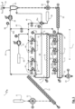
- the Figure 1 shows a schematic representation of an apparatus 1 according to the invention for carrying out the method according to the invention for decomposing, in particular, moist fuels by thermal decomposition by means of partial oxidation.
- the method is of course also applicable to dry fuels, but has particular advantages in the decomposition of relatively moist fuels.
- the apparatus 1 here has a first reactor 3 and a second reactor 5 connected downstream of the first reactor 3.
- the first reactor 3 extends from an inlet section 7, where, for example, moist fuel is fed to the reactor 3, along a longitudinal direction L to an outlet section 9, where at least partially decomposed fuel from the first reactor 3 into the second reactor 5.
- the fuel is fed to the reactor 3 via a rotary valve 11 and a conveyor screw 13, so that the fuel forms a fuel bed on a conveyor device 15 in the inlet section 7 of the first reactor 3.
- the conveyor device 15, for example in the form of a conveyor screw located in the first reactor 3, transports the fuel bed in the longitudinal direction L to the outlet section 9.
- the first reactor 3 forms a gas space 16 in which fuel gas is formed during thermal decomposition.
- the second reactor 5 also has a conveying device 17, whereby the conveying direction in the second reactor 5 is opposite to the conveying direction in the first reactor 3.
- the conveying direction in the second reactor 5 can coincide with the conveying direction in the first reactor 3.
- the inlet section 19 of the second reactor 5 is therefore arranged below the outlet section 9 of the first reactor 3.
- the second reactor 5 is here approximately as long as the first reactor 3 and extends parallel to the first reactor 3 below the first reactor 3.
- the second reactor 5 can be longer or, preferably, shorter than the first reactor 3.
- coal is then discharged via a rotary valve 23.
- the two reactors 3, 5 can be surrounded by a common thermal insulation or heat insulation in order to minimize overall heat loss to the outside.
- the fuel gas produced in the second (lower) reactor 5 can flow upwards, opposite to the fuel bed, from the inlet section 19 of the second reactor 5 into the gas space 16 in the outlet section 9 of the first reactor 3.
- the gas space in the second (lower) reactor 5 can be designed correspondingly smaller than the gas space 16 in the first (upper) reactor 3.
- the device 1 comprises a recirculation system 25 (the lines of which are Fig. 1 shown in dashed lines), with which fuel gas is extracted from the gas space 16 of the first reactor 3 at an extraction point 27.
- the extraction point 27 is located in the illustrated embodiment in the inlet section 7 of the first reactor 3.
- the recirculation system 25 has a recirculation fan 29, with which the flow in the recirculation system 25 is controlled.
- the recirculation system 25 further has a dedusting device 31 in the form of a separator. A portion of the dedusted fuel gas is used for a Fig. 2 shown fuel gas chamber 33.
- Oxidizing agent in the form of air is fed into another part of the dedusted fuel gas at an ignition point 35a of the recirculation system 25, whereby a part of the fuel gas is automatically ignited, and then fed back to the gas space 16 of the first reactor 3 at a feed point 37.
- the feed point 37 is located here in the outlet section 9 of the first reactor 3. This results in a fuel gas flow in the gas space 16 opposite to the conveying direction of the fuel bed.
- a further ignition point 35b is provided here upstream of the dedusting device 31, where oxidizing agent is fed into the recirculation system 25 under the control of a valve 45 in order to prevent the temperature of the extracted fuel gas in the recirculation system 25 from falling below the autoignition temperature of the fuel gas.
- This can be checked using a temperature sensor 38 located downstream of the ignition point 35b, and the valve 45 can be controlled depending on the temperature measurement of the temperature sensor 38. Only as little oxidant as possible should be fed in, but as much as necessary to maintain the temperature.
- the recirculated fuel gas has a temperature above the autoignition temperature of the fuel gas at the respective ignition point 35a,b, it ignites itself upon feeding in the oxidizer.
- the temperature can be controlled by a 25 downstream of the respective ignition point 35a,b.
- the recirculation of the fuel gas thus obtains the vaporization enthalpy required for the relatively high water content in the fuel from the fuel gas.
- a starting aid 39 in the form of a controlled, ignitable liquid gas supply is provided to supply a combustible gas to the ignition point 35a of the recirculation system 25 and ignite it to the first reactor 3 at the supply point.
- the recirculation process is maintained solely by the respective feed of the oxidizing agent to the ignition points 35a,b, so that the starting aid 39 is no longer required.
- the air used as the oxidizing agent is extracted from the ambient air 43 by means of a primary air blower 41 and fed to the recirculation system 25 at the ignition points 35a, b via controllable valves 45. Furthermore, the primary air blower 41 supplies a plurality of nozzles 47 distributed along the length of the two reactors 3, 5, which are designed to introduce oxidizing agent from above into the respective reactor 3, 5.
- the nozzles 47 are each valve-controlled, with the mass flow of oxidizing agent through the respective nozzle 47 being regulated by an associated temperature-controlled valve 49 as a function of a temperature measured in the region of the respective nozzle 47 by an associated temperature sensor 51.
- the dust separated in the dedusting device 31 is fed to the inlet section 19 of the second (lower) reactor 5 via a rotary valve 53 and a conveyor screw 55 so that the separated dust can be completely carbonized in the second reactor 5.
- the reactors 3, 5 and the recirculation system 25 are fed with the fuel gas produced from the fuel, i.e., primarily gaseous hydrocarbons and water vapor, and the oxidant.
- the reactors 3, 5 and the recirculation system 25 should, if possible, have a pressure slightly below the ambient air pressure to prevent gas from escaping, for example, at the rotary valves 11, 23. To achieve this, a portion of the fuel gas is diverted from the recirculation system 25. This portion is slightly larger than the sum of the fuel gas currently produced in the reactors 3, 5 and the supplied oxidant, creating a slight negative pressure.
- Fig. 2 It is shown how the branched-off part of the fuel gas is fed into the fuel gas chamber 33, where ambient air 43 is fed into the fuel gas chamber 33 by means of a secondary air blower 57 for the most complete combustion of the fuel gas.
- a waste heat boiler 59 the heat generated in the fuel gas chamber 33, which is discharged with the exhaust gas 61 of the fuel gas chamber 33, is used for other purposes by means of a useful heat extraction 63.
- a speed-controlled exhaust fan 65 determines the mass flow of exhaust gas 61 from the device 1. The speed of the exhaust fan 65 is preferably dependent on a 3, 5 and/or in the recirculation system 25 by at least one pressure sensor 67.
- the exhaust fan 65 thus ensures the desired slight negative pressure in the reactors 3, 5 and the recirculation system 25.
- at least one pressure sensor 67 is arranged at the outlet section 9 of the first reactor 3 in order to regulate the speed of the exhaust fan 65 according to the pressure measured there.
- a portion of the exhaust gas is fed back to the combustion gas chamber 33 via an exhaust gas recirculation fan 69 to reduce nitrogen oxide emissions.
Landscapes
- Chemical & Material Sciences (AREA)
- Engineering & Computer Science (AREA)
- Oil, Petroleum & Natural Gas (AREA)
- Organic Chemistry (AREA)
- Combustion & Propulsion (AREA)
- Materials Engineering (AREA)
- Chemical Kinetics & Catalysis (AREA)
- General Chemical & Material Sciences (AREA)
- Industrial Gases (AREA)
Priority Applications (2)
| Application Number | Priority Date | Filing Date | Title |
|---|---|---|---|
| EP23214247.1A EP4567090A1 (fr) | 2023-12-05 | 2023-12-05 | Procédé et dispositif pour la décomposition de combustibles par décomposition thermique par oxydation partielle |
| PCT/EP2024/081271 WO2025119567A1 (fr) | 2023-12-05 | 2024-11-06 | Procédé et appareil de clivage de combustibles par décomposition thermique au moyen d'une oxydation partielle |
Applications Claiming Priority (1)
| Application Number | Priority Date | Filing Date | Title |
|---|---|---|---|
| EP23214247.1A EP4567090A1 (fr) | 2023-12-05 | 2023-12-05 | Procédé et dispositif pour la décomposition de combustibles par décomposition thermique par oxydation partielle |
Publications (1)
| Publication Number | Publication Date |
|---|---|
| EP4567090A1 true EP4567090A1 (fr) | 2025-06-11 |
Family
ID=89119263
Family Applications (1)
| Application Number | Title | Priority Date | Filing Date |
|---|---|---|---|
| EP23214247.1A Pending EP4567090A1 (fr) | 2023-12-05 | 2023-12-05 | Procédé et dispositif pour la décomposition de combustibles par décomposition thermique par oxydation partielle |
Country Status (2)
| Country | Link |
|---|---|
| EP (1) | EP4567090A1 (fr) |
| WO (1) | WO2025119567A1 (fr) |
Citations (7)
| Publication number | Priority date | Publication date | Assignee | Title |
|---|---|---|---|---|
| EP0257019A2 (fr) * | 1986-08-14 | 1988-02-24 | VOEST-ALPINE Aktiengesellschaft | Réacteur de gazéification pour la fabrication de gaz combustibles à partir de déchets |
| DE19807988B4 (de) | 1998-02-26 | 2007-11-08 | Wolf, Bodo, Dr.-Ing. | Verfahren zur Abtrennung von flüchtigen Bestandteilen aus festen Brennstoffen |
| US20090250378A1 (en) * | 2008-04-07 | 2009-10-08 | Chun-Yao Wu | Continuous steam pyrolysis method |
| US20120238645A1 (en) * | 2009-11-20 | 2012-09-20 | Ruedlinger Mikael | Thermal and chemical utilization of carbonaceous materials, in particular for emission-free generation of energy |
| DE102007012452B4 (de) | 2007-03-15 | 2014-01-16 | SynCraft Enegineering GmbH | Vergaser |
| EP3858952A1 (fr) | 2020-01-31 | 2021-08-04 | Garden's Best GmbH | Procédé et dispositif de décomposition de combustibles solides par décomposition thermique au moyen de l'oxydation partielle |
| US11613705B2 (en) * | 2012-02-06 | 2023-03-28 | Mcgolden, Llc | Method and system for gasification of biomass |
-
2023
- 2023-12-05 EP EP23214247.1A patent/EP4567090A1/fr active Pending
-
2024
- 2024-11-06 WO PCT/EP2024/081271 patent/WO2025119567A1/fr active Pending
Patent Citations (7)
| Publication number | Priority date | Publication date | Assignee | Title |
|---|---|---|---|---|
| EP0257019A2 (fr) * | 1986-08-14 | 1988-02-24 | VOEST-ALPINE Aktiengesellschaft | Réacteur de gazéification pour la fabrication de gaz combustibles à partir de déchets |
| DE19807988B4 (de) | 1998-02-26 | 2007-11-08 | Wolf, Bodo, Dr.-Ing. | Verfahren zur Abtrennung von flüchtigen Bestandteilen aus festen Brennstoffen |
| DE102007012452B4 (de) | 2007-03-15 | 2014-01-16 | SynCraft Enegineering GmbH | Vergaser |
| US20090250378A1 (en) * | 2008-04-07 | 2009-10-08 | Chun-Yao Wu | Continuous steam pyrolysis method |
| US20120238645A1 (en) * | 2009-11-20 | 2012-09-20 | Ruedlinger Mikael | Thermal and chemical utilization of carbonaceous materials, in particular for emission-free generation of energy |
| US11613705B2 (en) * | 2012-02-06 | 2023-03-28 | Mcgolden, Llc | Method and system for gasification of biomass |
| EP3858952A1 (fr) | 2020-01-31 | 2021-08-04 | Garden's Best GmbH | Procédé et dispositif de décomposition de combustibles solides par décomposition thermique au moyen de l'oxydation partielle |
Also Published As
| Publication number | Publication date |
|---|---|
| WO2025119567A1 (fr) | 2025-06-12 |
Similar Documents
| Publication | Publication Date | Title |
|---|---|---|
| EP1192234B1 (fr) | Procede et dispositif de pyrolyse et de gazeification de substances organiques ou de melanges de substances organiques | |
| DE19945771C1 (de) | Verfahren zur Vergasung von organischen Stoffen und Stoffgemischen | |
| DE102010033646B4 (de) | Verfahren und Schachtvergaser zur Erzeugung von Brenngas aus einem festen Brennstoff | |
| DE102004024672B4 (de) | Vorrichtung und Verfahren zur Erzeugung eines teerfreien Schwachgases durch Vergasung von Biomasse | |
| WO2012007574A1 (fr) | Dispositif et procédé de séchage et de torréfaction d'au moins un flux de matière carboné dans un four à étages | |
| DE102009052902A1 (de) | Niedertemperaturpyrolyse von Biomasse in der Wirbelschicht für eine nachfolgende Flugstromvergasung | |
| EP0846917A2 (fr) | Procédé et appareil pour la production de gaz utilisable à partir de déchets | |
| AT519471B1 (de) | Verkohlungsanlage | |
| WO2011134961A2 (fr) | Procédé et dispositif pour la gazéification de la biomasse | |
| DE202010013745U1 (de) | Schachtvergaser zur Erzeugung von Brenngas aus einem festen Brennstoff | |
| EP3858952A1 (fr) | Procédé et dispositif de décomposition de combustibles solides par décomposition thermique au moyen de l'oxydation partielle | |
| DD202176A5 (de) | Verfahren und einrichtung zur kontinuierlichen erzeugung von brenngas aus organischen abfallstoffen | |
| EP2808377B1 (fr) | Installation et procédé de gazéification de combustibles en morceaux | |
| EP4567090A1 (fr) | Procédé et dispositif pour la décomposition de combustibles par décomposition thermique par oxydation partielle | |
| EP0482306A2 (fr) | Procédé et dispositif pour la combustion des copeaux de bois en produisant des fumées pauvres en substances nocives et à puissance de combustion continûment réglable | |
| DE69002446T2 (de) | Vorrichtung zum Vergasen fester Brennstoffe. | |
| EP1167492A2 (fr) | Procédé et installation pour la production d' un gaz combustible à partir de biomasse | |
| EP1918015A1 (fr) | Equilibrage des gaz de fumées dans des installations de combustion de déchets | |
| EP2787280A1 (fr) | Procédé et dispositif de combustion de combustibles solides pouvant s'écouler | |
| DE102023003286B4 (de) | Verfahren zur Pyrolyse organischer Stoffe und Stoffgemische in einem als Drehrohrofen ausgeführten Pyrolysereaktor durch Kontakt mit einem heißen Gas | |
| EP4410930A1 (fr) | Procédés et dispositifs de production d'un gaz de synthèse contenant de l'hydrogène | |
| EP0750731B1 (fr) | Procede de destruction, en particulier de combustion complete | |
| EP3875564B1 (fr) | Dispositif de génération de gaz pyrolytique permettant de générer du gaz de synthèse à partir d'une matière de départ carbonisable | |
| DE4317413C2 (de) | Verfahren zum Behandeln von kohlenstoffhaltigem Material | |
| EP1915326B1 (fr) | Procede et dispositif pour eliminer des composants organiques volatils contenus dans des gaz brules d'une installation de clinker |
Legal Events
| Date | Code | Title | Description |
|---|---|---|---|
| PUAI | Public reference made under article 153(3) epc to a published international application that has entered the european phase |
Free format text: ORIGINAL CODE: 0009012 |
|
| STAA | Information on the status of an ep patent application or granted ep patent |
Free format text: STATUS: THE APPLICATION HAS BEEN PUBLISHED |
|
| AK | Designated contracting states |
Kind code of ref document: A1 Designated state(s): AL AT BE BG CH CY CZ DE DK EE ES FI FR GB GR HR HU IE IS IT LI LT LU LV MC ME MK MT NL NO PL PT RO RS SE SI SK SM TR |
|
| STAA | Information on the status of an ep patent application or granted ep patent |
Free format text: STATUS: THE APPLICATION IS DEEMED TO BE WITHDRAWN |