EP4567248A2 - Connecteur de profil - Google Patents
Connecteur de profil Download PDFInfo
- Publication number
- EP4567248A2 EP4567248A2 EP25171877.1A EP25171877A EP4567248A2 EP 4567248 A2 EP4567248 A2 EP 4567248A2 EP 25171877 A EP25171877 A EP 25171877A EP 4567248 A2 EP4567248 A2 EP 4567248A2
- Authority
- EP
- European Patent Office
- Prior art keywords
- profile strip
- profile
- frame
- free
- strip
- Prior art date
- Legal status (The legal status is an assumption and is not a legal conclusion. Google has not performed a legal analysis and makes no representation as to the accuracy of the status listed.)
- Pending
Links
Images
Classifications
-
- E—FIXED CONSTRUCTIONS
- E06—DOORS, WINDOWS, SHUTTERS, OR ROLLER BLINDS IN GENERAL; LADDERS
- E06B—FIXED OR MOVABLE CLOSURES FOR OPENINGS IN BUILDINGS, VEHICLES, FENCES OR LIKE ENCLOSURES IN GENERAL, e.g. DOORS, WINDOWS, BLINDS, GATES
- E06B9/00—Screening or protective devices for wall or similar openings, with or without operating or securing mechanisms; Closures of similar construction
- E06B9/52—Devices affording protection against insects, e.g. fly screens; Mesh windows for other purposes
- E06B9/522—Dimensionally adjustable fly screens
-
- E—FIXED CONSTRUCTIONS
- E06—DOORS, WINDOWS, SHUTTERS, OR ROLLER BLINDS IN GENERAL; LADDERS
- E06B—FIXED OR MOVABLE CLOSURES FOR OPENINGS IN BUILDINGS, VEHICLES, FENCES OR LIKE ENCLOSURES IN GENERAL, e.g. DOORS, WINDOWS, BLINDS, GATES
- E06B3/00—Window sashes, door leaves, or like elements for closing wall or like openings; Layout of fixed or moving closures, e.g. windows in wall or like openings; Features of rigidly-mounted outer frames relating to the mounting of wing frames
- E06B3/96—Corner joints or edge joints for windows, doors, or the like frames or wings
- E06B3/964—Corner joints or edge joints for windows, doors, or the like frames or wings using separate connection pieces, e.g. T-connection pieces
- E06B3/9641—Corner joints or edge joints for windows, doors, or the like frames or wings using separate connection pieces, e.g. T-connection pieces part of which remains visible
-
- E—FIXED CONSTRUCTIONS
- E06—DOORS, WINDOWS, SHUTTERS, OR ROLLER BLINDS IN GENERAL; LADDERS
- E06B—FIXED OR MOVABLE CLOSURES FOR OPENINGS IN BUILDINGS, VEHICLES, FENCES OR LIKE ENCLOSURES IN GENERAL, e.g. DOORS, WINDOWS, BLINDS, GATES
- E06B3/00—Window sashes, door leaves, or like elements for closing wall or like openings; Layout of fixed or moving closures, e.g. windows in wall or like openings; Features of rigidly-mounted outer frames relating to the mounting of wing frames
- E06B3/96—Corner joints or edge joints for windows, doors, or the like frames or wings
- E06B3/964—Corner joints or edge joints for windows, doors, or the like frames or wings using separate connection pieces, e.g. T-connection pieces
- E06B3/9642—Butt type joints with at least one frame member cut off square; T-shape joints
-
- E—FIXED CONSTRUCTIONS
- E06—DOORS, WINDOWS, SHUTTERS, OR ROLLER BLINDS IN GENERAL; LADDERS
- E06B—FIXED OR MOVABLE CLOSURES FOR OPENINGS IN BUILDINGS, VEHICLES, FENCES OR LIKE ENCLOSURES IN GENERAL, e.g. DOORS, WINDOWS, BLINDS, GATES
- E06B3/00—Window sashes, door leaves, or like elements for closing wall or like openings; Layout of fixed or moving closures, e.g. windows in wall or like openings; Features of rigidly-mounted outer frames relating to the mounting of wing frames
- E06B3/96—Corner joints or edge joints for windows, doors, or the like frames or wings
- E06B3/964—Corner joints or edge joints for windows, doors, or the like frames or wings using separate connection pieces, e.g. T-connection pieces
- E06B3/9644—L-shaped corner pieces having two articulated or flexible joined legs; Corner joints with variable angle
-
- E—FIXED CONSTRUCTIONS
- E06—DOORS, WINDOWS, SHUTTERS, OR ROLLER BLINDS IN GENERAL; LADDERS
- E06B—FIXED OR MOVABLE CLOSURES FOR OPENINGS IN BUILDINGS, VEHICLES, FENCES OR LIKE ENCLOSURES IN GENERAL, e.g. DOORS, WINDOWS, BLINDS, GATES
- E06B3/00—Window sashes, door leaves, or like elements for closing wall or like openings; Layout of fixed or moving closures, e.g. windows in wall or like openings; Features of rigidly-mounted outer frames relating to the mounting of wing frames
- E06B3/96—Corner joints or edge joints for windows, doors, or the like frames or wings
- E06B3/964—Corner joints or edge joints for windows, doors, or the like frames or wings using separate connection pieces, e.g. T-connection pieces
- E06B3/968—Corner joints or edge joints for windows, doors, or the like frames or wings using separate connection pieces, e.g. T-connection pieces characterised by the way the connecting pieces are fixed in or on the frame members
- E06B3/9681—Corner joints or edge joints for windows, doors, or the like frames or wings using separate connection pieces, e.g. T-connection pieces characterised by the way the connecting pieces are fixed in or on the frame members by press fit or adhesion
Definitions
- the present invention relates to a kit for a frame, and in particular to a kit for a frame of an (insect) protection device, as well as a profile connector.
- An (insect, pollen, and/or sun) protection grille is typically attached to such a frame of a protection device, spanning the opening defined by the frame.
- the protection device can then be mounted on a frame (in particular a window or door frame) of a building opening (in particular a window or door).
- kits for a frame of an insect screen comprising four frame assemblies, each frame assembly having an inner profile strip and an outer profile strip, which are connected to one another via a corner connector comprising a pivot axis.
- the inner profile strips and the outer profile strips of the four frame assemblies are each aligned parallel to one another.
- the end user must unfold the frame assemblies thus delivered around the pivot axis of the corner connector so that the inner profile strip and the outer profile strip are arranged at a 90° angle to one another.
- the end user then has to align the profile strips of the frame groups and slide them together to form the frame, with the inner profile strip of one frame assembly being telescopic to the outer profile strip of an adjacent frame assembly.
- a frame consisting of four frame assemblies is also US 4,279,288 A Although such kits significantly simplify assembly for the end user, the presence of four frame assemblies requires the assembly of a large number of frame assemblies.
- EP 3 835 539 A1 also a kit consisting of exactly two frame assemblies, each of which can be positioned at a right angle for assembly.
- these frame assemblies feature a plug-in connection at the free ends near the corner connectors. Therefore, different corner connector components are required at the free ends of these frame assemblies than those required to form a pivot joint within a frame assembly. Therefore, providing such a kit with exactly two frame assemblies requires a larger number of different components.
- EP 3 690 177 A1 and EP 3 910 155 A1 A solution is known for how a hinged corner connector can be protected from accidental folding back in its opened position.
- EP 3 690 177 A1 a separate fixing element which can be inserted into both connecting legs of a corner connector in the unfolded assembly position.
- EP 3 910 155 A1 suggests that the corner connector have a clamp design onto which a mounting device can be clipped.
- the frame There is also a desire for the frame to be more reliably secured against folding back. Furthermore, it is desirable for the frame to be highly stable.
- the object of the present invention is therefore to eliminate the disadvantages described with reference to the prior art and, in particular, to provide a profile connector with which the frame has greater stability.
- the disclosure particularly relates to a kit for a frame, and in particular to a kit for a frame of an insect screen, and preferably for a frame of an insect screen door.
- the kit comprises a first pre-assembled frame assembly and a second pre-assembled frame assembly. Furthermore, the kit comprises at least one first connecting profile strip and at least one second connecting profile strip.
- Each of the two frame assemblies comprises a first free profile strip, a second free profile strip and a connecting device which has at least one further profile strip.
- the first free profile strip is connected to the connecting device at a first end of the connecting device via a first pivot joint having a pivot axis.
- the second free profile strip is connected to the connecting device at a second end of the connecting device via a second pivot joint having a pivot axis.
- the two pivot joints of each frame assembly are designed such that in an initial position the two free profile strips and the connecting device are aligned parallel to one another and that the free profile strips can be pivoted relative to the connecting device by the respective axis of rotation can be transferred into an assembly position in which the frame assembly is U-shaped.
- the first free profile strip of the first frame assembly, on the one hand, and the first free profile strip of the second frame assembly, on the other hand can be telescopically connected to the at least one first connecting profile strip.
- the second free profile strip of the first frame assembly, on the one hand, and the second free profile strip of the second frame assembly, on the other hand can be telescopically connected to the at least one second connecting profile strip.
- the end user is provided with two modules containing pre-assembled frame assemblies, which the end user can bring into a U-shaped position by unfolding the free profile strips.
- the two U-shaped modules are connected to one another by connecting profile strips, for which purpose the first free profile strips of the frame assemblies are inserted in a telescopic manner into or onto the at least one first connecting profile strip, while the second free profile strips of the frame assemblies are inserted in a telescopic manner into or onto the at least one second connecting profile strip.
- the frame it is thus possible for the frame to have a greater height than the sum of the corresponding free profile strips of different frame assemblies, and the height can also be adapted to a building opening due to the telescoping nature of the modules.
- the essentially parallel alignment of the free profile strip in the initial position to the connecting device also ensures that the kit can be provided to the end customer in a compact form in a container (packaging). While the free profile strips in the assembly position are essentially arranged in a plane defined jointly with the connecting device, it is entirely possible that in the initial position the free profile strips are offset from one another orthogonally to the plane and directly adjacent to one another, which is still considered parallel.
- the at least one first connecting profile strip and the at least one second connecting profile strip can each comprise at least one inner profile strip and at least one outer profile strip, so that the at least one first inner profile strip and the at least one first outer profile strip can be arranged telescopically relative to one another. This may potentially allow an even greater frame height to be achieved, with the connecting profile strips having a comparatively short length in the state provided to the end customer.
- the kit comprises exactly one first connecting profile strip and exactly one second connecting profile strip, wherein in the assembled position both the first free profile strip of the first frame assembly and the first free profile strip of the second frame assembly can be telescopically inserted into or onto the first connecting profile strip from opposite sides, wherein the second free profile strip of the first frame assembly and the second free profile strip of the second frame assembly can be inserted into or onto the second connecting profile strip from opposite sides.
- the number of components provided to the end customer is thus low, which also reduces the assembly effort.
- the free profile strips of the frame assemblies are designed as inner profile strips and the connecting profile strips as outer profile strips. In this Configuration makes it easier for the end customer to attach additional components to the connecting profile strips of the frame produced by the kit.
- the kit can comprise a central connecting device with which two connecting profile strips arranged parallel to one another in the assembled state can be connected.
- a central connecting device can be implemented, for example, by at least one profile strip which is attached on the one hand to a connecting profile strip of the at least one first connecting profile strip and on the other hand to a profile strip of the at least one second connecting profile strip.
- the central connecting device can be screwed to the two connecting profile strips.
- the central connecting device it is also possible for the central connecting device to be attached to the connecting profile strips by other positive and/or non-positive connections.
- the central connecting device can comprise at least one inner profile strip and at least one outer profile strip, which can be telescopically moved into one another. By telescopically moving them relative to one another, the length of the central connecting device and thus the width of the frame can be adjusted.
- the central connecting device comprises exactly two inner profile strips, each of which can be attached to a connecting profile strip, and exactly one outer profile strip, into which the two inner profile strips can be inserted from opposite sides.
- At least one axis of rotation of the swivel joint is in the plane spanned by the frame and approximately at a 45° angle to the direction of extension of the free profile strip is aligned.
- the axes of rotation of the pivot joints of both frame assemblies are aligned parallel to one another (when the frame is assembled) and orthogonal to a plane spanned by the frame.
- the free profile strips are arranged in the plane defined by the free profile strips and the connecting device in the assembly position, even during transfer from the starting position to the assembly position. In the latter embodiment, a particularly stable connection of the free profile strips to the connecting device in the assembly position is possible.
- the (free) profile strips are designed as inner profile strips or outer profile strips.
- all free profile strips of the frame assemblies can be designed as inner profile strips that can be inserted into outer profile strips of the connecting profile strips.
- the two frame assemblies have outer profile strips as free profile strips that can be pushed onto inner profile strips of the connecting profile strips.
- the (mutually assigned) profile strips can be designed as nestable tubes (with a circular or rectangular cross-section).
- the profile strips have at least one contour extending along their longitudinal extent, which, for example, enables the attachment of a seal and/or a protective grille.
- a groove extending in the direction of the longitudinal extent of the profile strip can be provided for receiving a (brush) seal.
- a contour projection or contour recess can be provided, which extends along the longitudinal extent of the profile strip, to which an (insect) protective grille can be attached, if necessary by means of additional components (such as a fixing strip).
- the outer contour of an inner profile strip is matched to the inner contour of the associated outer profile strip so that they can be telescopically pushed into one another.
- the free profile strips of the frame assembly are arranged substantially parallel but offset to one another and to the connecting device in the initial position.
- the free profile strips of a frame assembly can be offset from one another orthogonally to the plane and arranged on the same side of the connecting device.
- the free profile strips are arranged in one plane in the assembly position, they can be arranged directly next to one another (orthogonally to the plane) in the initial position by means of slight bracing.
- the connecting device it is possible for the connecting device to be fixed in length.
- the frame could only be adjustable in size (height) in the direction of the longitudinal extension of the connecting profile strip.
- the connecting device of a frame assembly comprises at least one inner profile strip and at least one outer profile strip arranged telescopically relative to the at least one inner profile strip.
- the frame is adjustable in size in its plane in two mutually orthogonal directions.
- the swivel joint having the rotation axis it is possible for the swivel joint having the rotation axis to be formed in one piece with a profile strip.
- the swivel joint be formed by an independent component, namely a profile connector.
- the first free profile strip and the second free profile strip are each connected to the connecting device via a profile connector forming the swivel joint.
- a first connecting leg of a profile connector is formed into a free profile strip and a second connecting leg, which can be pivoted about the rotation axis relative to the first connecting leg,
- the connecting leg of the profile connector is inserted into a profile strip of the connecting device.
- the two frame assemblies are each secured in their assembled position by a fixing device.
- the frame assemblies can have locking mechanisms in the area of the swivel joint that interlock in the assembled position, thus preventing accidental pivoting back.
- the fixing can be realized by a separate fixing element that secures the swivel joint in its unfolded position against unintentional pivoting back.
- the kit include a package (e.g., a box) in which the two frame assemblies are arranged in their initial position and the connecting profile strips.
- a package e.g., a box
- other components of the kit such as fixing elements, suspension elements, the central connecting device, and/or insect screens, can be arranged in the package.
- the above-described object is achieved in particular by a profile connector for a frame and in particular for a frame assembly of the previously described kit.
- the profile connector comprises at least one first connecting leg, which can be inserted into a profile strip, and a second connecting leg, which can be inserted into a profile strip.
- the profile connector also comprises a pivot joint having at least one pivot axis between the first connecting leg and the second connecting leg, which pivot joint is designed such that the first The first connecting leg and the second connecting leg can be transferred from an initial position by a relative pivoting movement about the at least one axis of rotation into an assembly position in which the first connecting leg and the second connecting leg are arranged in a plane at a right angle to one another.
- the profile connector comprise a screw and that the first connecting leg has a receptacle (for example a simple hole or a threaded bore) for the screw, wherein the receptacle is arranged such that the screw can be screwed through the second connecting leg into the receptacle in the assembled position.
- the second connecting leg has a type of hole through which the screw projects and against whose edge the screw head comes into contact. The screw can thus be used to clamp the first connecting leg to the second connecting leg, so that due to the relative pivoting mobility, any play existing between the connecting legs can be minimized or completely eliminated even in the assembled position, which in turn gives the frame greater stability.
- the screw receptacle is designed as a simple hole into which the screw can be screwed.
- the connecting legs are made of metal, it would be advisable to design the receptacle as a threaded hole.
- the profile connector comprises, in particular, a connecting leg that can be at least partially inserted into a previously described profile strip, in particular in a force-fitting manner.
- the outer profile of the section of the connecting leg that can be inserted into the profile strip is thus adapted to the inner profile of the corresponding profile strip.
- the profile connector has at least one axis of rotation for forming the pivot joint. If the movement of the connecting legs from the initial position to the assembly position occurs in the plane defined by the assembly position, preferably exactly one axis of rotation is formed.
- the profile connector has exactly two connecting legs that can be brought into a right angle to one another, it is also referred to as a corner connector. However, it can also be provided that the profile connector has three connecting legs, in which case each connecting leg is arranged at a right angle to at least one other connecting leg in the assembled position.
- a profile connector can be used, for example, to form a frame for an insect screen door.
- a receptacle for a screw can be formed in each of two connecting legs, whereby the screw can be screwed through the other (third) connecting leg into the receptacle.
- the swivel joint and the connecting legs are designed in particular such that the connecting legs are arranged parallel to each other in the starting position.
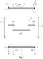
- the kit 3 for a frame shown comprises a first frame assembly 1, a second frame assembly 2, a first connecting profile strip 7.1, a second connecting profile strip 7.2 and a central connecting device 10.
- the first frame assembly 1 comprises a first free profile strip 1.1, a second free profile strip 1.2 and a connecting device 1.3 formed from two profile strips 1.3a and 1.3b (see in particular also Figure 2 and 3 ).
- the second frame assembly 2 comprises a first free profile strip 2.1, a second free profile strip 2.2 and a connecting device 2.3 formed from two profile strips 2.3a and 2.3b (see also Figure 2 and 3 ).
- the free profile strips 1.1, 1.2, 2.1 and 2.2 of the frame assemblies 1 and 2 are each connected via a profile connector 5 to the associated connecting device 1.3 or 2.3.
- Such a profile connector is described with reference to the Figures 4 and 5 explained below.
- the first free profile strips 1.1 and 2.1 are each connected to the connecting device 1.3, 2.3 via a first pivot joint 4.1 having a pivot axis 4.1a (see also Figure 4 with respect to the rotation axis 4.1a).
- the second free profile strips 1.2 and 2.2 are each connected to the connecting device 1.3, 2.3 via a second pivot joint 4.2 having a rotation axis 4.2a.
- the first connecting profile strip 7.1 and the second connecting profile strip 7.2 are each designed as an external profile strip.
- the central connecting device 10 comprises two outer profile strips 10.1 and 10.2 and an inner profile strip 10.3, which can be telescopically inserted into the two outer profile strips 10.1 and 10.2.
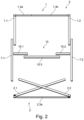
- FIG 2 is the kit 3 of the Figure 1 shown, with the frame assembly 1 in an assembly position and the frame assembly 2 in an intermediate position between the initial position and the assembly position.
- the free profile strips 2.1 and 2.2 of the second frame assembly 2 are thus already pivoted by a few degrees from their initial position.
- the free profile strips 1.1 and 1.2 are each arranged at a right angle to the connecting device 1.3.
- the connecting device 1.3 consists of two profile strips 1.3a and 1.3b, which can be telescoped towards each other to adjust the width of the subsequent frame.
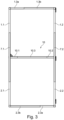
- the first free profile strip 1.1 of the first frame assembly 1 and the first free profile strip 2.1 of the second frame assembly 2 are inserted from opposite sides into the first connecting profile strip 7.1, while the second free profile strip 1.2 of the first frame assembly 1 and the second free profile strip 2.2 of the second frame assembly 2 are inserted into the second connecting profile strip 7.2 are inserted from opposite sides.
- the height of the frame can thus be adjusted by sliding the frame assemblies 1 and 2 along the longitudinal extent of the connecting profile strips 7.1 and 7.2.
- the two connecting profile strips 7.1 and 7.2 are connected to each other via the central connecting device 10, so that the frame has a high level of stability.
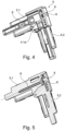
- a profile connector 5 designed as a corner connector is shown, which is also used in the frame assemblies of the Figures 1 to 3 can be used.
- the profile connector 5 has a first connecting leg 5.1 and a second connecting leg 5.2, each of which can be inserted in sections into a profile strip.
- a pivot axis 4.1a is formed between the first connecting leg 5.1 and the second connecting leg 5.2, so that the connecting legs 5.1, 5.2 can be pivoted from an initial position, in which the connecting legs 5.1, 5.2 or the profile strips are aligned approximately parallel to one another, into an assembly position in which the connecting legs 5.1, 5.2 or the profile strips are arranged at a right angle to one another.
- Figure 4 the connecting legs 5.1 and 5.2 are in the assembly position.
- a receptacle 8 is formed in the first connecting leg 5.1, while a through hole 9 is formed in the second connecting leg 5.2.
- the receptacle 8 and the through-hole 9 are designed on the connecting legs 5.1 and 5.2 in such a way that a screw 6 can be screwed through the through-hole 9 into the receptacle 8 in the assembly position of the profile connector.
- the screw 6 clamps the first connecting leg 5.1 against the second connecting leg 5.2 and thus also holds it in the assembly position.
- the screw 6 can therefore also any play between the connecting legs 5.1 and 5.2 is eliminated, thereby further increasing the stability of the frame.
Landscapes
- Engineering & Computer Science (AREA)
- Structural Engineering (AREA)
- Civil Engineering (AREA)
- Life Sciences & Earth Sciences (AREA)
- Insects & Arthropods (AREA)
- Pest Control & Pesticides (AREA)
- Architecture (AREA)
- Mutual Connection Of Rods And Tubes (AREA)
Priority Applications (1)
| Application Number | Priority Date | Filing Date | Title |
|---|---|---|---|
| EP25171877.1A EP4567248A3 (fr) | 2023-04-12 | 2023-04-12 | Connecteur de profil |
Applications Claiming Priority (2)
| Application Number | Priority Date | Filing Date | Title |
|---|---|---|---|
| EP25171877.1A EP4567248A3 (fr) | 2023-04-12 | 2023-04-12 | Connecteur de profil |
| EP23167568.7A EP4446558B1 (fr) | 2023-04-12 | 2023-04-12 | Kit de construction pour un cadre |
Related Parent Applications (1)
| Application Number | Title | Priority Date | Filing Date |
|---|---|---|---|
| EP23167568.7A Division EP4446558B1 (fr) | 2023-04-12 | 2023-04-12 | Kit de construction pour un cadre |
Publications (2)
| Publication Number | Publication Date |
|---|---|
| EP4567248A2 true EP4567248A2 (fr) | 2025-06-11 |
| EP4567248A3 EP4567248A3 (fr) | 2025-08-20 |
Family
ID=86006665
Family Applications (2)
| Application Number | Title | Priority Date | Filing Date |
|---|---|---|---|
| EP23167568.7A Active EP4446558B1 (fr) | 2023-04-12 | 2023-04-12 | Kit de construction pour un cadre |
| EP25171877.1A Pending EP4567248A3 (fr) | 2023-04-12 | 2023-04-12 | Connecteur de profil |
Family Applications Before (1)
| Application Number | Title | Priority Date | Filing Date |
|---|---|---|---|
| EP23167568.7A Active EP4446558B1 (fr) | 2023-04-12 | 2023-04-12 | Kit de construction pour un cadre |
Country Status (1)
| Country | Link |
|---|---|
| EP (2) | EP4446558B1 (fr) |
Citations (4)
| Publication number | Priority date | Publication date | Assignee | Title |
|---|---|---|---|---|
| US4279288A (en) | 1979-05-29 | 1981-07-21 | Lanier George G | Adjustable frame apparatus |
| EP3690177A1 (fr) | 2019-04-25 | 2020-08-05 | Büdenbender, Arnd | Raccord profilé à articulation rotative |
| EP3835539A1 (fr) | 2019-12-13 | 2021-06-16 | Büdenbender, Arnd | Composant pour un cadre |
| EP3910155A1 (fr) | 2020-05-12 | 2021-11-17 | Büdenbender, Arnd | Dispositif de protection |
Family Cites Families (3)
| Publication number | Priority date | Publication date | Assignee | Title |
|---|---|---|---|---|
| US498868A (en) * | 1893-06-06 | Pocket window-screen | ||
| AT394085B (de) * | 1990-07-30 | 1992-01-27 | Austria Metall | Eckwinkel zum einsetzen in hohlprofilleisten fuer rahmen von fenstern, tueren, fassadenteilen u. dgl. |
| DE102010062751A1 (de) * | 2010-12-09 | 2012-06-14 | Greiner Tool.Tec Gmbh | Eckverbindungsvorrichtung für Profile |
-
2023
- 2023-04-12 EP EP23167568.7A patent/EP4446558B1/fr active Active
- 2023-04-12 EP EP25171877.1A patent/EP4567248A3/fr active Pending
Patent Citations (4)
| Publication number | Priority date | Publication date | Assignee | Title |
|---|---|---|---|---|
| US4279288A (en) | 1979-05-29 | 1981-07-21 | Lanier George G | Adjustable frame apparatus |
| EP3690177A1 (fr) | 2019-04-25 | 2020-08-05 | Büdenbender, Arnd | Raccord profilé à articulation rotative |
| EP3835539A1 (fr) | 2019-12-13 | 2021-06-16 | Büdenbender, Arnd | Composant pour un cadre |
| EP3910155A1 (fr) | 2020-05-12 | 2021-11-17 | Büdenbender, Arnd | Dispositif de protection |
Also Published As
| Publication number | Publication date |
|---|---|
| EP4446558C0 (fr) | 2025-04-30 |
| EP4567248A3 (fr) | 2025-08-20 |
| EP4446558B1 (fr) | 2025-04-30 |
| EP4446558A1 (fr) | 2024-10-16 |
Similar Documents
| Publication | Publication Date | Title |
|---|---|---|
| DE9212112U1 (de) | Tafel | |
| EP0789984A1 (fr) | Baie pour armoire de distribution | |
| EP3683397B1 (fr) | Cadre pourvu de raccords de profilé comportant une articulation rotative | |
| EP3690177B1 (fr) | Raccord profilé à articulation rotative | |
| EP3835539B3 (fr) | Kit pour un cadre | |
| EP4202174B1 (fr) | Kit de construction pour cadre | |
| EP4446558B1 (fr) | Kit de construction pour un cadre | |
| DE10142628A1 (de) | Verschluss- und Abdichtelement | |
| EP0205757A1 (fr) | Bloc de fibres pliées | |
| EP3875728B1 (fr) | Module de connecteur de profil et cadre doté d'un module de connecteur de profil | |
| EP3730310B1 (fr) | Cadre à articulations tournantes | |
| DE69525798T2 (de) | Ausrücksystem für eine Heckladeeinrichtung | |
| DE2750503B2 (de) | Vorrichtung zum gegenseitigen Verbinden von Profilstäben | |
| EP3264398A1 (fr) | Dispositif d'enfichage | |
| DE60010832T2 (de) | Tischart welche mit mindestens einem faltbaren Fuss oder Untergestell versehen ist | |
| DE102022124772B3 (de) | Zusammenklappbare Steighilfe mit Gelenkarretierung | |
| DE202019005704U1 (de) | Rahmen einer Schutzvorrichtung | |
| EP3431697A1 (fr) | Dispositif d'ombrage | |
| EP0893557A1 (fr) | Ensemble de mâts de tente et dispositif de blocage correspondant | |
| EP4501173A1 (fr) | Dispositif pour faire pivoter parallèlement une plate-forme d'un meuble et élément de liaison pour un tel dispositif | |
| DE9217635U1 (de) | Zentralstütze eines zusammenlegbaren Schirms | |
| DE202025003560U1 (de) | Spannrahmen für ein Insektenschutzgitter zum Einsetzen in eine Fensteröffnung | |
| DE202020005587U1 (de) | Abstandhalter, Führungsschiene für einen Raffstore oder eine Jalousie sowie Raffstore und Jalousie | |
| DE102023207323A1 (de) | Vorrichtung zum parallelen Ausschwenken einer Plattform aus einem Möbel sowie Verbindungselement für eine solche Vorrichtung | |
| EP4449951A1 (fr) | Châssis avec un mécanisme de serrage et procédé pour relier au moins un profilé en accordéon à l'aide d'un mécanisme de serrage |
Legal Events
| Date | Code | Title | Description |
|---|---|---|---|
| PUAI | Public reference made under article 153(3) epc to a published international application that has entered the european phase |
Free format text: ORIGINAL CODE: 0009012 |
|
| STAA | Information on the status of an ep patent application or granted ep patent |
Free format text: STATUS: THE APPLICATION HAS BEEN PUBLISHED |
|
| AC | Divisional application: reference to earlier application |
Ref document number: 4446558 Country of ref document: EP Kind code of ref document: P |
|
| AK | Designated contracting states |
Kind code of ref document: A2 Designated state(s): AL AT BE BG CH CY CZ DE DK EE ES FI FR GB GR HR HU IE IS IT LI LT LU LV MC ME MK MT NL NO PL PT RO RS SE SI SK SM TR |
|
| REG | Reference to a national code |
Ref country code: DE Ref legal event code: R079 Free format text: PREVIOUS MAIN CLASS: E06B0009520000 Ipc: E06B0003968000 |
|
| PUAL | Search report despatched |
Free format text: ORIGINAL CODE: 0009013 |
|
| AK | Designated contracting states |
Kind code of ref document: A3 Designated state(s): AL AT BE BG CH CY CZ DE DK EE ES FI FR GB GR HR HU IE IS IT LI LT LU LV MC ME MK MT NL NO PL PT RO RS SE SI SK SM TR |
|
| RIC1 | Information provided on ipc code assigned before grant |
Ipc: E06B 3/968 20060101AFI20250715BHEP Ipc: E06B 3/964 20060101ALI20250715BHEP Ipc: E06B 9/52 20060101ALI20250715BHEP |
|
| STAA | Information on the status of an ep patent application or granted ep patent |
Free format text: STATUS: REQUEST FOR EXAMINATION WAS MADE |
|
| 17P | Request for examination filed |
Effective date: 20260213 |