EP4567959A1 - Positivelektrode für festkörperbatterie und festkörperbatterie damit - Google Patents
Positivelektrode für festkörperbatterie und festkörperbatterie damit Download PDFInfo
- Publication number
- EP4567959A1 EP4567959A1 EP24845857.2A EP24845857A EP4567959A1 EP 4567959 A1 EP4567959 A1 EP 4567959A1 EP 24845857 A EP24845857 A EP 24845857A EP 4567959 A1 EP4567959 A1 EP 4567959A1
- Authority
- EP
- European Patent Office
- Prior art keywords
- positive electrode
- porous carbon
- active material
- electrode active
- carbon additive
- Prior art date
- Legal status (The legal status is an assumption and is not a legal conclusion. Google has not performed a legal analysis and makes no representation as to the accuracy of the status listed.)
- Pending
Links
Images
Classifications
-
- H—ELECTRICITY
- H01—ELECTRIC ELEMENTS
- H01M—PROCESSES OR MEANS, e.g. BATTERIES, FOR THE DIRECT CONVERSION OF CHEMICAL ENERGY INTO ELECTRICAL ENERGY
- H01M4/00—Electrodes
- H01M4/02—Electrodes composed of, or comprising, active material
- H01M4/13—Electrodes for accumulators with non-aqueous electrolyte, e.g. for lithium-accumulators; Processes of manufacture thereof
-
- H—ELECTRICITY
- H01—ELECTRIC ELEMENTS
- H01M—PROCESSES OR MEANS, e.g. BATTERIES, FOR THE DIRECT CONVERSION OF CHEMICAL ENERGY INTO ELECTRICAL ENERGY
- H01M10/00—Secondary cells; Manufacture thereof
- H01M10/05—Accumulators with non-aqueous electrolyte
- H01M10/052—Li-accumulators
-
- H—ELECTRICITY
- H01—ELECTRIC ELEMENTS
- H01M—PROCESSES OR MEANS, e.g. BATTERIES, FOR THE DIRECT CONVERSION OF CHEMICAL ENERGY INTO ELECTRICAL ENERGY
- H01M10/00—Secondary cells; Manufacture thereof
- H01M10/05—Accumulators with non-aqueous electrolyte
- H01M10/052—Li-accumulators
- H01M10/0525—Rocking-chair batteries, i.e. batteries with lithium insertion or intercalation in both electrodes; Lithium-ion batteries
-
- H—ELECTRICITY
- H01—ELECTRIC ELEMENTS
- H01M—PROCESSES OR MEANS, e.g. BATTERIES, FOR THE DIRECT CONVERSION OF CHEMICAL ENERGY INTO ELECTRICAL ENERGY
- H01M10/00—Secondary cells; Manufacture thereof
- H01M10/05—Accumulators with non-aqueous electrolyte
- H01M10/056—Accumulators with non-aqueous electrolyte characterised by the materials used as electrolytes, e.g. mixed inorganic/organic electrolytes
- H01M10/0561—Accumulators with non-aqueous electrolyte characterised by the materials used as electrolytes, e.g. mixed inorganic/organic electrolytes the electrolyte being constituted of inorganic materials only
- H01M10/0562—Solid materials
-
- H—ELECTRICITY
- H01—ELECTRIC ELEMENTS
- H01M—PROCESSES OR MEANS, e.g. BATTERIES, FOR THE DIRECT CONVERSION OF CHEMICAL ENERGY INTO ELECTRICAL ENERGY
- H01M10/00—Secondary cells; Manufacture thereof
- H01M10/42—Methods or arrangements for servicing or maintenance of secondary cells or secondary half-cells
- H01M10/4235—Safety or regulating additives or arrangements in electrodes, separators or electrolyte
-
- H—ELECTRICITY
- H01—ELECTRIC ELEMENTS
- H01M—PROCESSES OR MEANS, e.g. BATTERIES, FOR THE DIRECT CONVERSION OF CHEMICAL ENERGY INTO ELECTRICAL ENERGY
- H01M4/00—Electrodes
- H01M4/02—Electrodes composed of, or comprising, active material
- H01M4/04—Processes of manufacture in general
- H01M4/0402—Methods of deposition of the material
- H01M4/0404—Methods of deposition of the material by coating on electrode collectors
-
- H—ELECTRICITY
- H01—ELECTRIC ELEMENTS
- H01M—PROCESSES OR MEANS, e.g. BATTERIES, FOR THE DIRECT CONVERSION OF CHEMICAL ENERGY INTO ELECTRICAL ENERGY
- H01M4/00—Electrodes
- H01M4/02—Electrodes composed of, or comprising, active material
- H01M4/62—Selection of inactive substances as ingredients for active masses, e.g. binders, fillers
-
- H—ELECTRICITY
- H01—ELECTRIC ELEMENTS
- H01M—PROCESSES OR MEANS, e.g. BATTERIES, FOR THE DIRECT CONVERSION OF CHEMICAL ENERGY INTO ELECTRICAL ENERGY
- H01M4/00—Electrodes
- H01M4/02—Electrodes composed of, or comprising, active material
- H01M4/62—Selection of inactive substances as ingredients for active masses, e.g. binders, fillers
- H01M4/621—Binders
- H01M4/622—Binders being polymers
-
- H—ELECTRICITY
- H01—ELECTRIC ELEMENTS
- H01M—PROCESSES OR MEANS, e.g. BATTERIES, FOR THE DIRECT CONVERSION OF CHEMICAL ENERGY INTO ELECTRICAL ENERGY
- H01M4/00—Electrodes
- H01M4/02—Electrodes composed of, or comprising, active material
- H01M4/62—Selection of inactive substances as ingredients for active masses, e.g. binders, fillers
- H01M4/624—Electric conductive fillers
- H01M4/625—Carbon or graphite
-
- H—ELECTRICITY
- H01—ELECTRIC ELEMENTS
- H01G—CAPACITORS; CAPACITORS, RECTIFIERS, DETECTORS, SWITCHING DEVICES, LIGHT-SENSITIVE OR TEMPERATURE-SENSITIVE DEVICES OF THE ELECTROLYTIC TYPE
- H01G11/00—Hybrid capacitors, i.e. capacitors having different positive and negative electrodes; Electric double-layer [EDL] capacitors; Processes for the manufacture thereof or of parts thereof
- H01G11/22—Electrodes
- H01G11/24—Electrodes characterised by structural features of the materials making up or comprised in the electrodes, e.g. form, surface area or porosity; characterised by the structural features of powders or particles used therefor
-
- H—ELECTRICITY
- H01—ELECTRIC ELEMENTS
- H01G—CAPACITORS; CAPACITORS, RECTIFIERS, DETECTORS, SWITCHING DEVICES, LIGHT-SENSITIVE OR TEMPERATURE-SENSITIVE DEVICES OF THE ELECTROLYTIC TYPE
- H01G11/00—Hybrid capacitors, i.e. capacitors having different positive and negative electrodes; Electric double-layer [EDL] capacitors; Processes for the manufacture thereof or of parts thereof
- H01G11/22—Electrodes
- H01G11/30—Electrodes characterised by their material
- H01G11/32—Carbon-based
- H01G11/42—Powders or particles, e.g. composition thereof
-
- H—ELECTRICITY
- H01—ELECTRIC ELEMENTS
- H01G—CAPACITORS; CAPACITORS, RECTIFIERS, DETECTORS, SWITCHING DEVICES, LIGHT-SENSITIVE OR TEMPERATURE-SENSITIVE DEVICES OF THE ELECTROLYTIC TYPE
- H01G11/00—Hybrid capacitors, i.e. capacitors having different positive and negative electrodes; Electric double-layer [EDL] capacitors; Processes for the manufacture thereof or of parts thereof
- H01G11/54—Electrolytes
- H01G11/56—Solid electrolytes, e.g. gels; Additives therein
-
- H—ELECTRICITY
- H01—ELECTRIC ELEMENTS
- H01M—PROCESSES OR MEANS, e.g. BATTERIES, FOR THE DIRECT CONVERSION OF CHEMICAL ENERGY INTO ELECTRICAL ENERGY
- H01M4/00—Electrodes
- H01M4/02—Electrodes composed of, or comprising, active material
- H01M2004/021—Physical characteristics, e.g. porosity, surface area
-
- H—ELECTRICITY
- H01—ELECTRIC ELEMENTS
- H01M—PROCESSES OR MEANS, e.g. BATTERIES, FOR THE DIRECT CONVERSION OF CHEMICAL ENERGY INTO ELECTRICAL ENERGY
- H01M4/00—Electrodes
- H01M4/02—Electrodes composed of, or comprising, active material
- H01M2004/026—Electrodes composed of, or comprising, active material characterised by the polarity
- H01M2004/028—Positive electrodes
-
- H—ELECTRICITY
- H01—ELECTRIC ELEMENTS
- H01M—PROCESSES OR MEANS, e.g. BATTERIES, FOR THE DIRECT CONVERSION OF CHEMICAL ENERGY INTO ELECTRICAL ENERGY
- H01M2300/00—Electrolytes
- H01M2300/0017—Non-aqueous electrolytes
- H01M2300/0065—Solid electrolytes
- H01M2300/0068—Solid electrolytes inorganic
-
- Y—GENERAL TAGGING OF NEW TECHNOLOGICAL DEVELOPMENTS; GENERAL TAGGING OF CROSS-SECTIONAL TECHNOLOGIES SPANNING OVER SEVERAL SECTIONS OF THE IPC; TECHNICAL SUBJECTS COVERED BY FORMER USPC CROSS-REFERENCE ART COLLECTIONS [XRACs] AND DIGESTS
- Y02—TECHNOLOGIES OR APPLICATIONS FOR MITIGATION OR ADAPTATION AGAINST CLIMATE CHANGE
- Y02E—REDUCTION OF GREENHOUSE GAS [GHG] EMISSIONS, RELATED TO ENERGY GENERATION, TRANSMISSION OR DISTRIBUTION
- Y02E60/00—Enabling technologies; Technologies with a potential or indirect contribution to GHG emissions mitigation
- Y02E60/10—Energy storage using batteries
Definitions
- One aspect of the present disclosure relates to a positive electrode for an all-solid-state battery and an all-solid-state battery comprising the same.
- Representative examples include metal-air batteries, which have a very high theoretical capacity compared to lithium secondary batteries; all-solid-state batteries, which have no risk of explosion and are safe; supercapacitors in terms of output; NaS batteries or redox flow batteries (RFB) for large-scale applications; and thin film batteries for microminiaturization. Continuous research is being conducted in academia and industry on these technologies.
- An all-solid-state battery is a battery in which the liquid electrolyte used in a conventional lithium secondary battery is replaced with a solid electrolyte, and since no flammable solvent is used in the battery, there is no possibility of ignition or explosion due to the decomposition reaction of the conventional electrolyte, which greatly improves safety.
- sulfide-based all-solid-state batteries which have a high ionic conductivity of solid electrolyte and can realize a high energy density of at least 900 Wh/L in theory.
- a sulfide-based all-solid-state battery refers to an all-solid-state battery containing a sulfide-based solid electrolyte.
- lithium ions are not conducted by the liquid electrolyte contained in a conventional lithium-ion battery (LIB). Therefore, when manufacturing a positive electrode for sulfide-based all-solid-state batteries, it is necessary to increase the contact interface between the positive electrode active material and the sulfide-based solid electrolyte particles by adding small-diameter sulfide-based solid electrolyte particles inside the positive electrode to increase the conductivity of lithium ions. In addition, to improve energy density, the physical contact between the positive electrode active material, sulfide-based solid electrolyte particles, and other cell elements in the positive electrode must be enhanced, and the porosity of the positive electrode must be reduced after rolling, which must be maintained during charge and discharge.
- LIB lithium-ion battery
- Patent Reference 1 Korean Laid-Open Patent Publication No. 2016-0118597
- the inventors of the present disclosure have conducted a multifaceted study to solve the above problem, and have discovered that, in manufacturing a positive electrode active material layer of a positive electrode for an all-solid-state battery, wherein a positive electrode active material, a sulfide-based solid electrolyte, a conductive material, and a porous carbon additive are used, while using the porous carbon additive having a particle diameter between the particle diameter of the positive electrode active material and the particle diameter of the sulfide-based solid electrolyte to fill the voids between the particles of the positive electrode active material and the sulfide-based solid electrolyte, if the specific surface area of the porous carbon additive is limited below a certain level, the porosity of the positive electrode active material layer is reduced and the energy density of the all-solid-state battery is improved.
- Another object of the present disclosure is to provide an all-solid-state battery comprising the positive electrode for an all-solid-state battery with reduced porosity.
- the present disclosure provides a positive electrode for an all-solid-state battery comprising a positive electrode active material, a sulfide-based solid electrolyte, a conductive material, and a porous carbon additive,
- the present disclosure also provides a positive electrode for an all-solid-state battery, wherein the BET specific surface area of the porous carbon additive is 70 m 2 /g or less.
- the present disclosure also provides a positive electrode for an all-solid-state battery, wherein the porous carbon additive has a particle diameter (D50) of 1.0 ⁇ m to 4.0 ⁇ m.
- the present disclosure also provides a positive electrode for an all-solid-state battery, wherein the porous carbon additive has a bulk density of 0.18 g/cc or more.
- the present disclosure also provides a positive electrode for an all-solid-state battery, wherein the porous carbon additive has a powder resistivity of 0.05 ohm.cm or less.
- the present disclosure also provides a positive electrode for an all-solid-state battery, wherein the particle diameter (D50) of the positive electrode active material is 3.0 ⁇ m to 8.0 ⁇ m.
- the present disclosure also provides a positive electrode for an all-solid-state battery, wherein the particle diameter (D50) of the sulfide-based solid electrolyte is 0.1 ⁇ m to 1.5 ⁇ m.
- the present disclosure also provides a positive electrode for an all-solid-state battery, wherein the positive electrode is in the form of a pellet comprising a positive electrode active material, a sulfide-based solid electrolyte, a conductive material, and a porous carbon additive.
- the present disclosure further provides a positive electrode for an all-solid-state battery, wherein the positive electrode comprises: a positive electrode current collector; and a positive electrode active material layer formed on one side of the positive electrode current collector, wherein the positive electrode active material layer comprises a positive electrode active material, a sulfide-based solid electrolyte, a conductive material, a binder, and a porous carbon additive.
- the present disclosure further provides a positive electrode for an all-solid-state battery, wherein the binder comprises one or more selected from the group consisting of polytetrafluoroethylene (PTFE), polyethylene, polypropylene, ethylene/propylene copolymer, polybutadiene, polyethylene oxide, chlorosulfonated polyethylene, polyvinylpyrrolidone, polyvinylpyridine, polyvinyl alcohol, polyvinyl acetate, polypichlorohydrin, polyphosphazene, polyacrylonitrile, polystyrene, latex, acrylic resin, phenolic resin, epoxy resin, carboxymethylcellulose, hydroxypropyl cellulose, cellulose acetate, cellulose acetate butyrate, cellulose acetate propionate, cyanoethylcellulose, cyanoethyl sucrose, polyester, polyamide, polyether, polyimide, polycarboxylate, polycarboxylic acid, polyacrylic acid, polyacrylate, lithium polyacrylate, poly
- the present disclosure also provides a positive electrode for an all-solid-state battery, wherein the conductive material is at least one type of linear conductive material selected from the group consisting of carbon nanotube (CNT) and carbon nanofiber (CNF).
- the conductive material is at least one type of linear conductive material selected from the group consisting of carbon nanotube (CNT) and carbon nanofiber (CNF).
- the present disclosure also provides a positive electrode for an all-solid-state battery, wherein the porous carbon additive is one or more selected from the group consisting of soft carbon and hard carbon.
- the present disclosure also provides a positive electrode for an all-solid-state battery, wherein the porous carbon additive is one or more selected from the group consisting of activated carbon and carbon black.
- the present disclosure also provides a positive electrode for an all-solid-state battery, wherein the porosity of the positive electrode is 5 vol% to 19 vol%.
- the present disclosure also provides a positive electrode for an all-solid-state battery, wherein the positive electrode active material is comprised in an amount of 55 to 90% by weight based on the total weight of the positive electrode, wherein the sulfide-based solid electrolyte is comprised in an amount of 10 to 50% by weight based on the total weight of the positive electrode, wherein the conductive material is comprised in an amount of 0.05 to 10% by weight based on the total weight of the positive electrode, wherein the porous carbon additive is comprised in an amount of 0.1 to 3% by weight based on the total weight of the positive electrode.
- the present disclosure also provides an all-solid-state battery comprising the positive electrode, a negative electrode, and a solid electrolyte film interposed therebetween.
- the porous carbon additive can improve the energy density of the all-solid-state battery by filling the voids between the particles of the positive electrode active material and the sulfide-based solid electrolyte, thereby reducing the porosity of the positive electrode. Furthermore, by using a linear conductive material as a conductive material for a positive electrode of an all-solid-state battery, the conductivity of the positive electrode is maintained, and thus, the effect of improving the energy density without reducing the performance of an all-solid-state battery can be achieved.
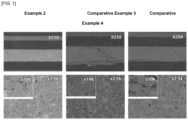
- FIG. 1 is a scanning electron micrograph of the side of the positive electrode of a mixture prepared in Example 2, Comparative Example 3, and Comparative Example 4.
- composite positive electrode may be referred to without a binder and “positive electrode” may be referred to with a binder.
- the present disclosure relates to a positive electrode for an all-solid-state battery.
- the positive electrode for an all-solid-state battery comprises a positive electrode active material, a sulfide-based solid electrolyte, a conductive material, and a porous carbon additive.
- the positive electrode may be in the form of a pellet.
- the pelletized positive electrode may be used in a current collector free form, or the pellets may be placed on top of a current collector to form a positive electrode.
- the pellets may be formed by pressing a composite powder comprising a positive electrode active material, a sulfide-based solid electrolyte, a conductive material, and a porous carbon additive.
- the pellets may comprise no binder, thereby excluding any resistance that may be caused by the binder.
- the positive electrode may comprise a positive electrode current collector and a positive electrode active material layer formed on one side of the positive electrode current collector.
- the positive electrode active material layer may include the positive electrode active material, a sulfide-based solid electrolyte, a conductive material, a binder, and a porous carbon additive.
- the particle diameter of the porous carbon additive is between the particle diameter of the positive electrode active material and the particle diameter of the sulfide-based solid electrolyte, and the porous carbon additive may have a BET specific surface area of 100 m 2 /g or less.
- the conductive material may be a linear conductive material, taking into account the specific surface area.
- a positive electrode that does not include a binder may correspond to a composite positive electrode.
- voids are formed due to a difference in the particle diameter between particles of the positive electrode active material and particles of a sulfide-based solid electrolyte, and the voids are filled with the porous carbon additive, so that the porosity of the positive electrode is reduced and the energy density can be improved. Since the particle diameter (D50) of the porous carbon additive is larger than the particle diameter (D50) of the sulfide-based solid electrolyte and smaller than the particle diameter (D50) of the positive electrode active material, the voids may be filled with the porous carbon additive.
- the porous carbon additive may have a BET specific surface area of 100 m 2 /g or less.
- the specific surface area of the porous carbon additive may have a BET specific surface area of 100 m 2 /g or less, 90 m 2 /g or less, 80 m 2 /g or less, 70 m 2 /g or less, 60 m 2 /g or less, 50 m 2 /g or less, 40 m 2 /g or less, or 30 m 2 /g or less.
- the contact interface between the high specific surface area porous carbon additive and the sulfide-based all-solid-state electrolyte for a positive electrode may be increased, which may increase the electrolyte degradation reaction and decrease the ionic conductivity of the positive electrode itself.
- the lower limit of the BET specific surface area is not particularly limited, but may be 5 m 2 /g or more.
- the porous carbon additive has a low specific surface area as defined above and may be referred to as macroporous carbon.
- the porous carbon additive may have a particle diameter (D50) of 1.0 ⁇ m to 4.0 ⁇ m.
- the particle diameter (D50) of the porous carbon additive may be 1.0 ⁇ m or more, 1.5 ⁇ m or more, or 2.0 ⁇ m or more, and may be 3.0 ⁇ m or less, 3.5 ⁇ m or less, or 4.0 ⁇ m or less.
- the particle diameter (D50) of the porous carbon additive is less than 1.0 ⁇ m, the particles are too small to fill the voids formed by the difference in particle diameter between the particles of the positive electrode active material and the sulfide-based solid electrolyte, and the porous carbon additive may be adsorbed only on the surface of the positive electrode active material, and if it is greater than 4.0 ⁇ m, it is difficult to fill the voids formed by the difference in particle diameter between the particles of the positive electrode active material and the sulfide-based solid electrolyte, and the effect of reducing the porosity of the positive electrode may be insignificant.
- the particle diameter (D50) can be measured by introducing the porous carbon additive into a particle size analyzer (Mastersizer 3000, Malvern).
- porous carbon additive may have a bulk density of 0.18 g/cc or greater.
- the bulk density may be greater than or equal to 0.18 g/cc, greater than or equal to 0.19 g/cc, or greater than or equal to 0.20 g/cc. If the bulk density is less than 0.18 g/cc, the porous carbon additive itself may have a lower density, thereby reducing the overall density of the positive electrode.
- the upper limit of the bulk density is not particularly limited, but may be 0.5 g/cc or less.
- the bulk density may be measured using a density meter conforming to ASTM D 1895.
- the powder resistivity of the porous carbon additive may be 0.05 ohm.cm or less.
- the powder resistivity may be 0.05 ohm/cm or less, 0.04 ohm/cm or less, or 0.03 ohm/cm or less. If the powder resistivity is greater than 0.05 ohm/cm, the resistance of the positive electrode as a whole may increase when the porous carbon additive in the positive electrode contains more than a certain fraction.
- the lower limit of the powder resistivity is not particularly limited, but may be greater than or equal to 0.005 ohm/cm.
- the powder resistance may be measured using a powder resistivity meter (HPRM-FA2, Hantech).
- HPRM-FA2, Hantech The powder resistivity meter is then operated to pressurize from 0 to 2000 kgf in 400 kgf increments, and the final powder resistivity at 2000 kgf (196 MPa) can be observed.
- the porous carbon additive may include one or more selected from the group consisting of soft carbon and hard carbon, but is not limited thereto as long as it is a carbon material in the particulate form.
- the porous carbon additive may be one or more selected from the group consisting of activated carbon and carbon black.
- the porous carbon additive may be included in an amount of 0.1 to 3% by weight based on the total weight of the positive electrode active material layer.
- the content of the porous carbon additive may be 0.1% by weight, 0.2% by weight or more, 0.3% by weight or more, 0.4% by weight or more, or 0.5% by weight or more, 1.2% by weight or less, 1.5% by weight or less, 2.0% by weight or less, 2.5% by weight or less, or 3.0% by weight or less. If the content of the porous carbon additive is less than 0.1% by weight, the energy density improvement due to the porosity reduced by the use of the porous carbon additive may be insignificant, and if the content is greater than 3% by weight, the mass transfer resistance may be larger.
- the particle diameter (D50) of the positive electrode active material may be 3.0 ⁇ m to 8.0 ⁇ m.
- the particle diameter (D50) of the positive electrode active material may be 3.0 ⁇ m or more, 3.5 ⁇ m or more, or 4.0 ⁇ m or more, and may be 6.0 ⁇ m or less, 6.5 ⁇ m or less, 7.0 ⁇ m or less, 7.5 ⁇ m or less, or 8.0 ⁇ m or less.
- the particle diameter (D50) of the positive electrode active material is less than 3.0 ⁇ m, even if the positive electrode active material and the all-solid-state electrolyte are dispersed in the same weight ratio, the dispersibility may be reduced due to the small particle diameter of the positive electrode active material, and if it is greater than 7.0 ⁇ m, voids may be formed in the positive electrode active material layer that are too large, and the performance of an all-solid-state battery may be reduced.
- the particle diameter (D50) can be measured by introducing the positive electrode active material into a particle size analyzer (Mastersizer 3000, Malvern).
- the positive electrode active material may be included in an amount of 55 to 90% by weight based on the total weight of the positive electrode active material layer.
- the content of the positive electrode active material may be 55% by weight, 60% by weight or more, or 65% by weight or more, 83% by weight or less, 85% by weight or less, or 90% by weight or less. If the content of the positive electrode active material is less than 55% by weight, the battery performance may be reduced, and if the content is greater than 90% by weight, the mass transfer resistance may be increased.
- the particle diameter (D50) of the sulfide-based solid electrolyte may be 0.1 ⁇ m to 1.5 ⁇ m.
- the particle diameter (D50) of the sulfide-based solid electrolyte may be 0.1 ⁇ m or more, 0.3 ⁇ m or more, or 0.5 ⁇ m or more, and may be 0.9 ⁇ m or less, 1.0 ⁇ m or less, 1.2 ⁇ m or less, or 1.5 ⁇ m or less.
- the ultra-fine all-solid-state electrolyte may not be sufficiently dispersed in the positive electrode layer and may agglomerate, and if it is greater than 1.5 ⁇ m, the dispersion may be somewhat easier, but the contact surface with the positive electrode active material particles may be reduced and the positive electrode porosity may increase.
- the sulfide-based solid electrolyte may comprise one or more selected from the group consisting of LiPSX (wherein X is Cl, Br, or I), LiGePS, and LiPS.
- LiPSX wherein X is Cl, Br, or I
- LiGePS LiGe-based solid electrolyte
- the sulfide-based solid electrolyte is not limited to these, and a wide range of sulfide-based solid electrolytes conventionally used in the art may be used.
- the sulfide-based solid electrolyte may be included in an amount of 10 to 50% by weight based on the total weight of the positive electrode active material layer.
- the content of the sulfide-based solid electrolyte may be 10% by weight or more, 20% by weight or more, or 30% by weight or more, and may be 40% by weight or less, 45% by weight or less, or 50% by weight or less.
- the content of the positive electrode active material is less than 10% by weight, it may not be sufficient to fill the voids formed in the positive electrode active material layer, making it difficult to reduce the porosity of the positive electrode active material, and if it is greater than 50% by weight, the content of the positive electrode active material and the conductive material may be relatively reduced, resulting in a decrease in the battery performance.
- the conductive material may be a linear conductive material, wherein the linear conductive material may be one or more selected from the group consisting of carbon nanotube (CNT) and carbon nanofiber (CNF).
- the linear conductive material may improve electrical conductivity due to its morphological characteristics.
- the conductive material may be included in an amount of 0.05 to 10% by weight based on the total weight of the positive electrode active material layer.
- the content of the conductive material may be 0.05% by weight or more, 0.1% by weight or more, 0.5% by weight or more, 1% by weight or more, 2% by weight or more, or 3% by weight or more, or may be 5% by weight or less, 7% by weight or less, or 10% by weight or less.
- the content of the conductive material is less than 0.05% by weight, the electrical conductivity of the positive electrode may be degraded, and if it is more than 10% by weight, the content of the positive electrode active material and the sulfide-based solid electrolyte may be relatively reduced, resulting in a degradation of the battery performance.
- the positive electrode active material layer may further comprise a binder.
- the binder may be included to facilitate bonding between the materials contained in the positive electrode active material layer and bonding between the positive electrode active material layer and the positive electrode current collector.
- the binder may further reduce the positive electrode porosity by promoting bonding between the materials included in the positive electrode active material layer.
- the binder may be a fibrous binder.
- the binder may be incorporated in a fibrous form in the positive electrode active material layer due to fibrosis during mixing in the manufacture of a positive electrode.
- the binder is easily deformable in its physical properties.
- the binder may comprise one or more selected from the group consisting of polytetrafluoroethylene (PTFE), polyethylene, polypropylene, ethylene/propylene copolymer, polybutadiene, polyethylene oxide, chlorosulfonated polyethylene, polyvinylpyrrolidone, polyvinylpyridine, polyvinyl alcohol, polyvinyl acetate, polypichlorohydrin, polyphosphazene, polyacrylonitrile, polystyrene, latex, acrylic resin, phenolic resin, epoxy resin, carboxymethylcellulose, hydroxypropyl cellulose, cellulose acetate, cellulose acetate butyrate, cellulose acetate propionate, cyanoethylcellulose, cyanoethyl sucrose, polyester, polyamide, polyether, polyimide, polycarboxylate, polycarboxylic acid, polyacrylic acid, polyacrylate, lithium polyacrylate, polymethacrylic acid, polymethacrylate, polyacrylamide, polyurethan
- the binder may be included in an amount of 0.1 to 3% by weight based on the total weight of the positive electrode active material layer.
- the content of the binder may be 0.1% by weight or more, 0.5% by weight or more, 0.8% by weight or more, or may be 1.5% by weight or less, 2% by weight or less, or 3% by weight or less. If the content of the binder is less than 0.1% by weight, the effect of improving the cohesion between the materials contained in the positive electrode active material layer is minimal and the electrode sheet may not be formed properly, and if the content is greater than 3% by weight, the ionic conductivity or electrical conductivity may be reduced.
- the porosity of the positive electrode active material layer may be 5 vol% to 19 vol%.
- the porosity may be 5 vol% or more, 8 vol% or more, 10 vol% or more, or 13 vol% or more, and may be 17 vol%, 18 vol% or less, or 19 vol% or less.
- the porosity is within the range optimized by considering performance such as the energy density of the battery, such that a porosity greater than 19 vol% may degrade the energy density of the battery.
- the thickness of the positive electrode active material layer may be 100 ⁇ m to 300 ⁇ m, more specifically, it may be 100 ⁇ m or more, 110 ⁇ m or more, 120 ⁇ m or more, 200 ⁇ m or less, 250 ⁇ m or less, or 300 ⁇ m or less.
- the thickness of the positive electrode active material layer is not limited thereto, and the thickness can be adjusted to have an appropriate positive electrode loading according to the performance improvement of the various positive electrode elements included in the positive electrode active material layer.
- the positive electrode current collector supports the positive electrode active material layer and serves to transfer electrons between the outer wire and the positive electrode active material layer.
- the positive electrode current collector is not particularly limited as long as it has a high electronic conductivity without causing chemical changes in an all-solid-state battery.
- stainless steel, aluminum, nickel, titanium, palladium, calcined carbon, stainless steel whose surface is treated with carbon, nickel, or silver, aluminum-cadmium alloy, and the like may be used as the positive electrode current collector.
- the positive electrode current collector may have a microscopic uneven structure or adopt a three-dimensional porous structure on the surface of the positive electrode current collector to strengthen the binding force with the positive electrode active material layer. Accordingly, the positive electrode current collector may comprise various forms such as film, sheet, foil, mesh, net, porous material, foam, nonwoven material, and the like.
- the present disclosure relates to a method of producing a positive electrode for an all-solid-state battery.
- the specific substances, properties, and contents of the positive electrode active material, sulfide-based solid electrolyte, conductive material, porous carbon additive, and binder used in the manufacturing method of the positive electrode for an all-solid-state battery according to the present disclosure are as described above.
- a positive electrode can be classified to a "composite positive electrode” without a binder or a “positive electrode” with a binder.
- a method for preparing a composite positive electrode without a binder may comprise (A1) mixing a positive electrode active material, a sulfide-based solid electrolyte, a conductive material, and a porous carbon additive; and (A2) preparing the mixed powder obtained in step (A1) in the form of a pellet.
- the pelletized form in step (A2) may be formed by pressing with a jig.
- the composite positive electrode prepared as described above can be applied to a pressure jig cell. Since the composite positive electrode does not include a binder, the factor that the binder acts as a resistance can be eliminated. Therefore, the composite positive electrode can be used to perform a performance evaluation using a pressure jig cell in which the resistance factor is eliminated.
- a method of manufacturing a positive electrode comprising a binder comprises (B1) mixing a positive electrode active material, a sulfide-based solid electrolyte, a conductive material, and a porous carbon additive binder; (B2) applying the mixed powder obtained in step (B1) to a calendaring process to form a film; and (B3) attaching the film-like layer of positive electrode active material obtained in step (B2) to a positive electrode current collector.
- the mixing in step (B1) may be physical mixing, wherein the binder may be fibersized by the physical mixing.
- the binder may be physically deformed by friction with the particles in the mixed powder by shear force, causing fibrosis.
- PTFE which has physical properties that can be easily deformed, can be used as a binder.
- physical deformation can be accomplished by introducing induction, ball milling, or roll pressing during mixing.
- step (B2) the mixed powder obtained in step (B1) may be subjected to a calendaring process to mold it into a film.
- the conditions of the calendering process may be the application of suitably controlled process conditions to form a film.
- the calendering process may be performed at a temperature of 50°C to 200°C and for 5 to 50 loops.
- the calendering process conditions such as temperature pressure, or number of loops, may be any of those used in electrode manufacturing processes used in the conventional battery field.
- step (B3) the positive electrode active material layer in the form of a film obtained in step (B2) is attached to the positive electrode current collector to prepare a positive electrode for an all-solid-state battery.
- the present disclosure relates to an all-solid-state battery comprising the solid electrolyte film.
- An all-solid-state battery includes the positive electrode, the negative electrode, and a sulfide-based solid electrolyte layer interposed therebetween.
- the positive electrode is as described above.
- the negative electrode comprises a negative electrode active material layer, wherein the negative electrode active material layer may be formed on one side of the negative electrode current collector.
- the negative electrode active material layer may comprise a negative electrode active material, a conductive material, and a binder.
- the negative electrode active material layer may be an anodeless layer.
- the negative electrode active material may comprise a material capable of reversibly intercalating or deintercalating lithium (Li + ), a material capable of reacting with lithium ions to reversibly form a lithium-containing compound, a lithium metal, or a lithium alloy.
- the material into which the lithium ions (Li + ) can be reversibly inserted or removed can be, for example, crystalline carbon, amorphous carbon, or a mixture thereof.
- the material capable of reacting with the lithium ions (Li + ) to reversibly form a lithium-containing compound may be, for example, tin oxide, titanium nitrate, or silicon.
- the lithium alloy may be, for example, an alloy of lithium (Li) and a metal selected from the group consisting of indium (In), sodium (Na), potassium (K), rubidium (Rb), cesium (Cs), francium (Fr), beryllium (Be), magnesium (Mg), calcium (Ca), strontium (Sr), barium (Ba), radium (Ra), aluminum (Al), and tin (Sn).
- a metal selected from the group consisting of indium (In), sodium (Na), potassium (K), rubidium (Rb), cesium (Cs), francium (Fr), beryllium (Be), magnesium (Mg), calcium (Ca), strontium (Sr), barium (Ba), radium (Ra), aluminum (Al), and tin (Sn).
- the negative electrode active material may be a lithium metal or a lithium-indium alloy (Li-In), more specifically, it may be in the form of a lithium metal or a lithium thin film or a lithium-indium alloy thin film or powder.
- Li-In lithium-indium alloy
- the negative electrode active material may be comprised in an amount of 40 to 80% by weight based on the total weight of the negative electrode active material layer.
- the content of the negative electrode active material may be 40% by weight or more, 50% by weight or more, or may be 70% by weight or less, or 80% by weight or less. If the content of the negative electrode active material is less than 40% by weight, the connectivity between the wet negative electrode active layer and the dry negative electrode active layer may be insufficient, and if the content is greater than 80% by weight, the mass transfer resistance may be greater.
- the binder is a component that assists in the bonding of the negative electrode active material and the conductive material or the bonding to a negative electrode current collector, and may comprise one or more selected from the group consisting of styrene-butadiene rubber, acrylated styrene-butadiene rubber, acrylonitrile copolymer, acrylonitrile-butadiene rubber, nitrile butadiene rubber, acrylonitrile-styrene-butadiene copolymer, acrylic rubber, butyl rubber, fluorine rubber, polytetrafluoroethylene, polyethylene, polypropylene, ethylene/propylene copolymer, polybutadiene, polyethylene oxide, chlorosulfonated polyethylene, polyvinylpyrrolidone, polyvinylpyridine, polyvinyl alcohol, polyvinyl acetate, polypichlorohydrin, polyphosphazene, polyacrylonitrile, polystyrene, latex,
- the binder may be comprised in an amount of 0.5% by weight to 4% by weight based on the total weight of the negative electrode active material layer, and more specifically, the content of the binder may be 0.5% by weight or more, 1% by weight or more, 1.5% by weight or more, 3% by weight or less, 3.5% by weight or less, or 4% by weight or less. If the binder content is less than 0.5% by weight, the adhesion of the positive electrode active material to the negative electrode current collector may be reduced, and if the binder content is greater than 4% by weight, the adhesion may be improved, but the content of the negative electrode active material may be reduced, resulting in a lower cell capacity.
- the conductive material is not particularly limited as long as it prevents side reactions in the internal environment of an all-solid-state battery and has excellent electrical conductivity without causing chemical changes in the battery
- graphite or conductive carbon can be used as a representative, for example, graphite such as natural graphite, artificial graphite, and the like; carbon black such as carbon black, acetylene black, ketjen black, denka black, thermal black, channel black, furnace black, lamp black, summer black, and the like; carbon-based materials having a crystal structure of graphene or graphite; conductive fibers such as carbon fibers, metal fibers, etc.; carbon fluorides; metal powders, such as aluminum powder, nickel powder, etc.; conductive whiskeys, such as zinc oxide, potassium titanate, etc.; conductive oxides, such as titanium oxide; and conductive polymers, such as polyphenylene derivatives; can be used alone or in a mixture of two or more of the foregoing, but are not necessarily limited thereto.
- the conductive material
- the conductive material may be comprised in an amount of 1% by weight to 5% by weight based on the total weight of the negative electrode active material layer, and more specifically, the content of the binder may be 1% by weight or more, 1.5% by weight or more, 2% by weight or more, and may be 4% by weight or less, 4.5% by weight or less, or 5% by weight or less. If the content of the conductive material is too small, such as less than 1% by weight, it is difficult to expect the effect of improving the electrical conductivity or the electrochemical properties of the battery may be degraded, and if it is too large, such as more than 5% by weight, the amount of negative electrode active material may be relatively small, resulting in a decrease in capacity and energy density.
- the method of incorporating the conductive material into the negative electrode is not substantially limited, and any conventional method known in the art can be used, such as mixing with or coating the negative electrode active material.
- the negative electrode current collector is not particularly limited as long as it is conductive without causing chemical changes in the battery, for example, copper, stainless steel, aluminum, nickel, titanium, calcined carbon, copper or stainless steel whose surface is treated with carbon, nickel, or silver, aluminum-cadmium alloy, and the like can be used.
- the negative electrode current collector can be in various forms, such as a film, sheet, foil, net, porous material, foam, nonwoven material, etc. with fine irregularities formed on the surface.
- the method of manufacturing a negative electrode is not particularly limited, and can be manufactured by forming a negative electrode active material layer on the negative electrode current collector using a conventional method of forming a layer or a film. For example, methods such as pressing, coating, or deposition can be utilized.
- the negative electrode of the present disclosure also includes a case in which a metallic lithium thin film is formed on a metal plate by initial charging after the battery is assembled without a lithium thin film on the negative electrode current collector.
- the anodeless layer refers to a negative electrode layer in which no lithium metal or lithium alloy that can be a source of lithium among the negative electrode active materials is present in the negative electrode at the time of initial assembly of the battery, but lithium is precipitated in the negative electrode by charging.
- a battery comprising the anodeless layer may be referred to as a negative electrode-free battery.
- lithium ions released from the positive electrode migrate to the negative electrode to form a negative electrode active material layer.
- lithium ions are released from the positive electrode active material and migrate to the negative electrode side to form a lithium metal consisting purely of lithium, forming a lithium metal layer on the negative electrode current collector, or forming a lithium metal structure in any other form other than a layer form.
- Any other form may refer to, for example, a structure in which the lithium metal is agglomerated in the form of particles.
- the sulfide-based solid electrolyte comprised in the sulfide-based solid electrolyte layer may comprise one or more selected from the group consisting of LiPSX (wherein X is Cl, Br, or I), LiGePS, and LiPS.
- LiPSX wherein X is Cl, Br, or I
- LiGePS LiGe-based solid electrolyte
- the sulfide-based solid electrolyte is not limited to these, and a wide range of sulfide-based solid electrolytes conventionally used in the art may be used.
- the present disclosure also relates to a battery module comprising the all-solid-state battery as a unit cell, a battery pack comprising the battery module, and a device comprising the battery pack as a power source.
- Such devices include, but are not limited to, a power tool powered by an electric motor; an electric vehicle, including an electric vehicle (EV), a hybrid electric vehicle (HEV), a plug-in hybrid electric vehicle (PHEV), and the like; an electric two-wheeled vehicle, including an electric bicycle (E-bike) and an electric scooter (E-scooter); an electric golf cart; a power storage system; and the like.
- an electric vehicle including an electric vehicle (EV), a hybrid electric vehicle (HEV), a plug-in hybrid electric vehicle (PHEV), and the like
- an electric two-wheeled vehicle including an electric bicycle (E-bike) and an electric scooter (E-scooter)
- E-scooter electric bicycle
- an electric scooter E-scooter
- a positive electrode and an all-solid-state battery comprising same were prepared according to the composition of the positive electrode active material layer and the properties of the raw material as described in Table 1 below.
- Table 1 Composition of positive electrode active material layer (weight%) Properties of raw material Porous carbon additive Positive electrode active material Sulfide-based solid electrolyte Positive electrode active material Sulfide-based solid electrolyte Conductive material Porous carbon additive Binder BET specific surface area (m 2 /g) Particle diameter (D50) ( ⁇ m) Particle diameter (D50) ( ⁇ m) Particle diameter (D50) ( ⁇ m) ( ⁇ m)
- Example 1 60 35 4 1 - 60 m 2 /g or less 1.7 1) 5.3 0.8
- the porous carbon additive used in Comparative Example 4 has a smaller particle diameter compared to the low specific surface area porous additive 1, and is referred to as "low specific surface area porous additive 2" for distinction.
- the porous carbon additive used in Comparative Example 2 is referred to as "high specific surface area porous additive”.
- Example 1 Preparation of a composite positive electrode
- the positive electrode was prepared as follows using LiN 0.8 Co 0.1 Mn 0.1 O 2 (NCM 811) as a positive electrode active material, Li 6 PS 5 Cl as a sulfide-based solid electrolyte, and a carbon nanofiber (CNF) as a linear conductive material and a porous carbon additive (Heraeus, BET ⁇ 60 m 2 /g) as a conductive material.
- the porous carbon additive is referred to as low specific surface area porous carbon additive 1.
- Powder mixing of the positive electrode active material, sulfide-based solid electrolyte, conductive material, and porous carbon additive was performed in a weight ratio of 60 : 35 : 4 : 1. Specifically, the positive electrode active material and the sulfide-based solid electrolyte were quantified in a powder state and mixed for 15 minutes using agate mortar in a dry room environment to obtain a mixture. The conductive material and porous carbon additive were then quantified and added to the above mixture and mixed for an additional 15 minutes to obtain a mixed powder.
- the above mixed powder was pressurized and prepared into a pelletized composite positive electrode with a 3 mAh/cm 2 loading.
- the positive electrode was prepared as follows using LiN 0.8 Co 0.1 Mn 0.1 O 2 (NCM 811) as a positive electrode active material, Li 6 PS 5 Cl as a sulfide-based solid electrolyte, and a carbon nanofiber (CNF) as a linear conductive material as a conductive material, low specific surface area porous carbon additive 1 (Heraeus, BET ⁇ 60 m 2 /g) as a porous carbon additive, and polytetrafluoroethylene (PTFE) as a binder.
- NCM 811 LiN 0.8 Co 0.1 Mn 0.1 O 2
- Li 6 PS 5 Cl as a sulfide-based solid electrolyte
- CNF carbon nanofiber
- low specific surface area porous carbon additive 1 Heraeus, BET ⁇ 60 m 2 /g
- PTFE polytetrafluoroethylene
- Powder mixing of the positive electrode active material, sulfide-based solid electrolyte, conductive material, porous carbon additive, and binder was performed in a weight ratio of 83 : 15 : 0.8 : 0.2 : 1.
- the positive electrode active material and the sulfide-based solid electrolyte were quantified in a powder state and mixed for 15 minutes using a blade mixer in a dry room environment to obtain a mixture.
- the conductive material and low porous carbon additive 1 were then quantified and added to the above mixture and the binder, polytetrafluoroethylene (PTFE) powder, was quantified and further mixed to obtain a mixed powder.
- PTFE polytetrafluoroethylene
- the composite positive electrode was prepared in the same manner as in Example 1, except that no porous carbon additive was used.
- the composite positive electrode was prepared in the same manner as in Example 1, except that a high specific surface area porous carbon additive (Heraeus, BET ⁇ 500 m 2 /g) was used instead of low specific surface area porous carbon additive 1 as a porous carbon additive.
- a high specific surface area porous carbon additive Heraeus, BET ⁇ 500 m 2 /g
- the positive electrode was prepared in the same manner as in Example 2, except that no porous carbon additive was used.
- the positive electrode was prepared in the same manner as in Example 2, except that a porous carbon additive (Heraeus, BET ⁇ 60 m 2 /g) with a small particle diameter compared to the porous carbon additive (low specific surface area porous carbon additive 1) used in Example 2 was used.
- a porous carbon additive Heraeus, BET ⁇ 60 m 2 /g
- the porous carbon additive with a smaller particle diameter than the low specific surface area porous carbon additive 1 is referred to as low specific surface area porous carbon additive 2.
- a pressure jig cell was prepared by the following method.
- a sulfide-based solid electrolyte powder 200 mg was placed on the pellet and pressurized with a force of 400 Mpa for 60 seconds to form a film-like sulfide-based solid electrolyte layer. Then, a lithium metal negative electrode was placed on one side of the sulfide-based solid electrolyte layer, and pressurized again with a force of 100 Mpa to increase the contact between the sulfide-based solid electrolyte layer and the negative electrode. Afterward, the pressure jig cell was prepared by clamping at an appropriate pressure.
- the capacity capability of the pressure jig cell was observed using the protocol of activating the cell in a charger/discharger to 0.05C for 2 cycles, and then discharging it up to 1C, and the results are shown in Table 2 and Table 3 below. Specifically, the capacity capability was observed using the protocol of 0.05C CC/CV (Constant Current/Constant Voltage) charging, 0.05C CC (Constant Current) discharging for 2 cycles, followed by 0.1C CC/CV charging, but CC discharging to 0.1C/0.2C/0.33C/0.5C/1C, in a charger/discharger.
- 0.05C CC/CV Constant Current/Constant Voltage
- 0.05C CC Constant Current
- CC Constant Current
- Example 1 and Comparative Example 1 with and without low specific surface area porous carbon additive 1, respectively, exhibited superior performance in terms of discharge capacity compared to Comparative Example 1 after formation for 2 cycles.
- Example 1 and Comparative Example 2 include low specific surface area porous carbon additive 1 and high specific surface area porous carbon additive 2, respectively, and it can be seen that the initial efficiency of Comparative Example 2 is on par with Comparative Example 1, but the discharge capacity is somewhat inferior.
- Example 1 has a better discharge capacity retention compared to Comparative Example 1 and Comparative Example 2. Specifically, Example 1 maintained a discharge capacity of 185 mAh/g at 1C discharge, while Comparative Example 1 and Comparative Example 2 measured discharge capacities of 170 mAh/g or less. This is due to the phenomenon that when the specific surface area of the porous carbon additive in the composite positive electrode is high (Comparative Example 2), the decomposition reaction of the sulfide-based solid electrolyte in contact with the porous carbon additive is accelerated with increasing c-rate.
- the conductive network is sufficiently formed due to the use of a linear conductive material, but the porosity of the composite positive electrode in the pressure jig cell may be higher than that of the positive electrode with a porous carbon additive, and it can be inferred that the lithium ion conductivity is reduced, resulting in a reduced discharge capacity retention.
- Example 2 Comparative Example 3 and Comparative Example 4 were subject to evaluation. They all contain a binder in the positive electrode active material layer.
- Example 2 The positive electrodes made according to Example 2, Comparative Example 3, and Comparative Example 4 were further pressurized using a warm isostatic press (WIP) to bring the positive electrode elements into full contact, and the sides of the positive electrodes were observed with a scanning electron microscope (SEM).
- WIP warm isostatic press
- SEM scanning electron microscope
- Example 2 Comparative Example 3, and Comparative Example 4 are all examples of using a binder in the manufacture of the positive electrode, wherein Example 2 includes a low specific surface area porous carbon additive 1, Comparative Example 3 does not include a porous carbon additive, and Comparative Example 4 includes a low specific surface area porous carbon additive 2 with a smaller particle diameter compared to Example 2.
- FIG. 1 is a scanning electron micrograph of the side of the positive electrode made by using a positive electrode material in Example 2, Comparative Example 3, and Comparative Example 4.
- Example 2 and Comparative Example 4 including the porous carbon additive did not reduce the dispersibility of the components included in the positive electrode active material layer, particularly compared to Comparative Example 3, which does not include the porous carbon additive.
- porosity was measured before and after rolling the WIP, and electrical conductivity was measured using the fabricated positive electrode, and the results are shown in Table 4 below.
- the porosity was measured using the positive electrode density calculated from 1) the thickness after WIP rolling of the positive electrode, 2) the weight of the positive electrode, 3) the area of the positive electrode, and 4) the density of the positive electrode elements used, according to Formula 1 below.
- Positive electrode porosity (%) (1-([positive electrode weight]/[positive electrode area x positive electrode thickness]/[positive electrode density] x 100)
- the electrical conductivity (S/cm) was measured by making an electrode for electrical conductivity measurement by preparing a positive electrode, and then contacting an electrically conductive Al foil on one side of the positive electrode and then pressing it with WIP, and then calculating the inverse of the resistance value (ohm ⁇ cm) obtained by contacting the multi probe of the electrode resistance measurement system (RM2610, Hioki), and the average value after three measurements was written.
- Example 2 Comparative Example 3 Comparative Example 4 Porosity after rolling (vol%) 16 19.2 20.5 Electrical conductivity (S/cm) 5.9.
- E-05 5.0.
- Example 2 comprising low specific surface area porous carbon additive 1 decreased by about 3 vol% compared to that before rolling, compared to Comparative Example 3, which does not include a porous carbon additive.
- the electrical conductivity measured using the positive electrode of Example 2 was also found to be greater than those of Comparative Examples 3 and 4.
- the positive electrode of Comparative Example 4 which includes a low specific surface area porous carbon additive 2 having a smaller particle diameter compared to the low specific surface area porous carbon additive 1 of Example 2, showed a rather increased porosity after rolling and the lowest electrical conductivity.
- the low specific surface area porous carbon additive 1 (D50, 1.7 ⁇ m) used in Example 2 has a particle diameter between the positive electrode active material (D50, 5 ⁇ m) and the sulfide-based solid electrolyte (D50, 0.7 ⁇ m).
- the low specific surface area porous carbon additive 2 used in Comparative Example 4 had a smaller particle diameter compared to the low specific surface area porous carbon additive 1 of Example 2, and was therefore expected to more effectively fill the pores formed by the positive electrode active material and the sulfide-based solid electrolyte, but due to its very low particle diameter and the resulting fine powder, it was found that it only adsorbed on the surface of the positive electrode active material and did not reduce the porosity of the entire positive electrode active material layer.
- the low specific surface area porous carbon additive 1 used in Example 2 will reduce the porosity of the positive electrode active material layer and thereby increase the performance of the positive electrode.
Landscapes
- Chemical & Material Sciences (AREA)
- Chemical Kinetics & Catalysis (AREA)
- Electrochemistry (AREA)
- General Chemical & Material Sciences (AREA)
- Engineering & Computer Science (AREA)
- Manufacturing & Machinery (AREA)
- Materials Engineering (AREA)
- Physics & Mathematics (AREA)
- General Physics & Mathematics (AREA)
- Inorganic Chemistry (AREA)
- Condensed Matter Physics & Semiconductors (AREA)
- Battery Electrode And Active Subsutance (AREA)
- Secondary Cells (AREA)
Applications Claiming Priority (2)
| Application Number | Priority Date | Filing Date | Title |
|---|---|---|---|
| KR1020230094993A KR20250014633A (ko) | 2023-07-21 | 2023-07-21 | 전고체 전지용 양극 및 이를 포함하는 전고체 전지 |
| PCT/KR2024/009560 WO2025023553A1 (ko) | 2023-07-21 | 2024-07-05 | 전고체 전지용 양극 및 이를 포함하는 전고체 전지 |
Publications (2)
| Publication Number | Publication Date |
|---|---|
| EP4567959A1 true EP4567959A1 (de) | 2025-06-11 |
| EP4567959A4 EP4567959A4 (de) | 2026-03-04 |
Family
ID=94374793
Family Applications (1)
| Application Number | Title | Priority Date | Filing Date |
|---|---|---|---|
| EP24845857.2A Pending EP4567959A4 (de) | 2023-07-21 | 2024-07-05 | Positivelektrode für festkörperbatterie und festkörperbatterie damit |
Country Status (5)
| Country | Link |
|---|---|
| EP (1) | EP4567959A4 (de) |
| JP (1) | JP7848409B2 (de) |
| KR (1) | KR20250014633A (de) |
| CN (1) | CN119895624A (de) |
| WO (1) | WO2025023553A1 (de) |
Cited By (1)
| Publication number | Priority date | Publication date | Assignee | Title |
|---|---|---|---|---|
| EP4576272A4 (de) * | 2023-09-12 | 2026-04-08 | Lg Energy Solution Ltd | Kathode für festkörperbatterie und festkörperbatterie damit |
Family Cites Families (12)
| Publication number | Priority date | Publication date | Assignee | Title |
|---|---|---|---|---|
| KR101851317B1 (ko) * | 2011-07-26 | 2018-05-31 | 삼성전자주식회사 | 다공성 탄소계 복합재료, 이를 포함하는 양극 및 리튬공기전지, 및 이의 제조방법 |
| JP5912551B2 (ja) * | 2012-01-11 | 2016-04-27 | 出光興産株式会社 | 電極材料、電極及びそれを用いた電池 |
| JP2015076387A (ja) * | 2013-10-11 | 2015-04-20 | トヨタ自動車株式会社 | 電極の製造方法、および電極 |
| KR20160118597A (ko) | 2015-04-02 | 2016-10-12 | 현대자동차주식회사 | 산화 그래핀이 적용된 전고체 리튬황 이차전지 양극 및 이의 제조방법 |
| KR101923466B1 (ko) * | 2015-09-10 | 2018-11-30 | 주식회사 엘지화학 | 이차전지용 도전재 및 이를 포함하는 이차전지 |
| KR102259971B1 (ko) * | 2017-10-20 | 2021-06-02 | 주식회사 엘지에너지솔루션 | 음극 활물질 및 이를 포함하는 전고체 전지용 음극 |
| EP3993109A4 (de) * | 2019-06-28 | 2022-12-07 | Teijin Limited | Kohlenstoffasern enthaltende aktivmaterialschicht für lithium-feststoffsekundärbatterie und lithium-feststoffsekundärbatterie |
| KR102937840B1 (ko) * | 2019-11-11 | 2026-03-10 | 삼성에스디아이 주식회사 | 전고체 이차전지 |
| JP7384071B2 (ja) * | 2020-02-28 | 2023-11-21 | Agc株式会社 | リチウムイオン二次電池に用いられる正極層及びリチウムイオン二次電池 |
| CN115516660A (zh) * | 2020-03-24 | 2022-12-23 | 株式会社杰士汤浅国际 | 蓄电元件用正极和蓄电元件 |
| JP7752476B2 (ja) * | 2021-02-01 | 2025-10-10 | パナソニックホールディングス株式会社 | 固体電池用負極、固体電池および固体電池用負極の製造方法 |
| KR102912261B1 (ko) | 2021-12-20 | 2026-01-15 | 주식회사 바이브존 | 컨텐츠 거래 제공 방법 및 이를 이용한 장치 |
-
2023
- 2023-07-21 KR KR1020230094993A patent/KR20250014633A/ko active Pending
-
2024
- 2024-07-05 JP JP2025522059A patent/JP7848409B2/ja active Active
- 2024-07-05 EP EP24845857.2A patent/EP4567959A4/de active Pending
- 2024-07-05 WO PCT/KR2024/009560 patent/WO2025023553A1/ko active Pending
- 2024-07-05 CN CN202480004003.4A patent/CN119895624A/zh active Pending
Cited By (1)
| Publication number | Priority date | Publication date | Assignee | Title |
|---|---|---|---|---|
| EP4576272A4 (de) * | 2023-09-12 | 2026-04-08 | Lg Energy Solution Ltd | Kathode für festkörperbatterie und festkörperbatterie damit |
Also Published As
| Publication number | Publication date |
|---|---|
| EP4567959A4 (de) | 2026-03-04 |
| WO2025023553A1 (ko) | 2025-01-30 |
| KR20250014633A (ko) | 2025-02-03 |
| JP7848409B2 (ja) | 2026-04-20 |
| CN119895624A (zh) | 2025-04-25 |
| JP2025535305A (ja) | 2025-10-24 |
Similar Documents
| Publication | Publication Date | Title |
|---|---|---|
| JP6755736B2 (ja) | 電極活物質スラリー、その製造方法及び該電極活物質スラリーを含む全固体二次電池 | |
| Rahman et al. | A review on porous negative electrodes for high performance lithium-ion batteries | |
| CN104025347A (zh) | 电极材料、电极板、锂离子电池以及电极材料的制造方法、电极板的制造方法 | |
| JP7715945B2 (ja) | 全固体電池用正極およびそれを含む全固体電池 | |
| CN117747822A (zh) | 补锂添加剂及其制备方法、正极极片及二次电池 | |
| EP4567959A1 (de) | Positivelektrode für festkörperbatterie und festkörperbatterie damit | |
| KR20200098860A (ko) | 괴타이트를 포함하는 리튬 이차전지용 양극 및 이를 구비한 리튬 이차전지 | |
| EP4447181A1 (de) | Festelektrolytmembran und feststoffbatterie damit | |
| JP7841189B2 (ja) | 全固体電池用正極及びこれを含む全固体電池 | |
| KR20230065391A (ko) | 단일벽 탄소나노튜브가 적용된 음극 및 이를 포함하는 이차전지 | |
| EP4571873A1 (de) | Kathode für festkörperbatterie und festkörperbatterie damit | |
| EP4586337A1 (de) | Kathodenmaterial für festkörperbatterie, kathode und festkörperbatterie | |
| US20250158035A1 (en) | Positive electrode active material for all-solid-state battery, positive electrode for all-solid-state battery, and all-solid-state battery comprising the same | |
| US20260128321A1 (en) | Positive electrode active material for all-solid-state battery, positive electrode and all-solid-state battery | |
| EP4636898A1 (de) | Festkörperbatterie und herstellungsverfahren dafür | |
| KR20260044283A (ko) | 전고체 전지용 양극 및 이를 포함하는 전고체 전지 | |
| EP4641734A1 (de) | Sulfidbasierter festelektrolyt und feststoffbatterie damit | |
| KR20260043766A (ko) | 에너지 저장장치용 전극 및 이를 포함하는 에너지 저장장치 | |
| KR20240077784A (ko) | 복합 고체 전해질, 이의 제조방법 및 이를 포함하는 전고체 전지 | |
| KR20260030011A (ko) | 전고체 전지용 양극 및 이를 포함하는 전고체 전지 | |
| KR20260062891A (ko) | 전고체 전지용 양극 활물질, 이를 포함하는 전고체 전지용 양극 및 전고체 전지 | |
| EP4685903A1 (de) | Festelektrolytmembran, verfahren zur herstellung davon und feststoffbatterie damit | |
| JP2026508468A (ja) | 全固体電池用正極及びそれを含む全固体電池 | |
| JP2026510739A (ja) | リチウム二次電池用極板及びこれを含むリチウム二次電池 | |
| KR20260027840A (ko) | 전고체 전지용 양극 활물질, 이를 포함하는 양극 및 전고체 전지 |
Legal Events
| Date | Code | Title | Description |
|---|---|---|---|
| STAA | Information on the status of an ep patent application or granted ep patent |
Free format text: STATUS: THE INTERNATIONAL PUBLICATION HAS BEEN MADE |
|
| PUAI | Public reference made under article 153(3) epc to a published international application that has entered the european phase |
Free format text: ORIGINAL CODE: 0009012 |
|
| STAA | Information on the status of an ep patent application or granted ep patent |
Free format text: STATUS: REQUEST FOR EXAMINATION WAS MADE |
|
| 17P | Request for examination filed |
Effective date: 20250307 |
|
| AK | Designated contracting states |
Kind code of ref document: A1 Designated state(s): AL AT BE BG CH CY CZ DE DK EE ES FI FR GB GR HR HU IE IS IT LI LT LU LV MC ME MK MT NL NO PL PT RO RS SE SI SK SM TR |
|
| A4 | Supplementary search report drawn up and despatched |
Effective date: 20260204 |
|
| RIC1 | Information provided on ipc code assigned before grant |
Ipc: H01M 10/42 20060101AFI20260129BHEP Ipc: H01M 4/13 20100101ALI20260129BHEP Ipc: H01M 4/62 20060101ALI20260129BHEP Ipc: H01M 10/052 20100101ALI20260129BHEP Ipc: H01M 4/02 20060101ALI20260129BHEP Ipc: H01M 10/0525 20100101ALI20260129BHEP Ipc: H01M 10/0562 20100101ALI20260129BHEP Ipc: H01M 4/04 20060101ALI20260129BHEP Ipc: H01G 11/24 20130101ALN20260129BHEP Ipc: H01G 11/42 20130101ALN20260129BHEP Ipc: H01G 11/56 20130101ALN20260129BHEP |