EP4568101A2 - Automatische bestimmung von steuerparametern für einen spannungsregler einer synchronmaschine - Google Patents
Automatische bestimmung von steuerparametern für einen spannungsregler einer synchronmaschine Download PDFInfo
- Publication number
- EP4568101A2 EP4568101A2 EP25171892.0A EP25171892A EP4568101A2 EP 4568101 A2 EP4568101 A2 EP 4568101A2 EP 25171892 A EP25171892 A EP 25171892A EP 4568101 A2 EP4568101 A2 EP 4568101A2
- Authority
- EP
- European Patent Office
- Prior art keywords
- transfer function
- synchronous machine
- coefficients
- time series
- voltage regulator
- Prior art date
- Legal status (The legal status is an assumption and is not a legal conclusion. Google has not performed a legal analysis and makes no representation as to the accuracy of the status listed.)
- Pending
Links
Images
Classifications
-
- H—ELECTRICITY
- H02—GENERATION; CONVERSION OR DISTRIBUTION OF ELECTRIC POWER
- H02P—CONTROL OR REGULATION OF ELECTRIC MOTORS, ELECTRIC GENERATORS OR DYNAMO-ELECTRIC CONVERTERS; CONTROLLING TRANSFORMERS, REACTORS OR CHOKE COILS
- H02P23/00—Arrangements or methods for the control of AC motors characterised by a control method other than vector control
- H02P23/14—Estimation or adaptation of motor parameters, e.g. rotor time constant, flux, speed, current or voltage
-
- G—PHYSICS
- G05—CONTROLLING; REGULATING
- G05B—CONTROL OR REGULATING SYSTEMS IN GENERAL; FUNCTIONAL ELEMENTS OF SUCH SYSTEMS; MONITORING OR TESTING ARRANGEMENTS FOR SUCH SYSTEMS OR ELEMENTS
- G05B11/00—Automatic controllers
- G05B11/01—Automatic controllers electric
- G05B11/36—Automatic controllers electric with provision for obtaining particular characteristics, e.g. proportional, integral, differential
- G05B11/42—Automatic controllers electric with provision for obtaining particular characteristics, e.g. proportional, integral, differential for obtaining a characteristic which is both proportional and time-dependent, e.g. P. I., P. I. D.
-
- G—PHYSICS
- G05—CONTROLLING; REGULATING
- G05B—CONTROL OR REGULATING SYSTEMS IN GENERAL; FUNCTIONAL ELEMENTS OF SUCH SYSTEMS; MONITORING OR TESTING ARRANGEMENTS FOR SUCH SYSTEMS OR ELEMENTS
- G05B13/00—Adaptive control systems, i.e. systems automatically adjusting themselves to have a performance which is optimum according to some preassigned criterion
- G05B13/02—Adaptive control systems, i.e. systems automatically adjusting themselves to have a performance which is optimum according to some preassigned criterion electric
- G05B13/04—Adaptive control systems, i.e. systems automatically adjusting themselves to have a performance which is optimum according to some preassigned criterion electric involving the use of models or simulators
- G05B13/042—Adaptive control systems, i.e. systems automatically adjusting themselves to have a performance which is optimum according to some preassigned criterion electric involving the use of models or simulators in which a parameter or coefficient is automatically adjusted to optimise the performance
- G05B13/045—Adaptive control systems, i.e. systems automatically adjusting themselves to have a performance which is optimum according to some preassigned criterion electric involving the use of models or simulators in which a parameter or coefficient is automatically adjusted to optimise the performance using a perturbation signal
-
- H—ELECTRICITY
- H02—GENERATION; CONVERSION OR DISTRIBUTION OF ELECTRIC POWER
- H02P—CONTROL OR REGULATION OF ELECTRIC MOTORS, ELECTRIC GENERATORS OR DYNAMO-ELECTRIC CONVERTERS; CONTROLLING TRANSFORMERS, REACTORS OR CHOKE COILS
- H02P25/00—Arrangements or methods for the control of AC motors characterised by the kind of AC motor or by structural details
- H02P25/02—Arrangements or methods for the control of AC motors characterised by the kind of AC motor or by structural details characterised by the kind of motor
- H02P25/022—Synchronous motors
-
- H—ELECTRICITY
- H02—GENERATION; CONVERSION OR DISTRIBUTION OF ELECTRIC POWER
- H02P—CONTROL OR REGULATION OF ELECTRIC MOTORS, ELECTRIC GENERATORS OR DYNAMO-ELECTRIC CONVERTERS; CONTROLLING TRANSFORMERS, REACTORS OR CHOKE COILS
- H02P25/00—Arrangements or methods for the control of AC motors characterised by the kind of AC motor or by structural details
- H02P25/02—Arrangements or methods for the control of AC motors characterised by the kind of AC motor or by structural details characterised by the kind of motor
- H02P25/022—Synchronous motors
- H02P25/03—Synchronous motors with brushless excitation
-
- H—ELECTRICITY
- H02—GENERATION; CONVERSION OR DISTRIBUTION OF ELECTRIC POWER
- H02P—CONTROL OR REGULATION OF ELECTRIC MOTORS, ELECTRIC GENERATORS OR DYNAMO-ELECTRIC CONVERTERS; CONTROLLING TRANSFORMERS, REACTORS OR CHOKE COILS
- H02P9/00—Arrangements for controlling electric generators for the purpose of obtaining a desired output
- H02P9/10—Control effected upon generator excitation circuit to reduce harmful effects of overloads or transients, e.g. sudden application of load, sudden removal of load, sudden change of load
- H02P9/102—Control effected upon generator excitation circuit to reduce harmful effects of overloads or transients, e.g. sudden application of load, sudden removal of load, sudden change of load for limiting effects of transients
Definitions
- the invention relates to the field of synchronous electrical machines.
- the invention relates to a method, a computer program and a computer-readable medium for determining control parameters for a voltage regulator of a synchronous electrical machines as well as to a synchronous electrical machines with such a voltage regulator.
- An automatic voltage regulator which regulates the magnitude of a three phase alternating voltage at the terminals of a synchronous generator, whose field windings are possibly energized by an exciter machine, usually comprise a PID controller.
- the control parameters of the PID controller may have to be adjusted during commissioning of the synchronous generator.
- control parameters in the third step may be problematic.
- the methods to compute the control parameters may be either quite restrictive with respect to the achievable controller performance or may result again in a tedious time consuming trial-and-error approach.
- WO 2009/097 605 A1 describes a digital excitation control system, in which a transfer function model is determined with a least square method and the control parameters are derived therefrom with pole zero cancellation.
- US 2002 040 250 A1 and EP 0 263 616 A2 relate to methods for adjusting parameters of controllers based on regression analysis.
- An aspect of the invention relates to a method for determining control parameters for a voltage regulator of a synchronous machine.
- control parameters of an automatic voltage regulator may be automatically computed.
- the voltage regulator may be used to regulate an magnitude of a three-phase alternating terminal voltage of a synchronous generator at a desired level.
- the synchronous machine may comprise a stator with stator windings connected with stator terminals to an electrical grid and a rotor with rotor windings rotatable mounted in the stator.
- the (automatic) voltage regulator may be adapted for outputting an excitation signal to adjust a current in the rotor windings for controlling the synchronous machine, such that a terminal voltage in the stator terminals is controlled.
- the excitation signal may be a voltage signal applied to the rotor windings themselves or a voltage signal applied to an exciting system which is coupled to the rotor.
- a terminal voltage in the stator terminals may be adjusted and/or controlled. Further control objectives of the voltage regulator may be the reactive power and/or the power factor of the synchronous machine.
- the method may be automatically performed by a controller, which may be part of the voltage regulator.
- the control parameters may be parameter of a further controller and/or control part of the voltage regulator.
- control parameters may be determined in three steps.
- the method comprises: in a first step, receiving a first time series of values of the excitation signal and a second time series of measurement values of the terminal voltage, wherein the first time series and the second time series acquired over a time interval.
- the synchronous machine such as a generator, may be excited, possibly through an exciter system.
- the synchronous machine may be excited at a fixed operating point and the terminal voltage together with the excitation signal may be recorded.
- the first and second time series may comprise values acquired at consecutive and/or equally distant time instant.
- the method comprises: in a second step, determining coefficients of a system transfer function of the synchronous machine, wherein the system transfer function is a rational function, wherein the coefficients of the system transfer function are determined recursively with a regression analysis with instrumental variables.
- the first time series may be considered as system input and the second time series may be considered as system output.
- the system transfer function may be provided in the Laplace transformed system. It may be that the first and second time series are Laplace transformed before they are input into the regression analysis.
- the simply refined instrumental variable method may be used.
- the instrumental variable method a continuous-time transfer function may be identified.
- the system transfer function may be determined for the small-signal behavior of the system around a given operating point using the recorded data from the first step.
- the instrumental variable method may not lead to biased parameter estimates like an (recursive) least squares approach. Furthermore, it may not require expert knowledge in manually tuning the algorithm. Moreover, the instrumental variable method may require only a few solutions of initial value problems to find the coefficients of the system transfer function. For example, less than 25 initial value problems may have to be solved until the algorithm terminates.
- the method comprises: in a third step, determining the control parameters for the voltage regulator from the coefficients of the system transfer function by comparing a closed loop transfer function formed of a controller transfer function of the voltage regulator and the system transfer function with a desired closed loop transfer function.
- the controller transfer function may be the transfer function of a controller of the voltage regulator for which the control coefficients are determined. Therefore, the controller transfer function may depend on the controller parameters. From the controller transfer function and the system transfer function an open loop transfer function may be determined, for example by multiplying the two transfer function. From the open loop transfer function, the closed loop transfer function may be determined. In the end, one may assume that the closed loop transfer function is equal to a desired closed loop transfer function with known coefficients, such as transfer function of a first order or second order system. For example, the desired coefficients of the desired transfer function may be a desired settling time and/or a desired overshoot. From this, the control parameter can be computed from the desired coefficients of the desired closed loop transfer function and the coefficients of the system transfer function.
- the coefficients of the system transfer function are recursively determined by: calculating an actual step excitation signal by filtering the previous step excitation signal with a denominator of the system transfer function with actual step coefficients, and calculating an actual step terminal voltage by filtering a previous step terminal voltage with the denominator of the system transfer function with actual step coefficients.
- all these functions and signals may be evaluated in the Laplace domain.
- higher order derivatives of the excitation signal and the terminal voltage may be determined by multiplying with a correspondingly exponentiated Laplace variable.
- all derivatives up to the order n-1 of the denominator and/or for the terminal voltage all derivatives up to the order m of the numerator of the system transfer function may be determined.
- the coefficients of the system transfer function are recursively determined by: calculating an actual step response by filtering the first time series of measurement values of the excitation signal with the system transfer function with actual step coefficients; and determining next step coefficients by minimizing a difference between a n th derivative of the actual step terminal voltage and a product of a coefficient vector and an instrumental variable vector.
- n is the order of denominator of the system transfer function.
- the coefficient vector may be formed of the next step coefficients. Note that there are n+m-1 such coefficients, i.e. m for the numerator and n-1 for the denominator.
- the instrumental variable vector is formed from the n-1 derivatives of the actual step response and the m derivatives of the actual step excitation signal.
- the method further comprises: forming an initial step excitation signal by filtering the first time series of measurement values of the excitation signal with a high pass filter; and/or forming an initial step terminal voltage by filtering the second time series of measurement values of the terminal voltage with the high pass filter.
- Filtering may be performed in the Laplace domain by multiplying a filter factor.
- the filter factor may be an exponentiated fraction of a cutoff frequency divided by the cuttoff frequency plus the Laplace variable.
- the filter factor may be exponentiated by n+1.
- the method further comprises: determining initial step coefficients for the system transfer function by minimizing a n th derivative of an initial step terminal voltage and a product of a coefficient vector and a regression vector, wherein the coefficient vector is formed of the initial step coefficients and the regression vector is formed from the n-1 derivatives of the initial step terminal voltage and the m derivatives of an initial step excitation signal.
- the initial step signals may be determined by Laplace transforming the respective time series.
- the derivatives of these signals may be determined by multiplying the correspondingly exponentiated Laplace variable. Also a filter factor may be multiplied as described above.
- control parameter computation may be based on a pole-zero cancellation procedure, in which the poles and/or zeros of a resulting closed loop transfer function are matche3d to the poles and/or zeros of a desired closed loop transfer function.
- a pole cancellation procedure may be applied that enforces a desired settling time and/or overshoot.
- the also a desired steady-state error may be used as desired parameter.
- the desired closed loop transfer function is a second order transfer function, for example with a desired settling time and/or a desired overshoot.
- the performance of the closed-loop need not be restricted to a first order system.
- the desired closed loop transfer function is a first order transfer function, for example with a desired settling time.
- a first order transfer function may be used for determining the control parameters.
- higher order transfer functions may be possible.
- the controller transfer function is a transfer function of a PID controller.
- a PID controller may comprise a proportional controller part, an integral control part and a differential controller part.
- the control parameters may be the factors of these parts or the factors for these parts may depend on the control parameters. It may be that the control parameters set factors for a proportional controller part, an integral control part and a differential controller part.
- a desired steady state error is set by comparing the closed loop transfer function and the controller transfer function.
- a maximal magnitude of this error also may be used as setting for fixing the control parameters.
- the controller transfer function is a transfer function of a lead-lag controller.
- a transfer function may comprise at least two factors, wherein each factor has a pole and a zero.
- the pole may be at a higher position as the zero and for the other factor, the pole may be lower as the zero.
- a lead-lag controller need not regulate the steady state error automatically to zero.
- a lead-lag controller may have at least four control parameters, which may be determined, such that a desired settling time, a desired overshoot and a desired steady state error are achieved.
- the method further comprises: generating a voltage to be applied to the rotor windings by generating the first time series of values of the excitation signal and applying the first time series to the synchronous machine; and measuring the second time series of the terminal voltage.
- the first time series may have a special form, such as a specific step function or a random signal. It also may be that the first time series is determined during a regular operation of the synchronous machine system, i.e. that the first time series is generated by the voltage regulator with another set of control parameters.
- control parameters are determined during a commissioning of the synchronous machine. It may be that method is performed once, when the synchronous machine is installed. After that, the once determined control parameters may be used during the operation of the synchronous machine.
- control parameters are determined periodically during a continuous operation of the synchronous machine.
- the first and second time series may be determined in regular intervals and the control parameters may be determined therefrom.
- the determined control parameters may change over time.
- the two time series may be determined during the operation of the synchronous machine system.
- the three-step procedure may be applied during the commissioning of the voltage regulator to determine the controller parameters once and/or periodically to update the control parameters, while the synchronous machine system is in operation.
- a further aspect of the invention relates to a method for controlling the synchronous machine.
- the method not only may be used for setting and/or determining control parameters, but also for using the control parameters during operation of the synchronous machine.
- the method for controlling the synchronous machine may comprise determining the control parameters as described in the above and in the below, applying the determined control parameters to the voltage regulator of the synchronous machine, in particular to a controller of the voltage regulator, and controlling a synchronous machine with the voltage regulator.
- the synchronous machine may be controlled by regulating the terminal voltage with the voltage regulator.
- a further aspect of the invention relates to a computer program for determining control parameters for a voltage regulator, which when being executed on a processor is adapted for performing the method as described in the above and the below.
- a further aspect of the invention relates to a computer readable medium for determining control parameters for a voltage regulator in which such a computer program is stored.
- a computer-readable medium may be a floppy disk, a hard disk, an USB (Universal Serial Bus) storage device, a RAM (Random Access Memory), a ROM (Read Only Memory), an EPROM (Erasable Programmable Read Only Memory) or a FLASH memory.
- a computer readable medium may also be a data communication network, e.g. the Internet, which allows downloading a program code.
- the computer-readable medium may be a non-transitory or transitory medium.
- a further aspect of the invention relates to a controller of a voltage regulator of an synchronous machine, which controlled is adapted for performing the method as described in the above and the below.
- the controller may comprise a processor and a memory in which the computer program is stored. However, it also may be that the method is partially or completely implemented in hardware.
- a further aspect of the invention relates to a synchronous machine system, which comprises a synchronous machine with a stator having stator windings connected via terminals to an electrical grid and a rotor having rotor windings, which rotor is rotable mounted in the stator, and a voltage regulator for supplying a voltage to the rotor windings.
- the voltage regulator may comprise an electrical converter, which is supplyable with electrical power from the electrical grid and which is adapted for generating the voltage for the rotor windings.
- the voltage regulator may also be supplied by a permanent magnet generator (PMG) and/or by a battery.
- PMG permanent magnet generator
- the voltage regulator may comprise a controller for controlling the converter and for performing the method as described in the above and the below.
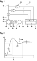
- Fig.1 shows a synchronous machine system 10 with a synchronous machine 12 and a voltage regulator 14.
- the synchronous machine 12 such as a synchronous generator and/or synchronous motor, is connected to an electrical grid 16 via its stator windings 18 and in particular the stator terminal 20.
- the stator windings are mounted to the stator 22 of the synchronous machine 12 and a rotor 24 of the synchronous machine 12 is rotatable mounted in the stator 20 and carries rotor windings 26, which are supplied by the voltage regulator 14.
- the rotor windings 26 may be supplied by an exciter system 28, which comprises exciter windings 30 rotating with the rotor 24 and supplied by static voltage regulator windings 32 electrically connected to the voltage regulator 14.
- a voltage from the voltage regulator 14 induces a voltage in the exciter windings 30, which is rectified with a exciter rectifier 34 and supplied to the rotor windings 26.
- the voltage regulator 14 comprises a converter 36, which is supplied via a transformer 38 connected to the electrical grid 16.
- a controller 40 which measures a terminal voltage y and a terminal current i in the terminals 20 of the synchronous machine 12 controls the converter 36.
- a synchronous generator 12 may contribute to an electrical power in the electrical grid 16 by transforming mechanical energy to electrical energy.
- the mechanical energy may be supplied by steam turbines, gas turbines or water turbines.
- the turbines may power the rotor 24 of the synchronous generator 12, which holds a magnetic field, which is generated by a current that flows through the rotor winding 26, such as a coil of wires attached to the rotor 24.
- a stable operation of the electrical grid 16 may require that the magnitude of the (usually three-phase) terminal voltage y of the synchronous generator 12 is almost constant and deviates only little from a given desired value.
- the terminal voltage y of a grid-connected generator 12 may non-locally depend on all other entities present in the electrical grid 16, such as electrical loads, renewable power sources, other generators, and may deviate substantially from its desired waveform.
- it may be necessary to regulate the magnitude and frequency of the terminal voltage y to a desired values by adequately adjusting the field current and rotor velocity, respectively.
- the current in the rotor windings 26 is provided by an exciter system 28, which may be seen as second generator 30, 32.
- the magnitude of the terminal voltage y of the synchronous generator 12 may be regulated through the manipulation of field current of the exciter system 28.
- the output of the voltage regulator 14 may be formed through a linear combination of the error, the integral of the error and derivative of the error.
- the constant coefficients k p , k i and k d of the linear combination may be called controller parameters or controller gains.
- the control parameters influence the performance of a closed-loop formed by the dynamical system comprising the voltage regulator 14, the synchronous machine 12 possibly including an exciter system 28.
- Fig. 2 shows a diagram with an example of the actual magnitude of the terminal voltage y m ( t ) during a step from an initial desired value r i to a final desired value r f under the control of the controller 40, which is usually called step response.
- Fig. 2 shows performance indices for the step response.
- the closed-loop reacts quickly to changes in the reference signal so that the actual magnitude of the terminal voltage y ( t ) approaches the new desired value r f as fast as possible.
- the rise time T r , the settling time T s , and the overshoot OS associated with a step response may be used as controller performance indices.
- the rise time T r may refer to the time interval in that the magnitude of the terminal voltage y ( t ) requires to increase from 10% to 90% of the reference step between the initial desired value r i and the final desired value r f .
- the form of the curve of terminal voltage y ( t ) with the settling time T s and the overshoot OS is typical for a second order system.
- the closed loop composed of the controller 40 and the synchronous machine 12 is a second order system for setting the control parameters of the controller 30 to achieve specific values of the settling time T s and the overshoot OS.
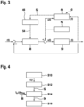
- Fig. 3 shows a block diagram with controller parts 42, 44, 44, 48 of the controller 40 and a block 50 illustrating the parts of the system 10, such as the synchronous machine 12 and the exciter system 28 reacting on the exciter signal u(t) of the controller 40.
- Fig. 4 shows a flow diagram for a method that may be performed by the controller parts 42, 44, 44, 48.
- step S10 the system comprising synchronous machine 12 and optionally the exciter system 28, is excited over a certain time interval [0, T ] and two time series of signals, the exciter signal u c , such as a voltage applied to the windings 32 or 26, and the magnitude of the terminal voltage y m , may be recorded with a certain sampling time h.
- the exciter signal u c such as a voltage applied to the windings 32 or 26, and the magnitude of the terminal voltage y m , may be recorded with a certain sampling time h.
- the excitation signal u may be generated by a signal generator 42 and/or may be either a step-signal or a pseudo-random binary signal.
- the signal generator 42 may generate a voltage to be applied to the rotor windings by generating the first time series of values of the excitation signal u and applying them to the synchronous machine 12.
- the excitation signal u c is generated by the controller 48, i.e. during operation of the synchronous machine 12.
- the second time series of may be determined by measuring the terminal voltage y m .
- the first time series of values of the excitation signal u and a second time series of measurement values of the terminal voltage y may then be received in the system identification block 40.
- step S12 the system identificator 44 determines coefficients 52 of a system transfer function G(s) of the system indicated by block 50.
- the system trans transfer function G(s) is a rational function in the Laplace variable s.
- G s b 0 s m + b 1 s m ⁇ 1 + ⁇ + b m s n + a 1 s n ⁇ 1 + ⁇ + a n , n ⁇ m
- the coefficients b 0 , ..., b m b 0 , ..., b m , a 1 , ..., a n (indicated as reference numeral 52 in Fig. 3 and 4 ) of the system transfer function G(s) are determined recursively with a regression analysis with instrumental variables based on the first time series as system input and the second time series as system output, as will be explained in the following.
- the model structure ( n, m ), i.e., the order of the numerator m and the order of the denominator n may vary.
- the structure may be fixed to (2,1).
- By increasing the denominator order it also may be possible to take the dynamics of a sensor into account in order to obtain a better fitting model.
- ( n, m ) may be be adapted to different situations, e.g. when the winding 26 of the synchronous machine 12 is energized by a static excitation system.
- the simply refined instrumental variable (SRIV) approach may be used to compute the coefficients 52, b 0 , ..., b m , a 1 , ..., a n of the system transfer function G(s) to model the small-signal behaviour of the system 50 comprising the synchronous machine 12 and possibly the exciter system 28.
- SRIV simply refined instrumental variable
- the basis of the computation is the data set u y where u and y are the discrete-time signals that map from a discrete interval ⁇ 1,2, ..., T ⁇ to the real numbers.
- y is the measured magnitude of the terminal voltage
- u is the voltage of the winding 26, 32 either of the synchronous machine 12 or of the exciter system 28.
- the constant h is the sampling time with which the signals are recorded.
- the data can be collected either by exciting the system by a reference step or by applying a pseudo-random binary signal to the field winding voltage.
- coefficient vector ⁇ a 1 , ... , a n , b 0 , ... , b m T and use u c and y c to denote the continuous-time signals obtained from a zero-order hold interpolation of the signals u and y , respectively.
- the parameters ⁇ are computed iteratively.
- An initial step excitation signal u f may be formed by filtering the first time series of measurement values of the excitation signal u with a high pass filter and/or an initial step terminal voltage yf may be formed by filtering the second time series of measurement values of the terminal voltage y with the high pass filter.
- initial step coefficients ⁇ 0 for the system transfer function G(s) may be obtained by minimizing the n th derivative of the initial step terminal voltage y f and a product of the coefficient vector ⁇ 0 and the regression vector ⁇ T , wherein the coefficient vector is formed of the initial step coefficients and regression vector is formed from derivatives of the initial step terminal voltage y and an initial step excitation signal u.
- the actual step excitation signal u f is calculated by filtering the previous step excitation signal u f with the denominator A of the system transfer function G(s) with actual step coefficients ⁇ k .
- the actual step terminal voltage y f is calculated by by filtering the previous step terminal voltage y f with the denominator A with the actual step coefficients ⁇ k .
- the second difference stems from the use of instrumental variables in the computation of the coefficient update.
- the actual step response x is calculated by filtering the first time series of measurement values u c of the excitation signal with the system transfer function G(s) with actual step coefficients ⁇ k .
- the next step coefficients ⁇ k +1 may be determined by minimizing a difference between a n th derivative of the actual step terminal voltage y f and a product of the coefficient vector ⁇ k and the instrumental variable vector ⁇ T .
- the instrumental variable vector ⁇ T is formed from derivatives of the actual step response x and the actual step excitation signal u f .
- the iteration may be repeated until
- the method is tuning free, i.e., given the data set ( u, y ), there are essentially no parameters that influence the outcome of the computation.
- the filter responses y f i , i ⁇ 1 , ... n are computed at once for all i ⁇ ⁇ 1, ... , n ⁇ by solving one initial value problem.
- a similar comment applies to u f j and x f i .
- u f j and x f i may have to be solved in the initial parameter computation and three initial value problems may have to be solved in each coefficient update iteration.
- a fourth order Runge-Kutta scheme with fixed step size may be used to solve the initial value problems.
- step S14 the parameter computer 46 uses the coefficients 52 of the model G(s) together with further specifications 56 used to determine the control parameters 54.
- a closed loop transfer function formed of a controller transfer function C(s) of the controller 48 and the system transfer function G(s) is compared with a desired closed loop transfer function, such as shown in Fig. 2 , to determine the controller parameters 54.
- the first controller is a so-called series/cascaded PID controller.
- the second controller is a double lead-lag controller.
- the specifications 56 to compute the parameters of the PID controller are a desired settling time T s and a desired overshoot OS (see Fig. 2 ).
- the control parameters T a , T b and K b may be used to set the factors k p , k i and k d for a proportional controller part, an integral control part and a differential controller part as described above.
- the closed-loop transfer function follows by V p K p s 2 T 1 T 2 ⁇ + sT 1 + V p K p .
- This closed-loop transfer function is compared with a second order transfer function (see Fi. 2), where the standard form of the second order transfer function may be provided by ⁇ 2 ⁇ 2 + 2 ⁇ s + s 2
- the specifications 56 to compute the control parameters 54 of a lead-lag controller 48 are a desired settling time T s , a desired overshoot OS and a desired steady state error e ss .
- the gain K R is chosen, so that desired steady state error e ss is enforced in the closed-loop, i.e., K R K p K R K p + 1 ⁇ e ss / 100 .
- T B 1 and T B 2 may be chosen to enforce the desired settling time and overshoot in the transfer function K R K p K R K p + s 1 + c T + s 2 cT 2
- the gain K R may be increased to ensure that c is real.
- the three-step procedure for steps S10, S12, S14 may be applied during the commissioning of the voltage regulator 14 to determine the controller parameters 54 and/or periodically to update the controller parameters 54, while the system 10 is in operation.
- the data in step S10 may be obtained by measuring the desired signals u , y while the system 10 is operating.
- control parameters 54 may be applied to the controller 48 of the voltage regulator 14.
- step S16 the controller 48 then may regulate the terminal voltage y towards a possibly time dependent reference signal r(t).
- the controller 48 may receive the reference signal r ( t ) and may control the magnitude of the terminal voltage y m ( t ) towards this reference signal r ( t ) .
Landscapes
- Engineering & Computer Science (AREA)
- Power Engineering (AREA)
- Physics & Mathematics (AREA)
- General Physics & Mathematics (AREA)
- Automation & Control Theory (AREA)
- Health & Medical Sciences (AREA)
- Artificial Intelligence (AREA)
- Computer Vision & Pattern Recognition (AREA)
- Evolutionary Computation (AREA)
- Medical Informatics (AREA)
- Software Systems (AREA)
- Control Of Eletrric Generators (AREA)
Priority Applications (1)
| Application Number | Priority Date | Filing Date | Title |
|---|---|---|---|
| EP25171892.0A EP4568101A3 (de) | 2019-06-06 | 2019-06-06 | Automatische bestimmung von steuerparametern für einen spannungsregler einer synchronmaschine |
Applications Claiming Priority (3)
| Application Number | Priority Date | Filing Date | Title |
|---|---|---|---|
| EP25171892.0A EP4568101A3 (de) | 2019-06-06 | 2019-06-06 | Automatische bestimmung von steuerparametern für einen spannungsregler einer synchronmaschine |
| EP19730137.7A EP3981067A1 (de) | 2019-06-06 | 2019-06-06 | Automatische bestimmung von steuerparametern für einen spannungsregler einer synchronmaschine |
| PCT/EP2019/064887 WO2020244769A1 (en) | 2019-06-06 | 2019-06-06 | Automatically determining control parameters for a voltage regulator of a synchronous machine |
Related Parent Applications (1)
| Application Number | Title | Priority Date | Filing Date |
|---|---|---|---|
| EP19730137.7A Division EP3981067A1 (de) | 2019-06-06 | 2019-06-06 | Automatische bestimmung von steuerparametern für einen spannungsregler einer synchronmaschine |
Publications (2)
| Publication Number | Publication Date |
|---|---|
| EP4568101A2 true EP4568101A2 (de) | 2025-06-11 |
| EP4568101A3 EP4568101A3 (de) | 2025-08-13 |
Family
ID=66826965
Family Applications (2)
| Application Number | Title | Priority Date | Filing Date |
|---|---|---|---|
| EP25171892.0A Pending EP4568101A3 (de) | 2019-06-06 | 2019-06-06 | Automatische bestimmung von steuerparametern für einen spannungsregler einer synchronmaschine |
| EP19730137.7A Ceased EP3981067A1 (de) | 2019-06-06 | 2019-06-06 | Automatische bestimmung von steuerparametern für einen spannungsregler einer synchronmaschine |
Family Applications After (1)
| Application Number | Title | Priority Date | Filing Date |
|---|---|---|---|
| EP19730137.7A Ceased EP3981067A1 (de) | 2019-06-06 | 2019-06-06 | Automatische bestimmung von steuerparametern für einen spannungsregler einer synchronmaschine |
Country Status (5)
| Country | Link |
|---|---|
| US (1) | US11689135B2 (de) |
| EP (2) | EP4568101A3 (de) |
| JP (1) | JP7293405B2 (de) |
| CN (1) | CN113966576B (de) |
| WO (1) | WO2020244769A1 (de) |
Families Citing this family (4)
| Publication number | Priority date | Publication date | Assignee | Title |
|---|---|---|---|---|
| CN115494723B (zh) * | 2022-09-06 | 2026-03-17 | 聚辰半导体股份有限公司 | 摄像头马达配置pid参数的控制工装、生产工站及方法 |
| CN115913037B (zh) * | 2022-10-12 | 2023-09-26 | 广州擎天实业有限公司 | 一种交流励磁系统的电流调节器的设计方法及装置 |
| CN119787299B (zh) * | 2024-11-19 | 2025-10-24 | 国网电力科学研究院有限公司 | 一种计及构网型新能源的频率紧急控制有效性边界估算方法、系统、设备及存储介质 |
| CN120930419B (zh) * | 2025-07-31 | 2026-03-31 | 江苏巨石数字技术有限公司 | 簧片式喷嘴挡板永磁型电气转换模块的结构参数优化方法 |
Citations (3)
| Publication number | Priority date | Publication date | Assignee | Title |
|---|---|---|---|---|
| EP0263616A2 (de) | 1986-10-09 | 1988-04-13 | International Control Automation Finance S.A. | Systeme und Verfahren zur Prozessregelung |
| US20020040250A1 (en) | 2000-08-21 | 2002-04-04 | Gaikwad Sujit V. | Auto-tuning controller using loop-shaping |
| WO2009097605A1 (en) | 2008-01-31 | 2009-08-06 | Basler Electric Company | Digital excitation control system for an electrical generator and an associated method of use |
Family Cites Families (10)
| Publication number | Priority date | Publication date | Assignee | Title |
|---|---|---|---|---|
| JPS63138402A (ja) * | 1986-12-01 | 1988-06-10 | Toshiba Corp | プロセス制御装置 |
| JPH0822306A (ja) * | 1994-07-08 | 1996-01-23 | Mitsubishi Heavy Ind Ltd | 演算制御パラメータ自動調整装置 |
| US6700356B1 (en) | 2000-10-24 | 2004-03-02 | Kohler Co. | Method and apparatus for regulating the excitation of an alternator of a genset |
| WO2004059400A1 (en) | 2002-12-27 | 2004-07-15 | Inea D.O.O. | Self-tuning controller for non-linear processes described by set of local linear models |
| DE102006035891B4 (de) * | 2006-07-31 | 2009-04-16 | Sew-Eurodrive Gmbh & Co. Kg | Antrieb, umfassend einen Elektromotor, der von einem Umrichter gespeist ist, und Verfahren zur Regelung des Motorstromes bei einem von einem Umrichter gespeisten Elektromotor |
| JP2009116515A (ja) * | 2007-11-05 | 2009-05-28 | Fuji Electric Systems Co Ltd | Pidパラメータ調節支援装置 |
| US20090195224A1 (en) | 2008-01-31 | 2009-08-06 | Basler Electric Company | Digital Excitation Control System Utilizing Self-Tuning PID Gains and an Associated Method of Use |
| FR2976747B1 (fr) * | 2011-06-15 | 2014-02-14 | Leroy Somer Moteurs | Alternateur a regulation de tension |
| EP2703914A1 (de) * | 2011-10-13 | 2014-03-05 | Institute of Nuclear Energy Research Atomic Energy Council | Hybrides Steuersystem und Verfahren für einen automatischen Spannungsregler |
| DE102012205540B4 (de) * | 2012-04-04 | 2023-08-17 | Vitesco Technologies GmbH | Verfahren und Vorrichtung zur sensorlosen Regelung einer fremderregten Synchronmaschine |
-
2019
- 2019-06-06 EP EP25171892.0A patent/EP4568101A3/de active Pending
- 2019-06-06 JP JP2021572464A patent/JP7293405B2/ja active Active
- 2019-06-06 WO PCT/EP2019/064887 patent/WO2020244769A1/en not_active Ceased
- 2019-06-06 EP EP19730137.7A patent/EP3981067A1/de not_active Ceased
- 2019-06-06 US US17/616,462 patent/US11689135B2/en active Active
- 2019-06-06 CN CN201980097156.7A patent/CN113966576B/zh active Active
Patent Citations (3)
| Publication number | Priority date | Publication date | Assignee | Title |
|---|---|---|---|---|
| EP0263616A2 (de) | 1986-10-09 | 1988-04-13 | International Control Automation Finance S.A. | Systeme und Verfahren zur Prozessregelung |
| US20020040250A1 (en) | 2000-08-21 | 2002-04-04 | Gaikwad Sujit V. | Auto-tuning controller using loop-shaping |
| WO2009097605A1 (en) | 2008-01-31 | 2009-08-06 | Basler Electric Company | Digital excitation control system for an electrical generator and an associated method of use |
Non-Patent Citations (1)
| Title |
|---|
| YOUNG P.: "The Instrumental Variable Method: A Practical Approach to Identification and System Parameter Estimation", IFAC SYMPOSIUM ON MODELLING AND CONTROL IN BIOMEDICAL SYSTEMS, vol. 18, no. 5, 1 July 1985 (1985-07-01), pages 1 - 15, XP093121085, DOI: 10.1016/S1474-6670(17)60535-4 |
Also Published As
| Publication number | Publication date |
|---|---|
| CN113966576A (zh) | 2022-01-21 |
| US11689135B2 (en) | 2023-06-27 |
| WO2020244769A1 (en) | 2020-12-10 |
| JP2022537918A (ja) | 2022-08-31 |
| EP3981067A1 (de) | 2022-04-13 |
| JP7293405B2 (ja) | 2023-06-19 |
| EP4568101A3 (de) | 2025-08-13 |
| CN113966576B (zh) | 2025-04-01 |
| US20220263445A1 (en) | 2022-08-18 |
Similar Documents
| Publication | Publication Date | Title |
|---|---|---|
| EP4568101A2 (de) | Automatische bestimmung von steuerparametern für einen spannungsregler einer synchronmaschine | |
| Cho et al. | Torque ripple-minimizing control of IPMSM with optimized current trajectory | |
| US9574511B2 (en) | System and method for a load anticipation feature and its tuning method for a generating set | |
| CN110476315A (zh) | 用于将电功率馈入供电网中的方法 | |
| Lenwari et al. | The use of genetic algorithms for the design of resonant compensators for active filters | |
| CN104052363A (zh) | 自动化电机控制 | |
| EP2961058A2 (de) | Auskoppelstromsteuerung mit direkter anlagenmodifikation in einem elektrischen servolenkungssystem | |
| WO2013102791A1 (en) | Method and apparatus for controlling a frequency converter | |
| Saleem et al. | Design of a fractional order PID controller with application to an induction motor drive | |
| US11522479B2 (en) | Method and system of subsynchronous oscillations and interactions damping | |
| CN102290809A (zh) | 用于控制功率生产实体的方法和系统 | |
| US12074534B2 (en) | Apparatus and methods for providing electrical converter control parameters based on the minimisation of the H-infinity norm | |
| EP3420632B1 (de) | System und verfahren für ein integriertes steuerungssystem für ein dieselgeneratoraggregat | |
| Mondal et al. | Robust observer design for sensorless voltage and frequency control of a doubly fed induction generator in standalone mode | |
| Amieur et al. | A new robust tilt-PID controller based upon an automatic selection of adjustable fractional weights for permanent magnet synchronous motor drive control | |
| CN105745834A (zh) | 用于机动车辆励磁旋转电机的数字调节器装置的比例积分调节回路 | |
| EP3002453B1 (de) | Automatische Einstellung von Parameterwerten eines Windparkreglers | |
| WO2021242337A1 (en) | System and method for automated tuning/configuring of a power system stabilizer (pss) in a digital excitation control system | |
| Gryning et al. | Stability boundaries for offshore wind park distributed voltage control | |
| US9960718B2 (en) | Control loop of a digital control device of a rotary electrical machine with excitation for a motor vehicle | |
| Mangera et al. | Automatic voltage regulator (AVR) controller design based on routh’s crution stability analysis in diesel-based power plants | |
| Gowrishankar et al. | MATLAB simulink model of fuzzy logic controller with PSS and its performance analysis | |
| Murari et al. | Electromagnetic Analysis of a DFIG‘s Controlled Operation Using Finite Elements Method | |
| Habbi et al. | Output voltage control of synchronous generator using Nelder–Mead algorithm based PI controller | |
| KR101635183B1 (ko) | 출력전류 평형을 위한 전류 응답성 조절 장치 및 방법 |
Legal Events
| Date | Code | Title | Description |
|---|---|---|---|
| PUAI | Public reference made under article 153(3) epc to a published international application that has entered the european phase |
Free format text: ORIGINAL CODE: 0009012 |
|
| STAA | Information on the status of an ep patent application or granted ep patent |
Free format text: STATUS: THE APPLICATION HAS BEEN PUBLISHED |
|
| STAA | Information on the status of an ep patent application or granted ep patent |
Free format text: STATUS: REQUEST FOR EXAMINATION WAS MADE |
|
| AC | Divisional application: reference to earlier application |
Ref document number: 3981067 Country of ref document: EP Kind code of ref document: P |
|
| AK | Designated contracting states |
Kind code of ref document: A2 Designated state(s): AL AT BE BG CH CY CZ DE DK EE ES FI FR GB GR HR HU IE IS IT LI LT LU LV MC MK MT NL NO PL PT RO RS SE SI SK SM TR |
|
| 17P | Request for examination filed |
Effective date: 20250514 |
|
| REG | Reference to a national code |
Ref country code: DE Ref legal event code: R079 Free format text: PREVIOUS MAIN CLASS: H02P0009100000 Ipc: H02P0009300000 |
|
| PUAL | Search report despatched |
Free format text: ORIGINAL CODE: 0009013 |
|
| AK | Designated contracting states |
Kind code of ref document: A3 Designated state(s): AL AT BE BG CH CY CZ DE DK EE ES FI FR GB GR HR HU IE IS IT LI LT LU LV MC MK MT NL NO PL PT RO RS SE SI SK SM TR |
|
| RIC1 | Information provided on ipc code assigned before grant |
Ipc: H02P 9/30 20060101AFI20250708BHEP Ipc: H02P 25/03 20160101ALI20250708BHEP Ipc: G05B 11/42 20060101ALI20250708BHEP Ipc: G05B 13/04 20060101ALI20250708BHEP Ipc: H02P 9/10 20060101ALI20250708BHEP Ipc: H02P 23/14 20060101ALI20250708BHEP |