EP4568171A1 - Procédé de génération de clé quantique de plusieurs récepteurs - Google Patents
Procédé de génération de clé quantique de plusieurs récepteurs Download PDFInfo
- Publication number
- EP4568171A1 EP4568171A1 EP24217039.7A EP24217039A EP4568171A1 EP 4568171 A1 EP4568171 A1 EP 4568171A1 EP 24217039 A EP24217039 A EP 24217039A EP 4568171 A1 EP4568171 A1 EP 4568171A1
- Authority
- EP
- European Patent Office
- Prior art keywords
- receivers
- key generation
- connections
- quantum key
- time period
- Prior art date
- Legal status (The legal status is an assumption and is not a legal conclusion. Google has not performed a legal analysis and makes no representation as to the accuracy of the status listed.)
- Granted
Links
Images




Classifications
-
- H—ELECTRICITY
- H04—ELECTRIC COMMUNICATION TECHNIQUE
- H04L—TRANSMISSION OF DIGITAL INFORMATION, e.g. TELEGRAPHIC COMMUNICATION
- H04L9/00—Cryptographic mechanisms or cryptographic arrangements for secret or secure communications; Network security protocols
- H04L9/08—Key distribution or management, e.g. generation, sharing or updating, of cryptographic keys or passwords
- H04L9/0816—Key establishment, i.e. cryptographic processes or cryptographic protocols whereby a shared secret becomes available to two or more parties, for subsequent use
- H04L9/0852—Quantum cryptography
- H04L9/0858—Details about key distillation or coding, e.g. reconciliation, error correction, privacy amplification, polarisation coding or phase coding
-
- H—ELECTRICITY
- H04—ELECTRIC COMMUNICATION TECHNIQUE
- H04B—TRANSMISSION
- H04B10/00—Transmission systems employing electromagnetic waves other than radio-waves, e.g. infrared, visible or ultraviolet light, or employing corpuscular radiation, e.g. quantum communication
- H04B10/70—Photonic quantum communication
Definitions
- the invention relates to a method for quantum key generation between at least four receivers according to the features of the preamble of claim 1 and to a system for quantum key generation between at least four receivers according to the features of the preamble of claim 15.
- Networks for quantum key generation using entangled photon pairs are known.
- several receivers are connected to each other, for example, via a source.
- the number of physical connections, i.e., quantum channels between the receivers increases only by the relation i ( i - 1)/2, where i is the number of receivers.
- i is the number of receivers.
- networks with a direct connection between all receivers a large number of additional quantum channels are necessary.
- Quantum keys can be generated between all receivers based on the entangled photon pairs.
- connection between the two receivers of the entangled photon pairs must be aligned with respect to the selected entanglement property.
- This entanglement property can, for example, represent the polarization, time, and/or mode of the photons.
- the alignment of the connection is achieved, for example, in a fiber, via a polarization control.
- the present invention is based on the object of providing an improved, more efficient, faster and more robust method for quantum key generation between at least four receivers and a corresponding device.
- the object is achieved according to the invention by a method for quantum key generation between at least four receivers according to the features of claim 1.
- steps i) to iii) are carried out in each time period, and that in each time period, before and/or during step ii), a comparison of the entanglement property is carried out only between two or more connections V j , which can be compared independently of one another in order to enable quantum key generation in these two or more connections V j , and that the time periods differ in such a way that at least one connection V j is exchanged for another connection V j in which quantum key generation was not yet possible in order to carry out quantum key generation between all receivers over the several time periods, and/or that in the last time period, a connection V , or several of the connections V j , or all of the connections V j , that were already formed in previous time periods are repeated in order to perform a new quantum key generation.
- the object is achieved according to the invention by a system for quantum key generation with entangled photon pairs between at least four receivers according to the features of claim 15.
- An advantage of the method and system according to the invention is that, through the temporal rotation of the alignment and thus for quantum key generation, a pool of quantum keys is generated between all receivers in the time periods. After passing through the multiple time periods, all receivers are served with entangled photon pairs, whereby, according to the invention, each connection has been aligned at least once between each receiver in at least one time period for quantum key generation.
- quantum keys are generated at all receivers by rotating the connections V j so that after the several time periods each receiver has generated a quantum key with every other receiver.
- the advantage here is that by adjusting the entanglement properties only between independent connections in each time period, the method and the system are optimized in such a way that the inventive temporal division of the adjustment results in a better generation rate for quantum key generation between all receivers.
- the improved generation rate is achieved because the inventive method and the inventive system allow the connections V j to be adjusted more precisely and quickly. This is because, according to the invention, several, but always independent, connections V j are adjusted simultaneously, thus preventing mutual interference during the adjustment.
- a faster reconciliation can preferably be performed in the last time period by using the known reconciliation values of the previous connections V j as initial values for the reconciliation.
- the quantum key generation according to the invention can be carried out more quickly and thus environmental effects, such as temperature fluctuations or vibrations, can be compensated for more precisely and quickly, since the adjustments do not Due to the lack of mutual interference during the alignment of the multiple connections V j , no iterative alignment steps between multiple connections V j are necessary.
- the system according to the invention can be provided cost-effectively since fewer adjustment devices are necessary, since only one adjustment device is required for each connection V j .
- a further advantage of the method and network according to the invention is the direct connection of the source to each receiver via a quantum channel. This increases the number of physical connections, i.e., quantum channels, only by the ratio i ( i - 1)/2. In contrast, a network with direct connections between the individual receivers would require a large number of additional quantum channels.
- a further advantage of the method and network according to the invention is that the last time period can be used to repeat a connection V j , or several of the connections V j , or all connections V j , that were already formed in previous time periods. This makes it possible to generate multiple quantum keys in a single pass. Preferably, after the multiple time periods have been completely run through, at least two quantum keys can be generated for each connection V j . This enables rapid generation of multiple quantum keys.
- the method and system for quantum key generation comprise at least four receivers, preferably i receivers E p with the number i equal to a natural number equal to or greater than 4 and with the numbering p equal to a natural number.
- connection V j Two receivers E p of an entangled photon pair form a connection V j with the number j equal to a natural number.
- s connections V j are possible between all receivers, with s ⁇ i i ⁇ 1 2 .
- r connections V j are compared, with the number r equal to a natural number greater than 2 and less than s .
- the method and system for quantum key generation use multiple time periods t k , preferably q time periods t k , with the number q equal to or greater than 2 and with the numbering k equal to a natural number. This means that within the multiple, preferably q, time periods t k , a quantum key generation is performed between all recipients. Performing a quantum key generation with the q time periods t k can also be referred to as a complete rotation.
- the method and the system according to the invention result in an improved temporal efficiency factor for generating quantum keys with s q > 1
- the temporal efficiency factor describes the increase in generation rate compared to a method and a system in which a quantum key is always generated only between two receivers.
- a comparison with a method and a system in which all connections are verified simultaneously differs significantly depending on the respective quality of the verification between all connections.
- the method and the system according to the invention thus reduce the number q of time periods t k required for a number s of connections V j .
- At least four receivers preferably between i receivers E p with i equal to a natural number equal to or greater than 4 and with p equal to a natural number, means that the quantum key generation is carried out between four receivers, or five receivers, or six receivers, or seven receivers or more receivers.
- Quantum key generation between all of the at least four receivers means that each receiver generates a quantum key with each other receiver. For example, with four receivers, a quantum key is generated between the first receiver E 1 and the second receiver E 2 , between the first receiver E 1 and the third receiver E 3 , between the first receiver E 1 and the fourth receiver E 4 , between the second receiver E 2 and the third receiver E 3 , between the second receiver E 2 and the fourth receiver E 4 , and between the third receiver E 3 and the fourth receiver E 4 .
- quantum key generation between all of the at least four receivers means that a quantum key is generated between these at least four receivers.
- Additional receivers in the system may be connected to the source that do not generate a quantum key at the time of quantum key generation between the four receivers, but are also participating receivers in a subsequent quantum key generation.
- the generation of multiple entangled photon pairs in the source and in step i) means that multiple entangled photon pairs can be generated simultaneously and/or sequentially in the source. Simultaneously means that multiple entangled photon pairs are generated at the same or approximately the same time, with the wavelengths of these entangled photon pairs differing from one another. Sequentially means that multiple entangled photon pairs can be generated sequentially in time, with these photon pairs being able to have the same wavelength or different wavelengths. By generating entangled photon pairs with the same wavelength sequentially in time, the length of the quantum key between two specific receivers is increased. Entangled photon pairs with different wavelengths enable quantum key generation between multiple different receivers of the multiple connections V j .
- steps ii), iii) and iv) whereby in step ii) several signal photons and idler photons from different entangled photon pairs are simultaneously and/or successively divided between the quantum channels and transmitted into them, and in step iii) the photons are simultaneously detected at several receivers or successively at one or more receivers, and in step iv) several quantum keys are simultaneously and/or successively generated between several receivers.
- Methods for quantum key generation with entangled photon pairs mean that steps i), ii) and iii) are carried out successively for one entangled photon pair at a time, but steps i), ii) and iii) can also be carried out simultaneously for several photon pairs with different wavelengths.
- Alignment of the entanglement property means that the reference system of the entanglement property used to measure a photon pair in the Detection module used in the detection in step iii) is matched to each other at the two corresponding receivers before and/or during step ii).
- the polarization of the respective detection modules is matched to each other by transmission via the corresponding connection V j as a reference system, whereby any polarization rotation can be compensated for by so-called polarization controllers, for example by transmitting the photons in fibers or arranging the elements of the system.
- a laser beam with a defined polarization in one basis is transmitted to a second receiver at a first receiver and the polarization of the laser beam in this basis is measured at the second receiver.
- the quantum channel in the first basis can be matched, for example, by minimizing the laser beam at the second receiver during a measurement in vertical polarization.
- This minimization is carried out in a further step for a second basis which is orthogonal to the first basis, for example for the +/- 45° horizontally polarized laser beam.
- connections V j are aligned for which an independent alignment is possible, i.e. which do not interfere with or influence each other. This allows the alignment to be carried out much more precisely and quickly, which leads to a higher generation rate of the quantum key. Only between two or more connections V j means that at least two connections V j and a maximum of all other possible connections V j that can be aligned independently of one another are aligned in a time period.
- connection V j Independently calibrating the connection V j over a time period t k means that the tuning of the reference frames of the receivers and the connections V j does not interfere with or influence each other during this time period t k . This can significantly improve the quality of photon transmission and detection, leading to a higher quantum key generation rate.
- the connection V 1 between the first receiver E 1 and the second receiver E 2 can be calibrated independently of the connection V 2 between the third receiver E 3 and the fourth receiver E 4 .
- connection V 1 between the first receiver E 1 and the second receiver E 2 can be calibrated independently of the connection V 2 between the first receiver E 1 and the third receiver E 3 if the calibrating of the connection V 1 takes place at the second receiver E 2 and the calibrating of the connection V 2 takes place at the third receiver E 3 , whereby, in contrast, a calibrating of the connection V 1 at the second receiver E 2 and the calibrating of the connection V 2 at the first receiver E 1 would disturb the calibrating of the connection V 1 .
- Exchanging at least one connection V j with another connection V j + x means that only one connection V j of the previous time period t k is exchanged and replaced by a connection V j + x in which quantum key generation was not yet possible, or that two connections V j , V j +1 of the previous time period t k are exchanged and replaced by two connections V j + x 1 , V j + x2 in which quantum key generation was not yet possible, and so on for three, four and more connections, or that all connections of the previous time period t k are exchanged and replaced by the corresponding number of connections in which quantum key generation was not yet possible.
- a connection V j in which quantum key generation was not yet possible means that steps i) to iii) have not yet been completed for this connection V j , while this connection V j was independently calibrated before and/or during step ii). This means that, for the purposes of the method and system described here, quantum key generation between two receivers is only possible if the corresponding connection V j was and/or is calibrated before and/or during the transmission of the photons in step ii). If calibrating is not carried out, photons can still be measured, but the different reference systems of the receivers cannot generate a common key.
- To perform a quantum key generation between all receivers through the multiple time periods t k means that after the multiple time periods t k , steps i), ii), iii) and iv) have been carried out for all possible connections between all receivers and that a comparison has been carried out for all connections V j before and/or during step ii) in at least one time period t k .
- the multiple time periods are repeated several times, preferably consecutively, preferably a second time, a third time, or a fourth time, or more often. This means that a complete rotation is repeated consecutively. This allows quantum keys to be generated between all recipients over a longer period of time.
- the time periods t k are carried out sequentially for the quantum key generation. This means that the time periods t k are carried out directly consecutively for the quantum key generation. are formed. “Directly consecutive” means that no other connections are served between them. “Directly consecutive” also means that no connections V j are served between the time periods t k in a time window, for example, to perform maintenance work. This advantageously results in a simple generation of the quantum keys between all receivers.
- the time periods t k are not carried out sequentially for quantum key generation. This means that the time periods t k are not formed directly one after the other for quantum key generation.
- Other connections can therefore be served between two time periods t k .
- Other connections can be understood to mean one or more connections V j from one of the several time periods t k , or several connections that cannot be synchronized independently of one another.
- Non-sequential implementation advantageously results in certain connections V j being able to be served multiple times, for example if there is an increased demand for quantum keys between two specific receptions.
- Connections V j that can also be synchronized independently also advantageously result in higher quality and generation rate.
- one of the time periods t k can be repeated or a new time period can be inserted in which connections V j are served that can be synchronized independently of one another. If necessary, connections between two time periods can also be served which cannot be adjusted independently of each other, whereby in these connections an increased adjustment requirement or a worse generation rate results.
- the entangled photon pairs are generated by a non-linear process, preferably by parametric fluorescence (down-conversion), spontaneous parametric fluorescence (spontaneous parametric down-conversion), or four-wave mixing.
- the source has one or more non-linear crystals which are designed to generate entangled photon pairs by a non-linear process, preferably by parametric fluorescence (down-conversion), spontaneous parametric fluorescence (spontaneous parametric down-conversion), or four-wave mixing.
- the entangled photon pairs can be entangled in time, and/or polarization, and/or orbital angular momentum, and/or spin angular momentum.
- the advantage of using time-entangled photon pairs is robust entanglement.
- the advantage of using polarization-entangled photon pairs is their ease of generation and alignment, as well as the potential for automation of the alignment.
- the advantage of using orbital angular momentum and/or spin angular momentum entangled photon pairs is the high dimensions that are possible for the photon pairs.
- the alignment device for polarization-entangled photon pairs comprises one or more wavelength plates, and/or fiber squeezers, and/or polarization controllers, and/or liquid crystals.
- the multiple components can also be combined with one another, thereby enabling even more precise Adjustment is possible.
- the advantage of this type of design lies in the easily controllable adjustment, which can also be automated, and the cost-effective components.
- a time period in the connection V j is adjusted.
- the adjustment device for time-entangled photon pairs comprises one or more optical delay devices. The advantage of such a design lies in the very precise and simple control of the adjustment.
- the alignment device for photon pairs entangled in orbital angular momentum and/or spin angular momentum comprises one or more wavelength plates and/or a spatial light modulator (SLM).
- SLM spatial light modulator
- each receiver or each quantum channel of a receiver has a matching device.
- the system may have only i - 1 balancing devices. This allows for a cost-effective system to be provided.
- the adjustment for each connection V j before and/or during step ii) is carried out only by one adjustment device, arranged at one of the two receivers or in one of the two quantum channels.
- the arrangement of the source, the receivers and the quantum channels means that in such a configuration the adjustment of the entire connection V j can be carried out by a single adjustment device which is arranged somewhere between the two receivers. This simplifies the adjustment process.
- An adjustment device which is arranged directly at the respective receiver is particularly protected against external influences, i.e. attempted manipulation and interference, since no additional communication between the receiver and the adjustment device via public channels is necessary for adjustment.
- the adjustment is carried out, monitored and/or regulated before and/or in step ii) by a control device which is connected to all adjustment devices. It can be provided that the control device is arranged at one of the receivers. It can be provided that the control device is designed as a computer or integrated circuit (IC), preferably as an FPGA element (Field Programmable Gate Array). It can be provided that the computer or integrated circuit (IC), preferably as an FPGA element (Field Programmable Gate Array), comprises a storage medium which contains instructions which, when executed by the computer or integrated circuit (IC), preferably as an FPGA element (Field Programmable Gate Array), cause it to carry out the adjustment before and/or during step ii). Such a design advantageously results in a possible automation of the method.
- step i) entangled photon pairs are generated with wavelengths that are randomly distributed over a broad spectrum, or that specifically entangled photon pairs with certain wavelengths are generated. It can be provided that in step i) entangled photon pairs are generated in each time period t k for all possible connections V j , or that in step i) entangled photon pairs are generated in each time period t k only for the connections V j that are also matched therein.
- the advantage of generating photons in a broad spectrum is the cost-effective provision of the entangled photon pairs to a large number of receivers.
- the advantage of generating photons with specific wavelengths is that for each connection V j , photons can be specifically generated for these connections V j in the corresponding time period t k , thereby increasing the generation rate for quantum key generation.
- the photons generated in step i) are generated in a spectrally separate signal wavelength range and idler wavelength range.
- “Spectrally separate” here means that the wavelengths of the signal photon and the idler photon of the pairs differ, and that the wavelengths of the pairs differ. This results in the advantage of a simpler and lower-loss splitting of the photons in step ii).
- the photon pairs generated in step i) are spectrally separated from each other for each connection V j .
- Spectrally separated entangled photon pairs mean that, on the one hand, the signal and idler photons of a photon pair have different wavelengths, ie, ⁇ sx ⁇ ⁇ ix . This is also referred to as non-degenerate (non-degenerated) photon pair.
- the wavelengths of the signal photons of the photon pairs differ spectrally from one another, i.e. ⁇ sx ⁇ ⁇ s ( x +1) .
- the idler photons i.e. the wavelengths of the idler photons differ spectrally from one another, i.e. ⁇ ix ⁇ ⁇ i ( x +1) . It is important that several of the spectrally separated photon pairs can be generated one after the other in order to generate a longer quantum key.
- the frequency multiplexer is designed to carry out the division of the signal photons and the idler photons in step ii).
- assigning the signal and idler photons to the quantum channels based on their wavelength in step ii) and by the frequency multiplexer means that the source generates signal and idler photons with different wavelengths and transmits the photons, preferably in a spatial mode, to the frequency multiplexer.
- the frequency multiplexer divides the signal and idler photons into the different quantum channels according to their wavelength.
- Fiber optic links mean that not all transmission takes place via a single fiber optic cable, but that free-space links are also possible over certain sections.
- the advantage of this configuration lies in the cost-effective and simple construction of the network.
- each The detection module has one or more detectors and a measurement module. Using the measurement module and the detectors, the entanglement properties of the photons for quantum key generation, as well as the time of photon detection, can be determined.
- the at least one detector or the plurality of detectors are designed as single-photon detectors, preferably as germanium or silicon detectors, or single-photon avalanche diodes or indium gallium arsenite detectors, or superconducting nanowire single-photon detectors, or silicon avalanche photodiodes.
- the measuring module has a polarizer, and/or an asymmetric interferometer, and/or a spatial light modulator (SLM).
- a polarizer and/or an asymmetric interferometer, and/or a spatial light modulator (SLM).
- SLM spatial light modulator
- the receiver has multiple detection modules. It can be provided that the multiple detection modules of a receiver detect photons in different wavelength ranges. It can be provided that in step iii) one or more receivers simultaneously detect multiple signal photons and/or idler photons with different wavelengths. This allows the receiver to simultaneously generate quantum keys with multiple other receivers, since photons with different wavelengths can be detected simultaneously. It can be provided that frequency filters are arranged in front of the multiple detection modules in order to enable quantum key generation with multiple receivers simultaneously by dividing the photons among the detection modules based on their wavelength. This allows a respective partner receiver to be assigned to each detection module of a receiver. It can be provided that the frequency filter is designed as a dichroic mirror, a grating, or a filter.
- a raw key is generated at both receivers from the detected photons in step iii) for quantum key generation. It can also be provided that after the raw key has been generated, the raw key is sifted. For sifting, information is exchanged between the two receivers after the photons have been measured. This information could be, for example, the timestamps of the measured photons. Each receiver then carries out the sifting process on its own raw key. It can be provided that after sifting, additional steps such as error detection and/or error correction and/or privacy amplification are carried out. Through the sifting and any further steps, a common key can be generated at both receivers through quantum key generation.
- a transmission rate of entangled photons between two or more receivers of at least 1 kHz, preferably at least 100 kHz, most preferably at least 10 MHz.
- step iv) for the connections of a time period t k takes place during and/or after the corresponding time period t k .
- steps i) to iv) are carried out in each time period.
- steps i) to iii) are carried out in each time period, and step iv) takes place after the respective time period.
- the generation of the quantum key from the raw key can also start during the respective time period and only be completed in a subsequent time period. It is essential that the detection of the photons in step iii) can already generate a raw key for the quantum key generation, which is used to generate the common key is used.
- step iv) enables complete quantum key generation within the respective time period, whereby a quantum key can be generated from the photons already detected while further photons are being generated.
- the transmission in step ii) takes place via a splitter and/or a switch in the quantum channel.
- two or more receivers are connected to the source via a splitter and/or a switch via a common quantum channel. It is essential that in such a configuration, these two or more receivers, which are connected to the source via a splitter and/or a switch via a common quantum channel, cannot generate a quantum key among themselves.
- quantum key generation between all receivers means that each of these two or more receivers, which are connected to the source via a splitter and/or a switch via a common quantum channel, can generate quantum keys with all other receivers, but not with the receiver, which also receives photons via the splitter and/or switch.
- a splitter can, for example, be designed as a beam splitter that randomly distributes the photons to one of its output channels.
- a switch can, for example, be designed as a movable mirror or a pluggable connection, whereby the photons are directed to one of the output channels depending on the position of the mirror or the plugged connection.
- the splitters and/or switches can represent an access node or service node, relay nodes, or a user node.
- QAN QKD access network
- QBN QKD backbone network
- steps i) to iii) are carried out with the comparison, preferably steps i) to iv).
- steps i) to iii) are carried out with the comparison, preferably steps i) to iv).
- steps i) to iii are carried out with the comparison, or for three connections V j , steps i) to iii), preferably steps i) to iv), are carried out with the comparison, or for four connections V j , steps i) to iii), preferably steps i) to iv), are carried out with the comparison, and so on.
- the more connections V j that are compared in each time period t k the higher the generation rate of the quantum keys for all recipients.
- a receiver is included at most once in the connections V j of the respective time period t k . This provides a simple way to ensure that the alignment of the connections V j of this time period t k is carried out independently of one another.
- a receiver in each time period t k , a receiver is included in several of the connections V j of the respective time period t k .
- one of the receivers is included in several of the connections V j of the respective time period t k . It is essential that the comparison of all connections V j of this time period t k continues to be carried out independently of one another. This means that a receiver with a high communication requirement can be served multiple times with a higher quantum key generation rate.
- each time period t k one of the receivers is included in all connections of the respective time period, and/or that in different time periods t k a different one of the receivers is included in all connections of the respective time period, and/or that in a time period t k + 1 at least one connection V j of the time period t k is included, where k is a natural number, and/or that in each time period t k + 1 at least one connection V j of the time period t k is included, where k is a natural number.
- individual connections or several connections or all connections can be traversed twice, for example, and thus used twice or multiple times for quantum key generation.
- the number of time periods is equal to or greater than the number of recipients.
- each time period t k is at least 1 s, preferably at least 1 min, preferably at least 5 min or more. It can be provided that the length of the time periods t k differs from one another. This advantageously results in the time periods t k being able to be adapted to the respective requirements for connections V j that have a higher or lower key requirement.
- receivers E 1 , E 2 etc. are referred to as receivers A, B etc.
- a quantum key generation method and a quantum key generation system with four receivers are presented here.
- all receivers perform quantum key generation among themselves.
- the time periods t 2 and t 3 are to be read in the same way.
- steps i) to iii), preferably i) to iv), can be carried out simultaneously for two compounds, while at the same time the These connections can be aligned without mutual interference, thus ensuring a high transmission rate and quality.
- a quantum key generation method and a quantum key generation system with four receivers are presented here. In this system, all receivers perform quantum key generation among themselves.
- a quantum key generation method and a quantum key generation system with five receivers are presented here. In this system, all receivers perform quantum key generation among themselves.
- a longer quantum key can be generated if there is an increased demand for this one or more connections.
- the non-exclusive third example described in this way shows a sequential implementation for quantum key generation.
- the second time period t 2 is performed a second time. This is advantageous when there is a high demand for quantum keys between receivers B and C and receivers D and E.
- the connections BC and AD are served in a time period t 6. This is advantageous if there is a high demand for quantum keys between the receivers B and C and the receivers A and D.
- a quantum key generation method and a quantum key generation system with five receivers are presented here.
- all receivers perform quantum key generation among themselves.
- This fourth example is the extension of the previously described second example with four receivers by one receiver, thus with five receivers.
- this method can be applied to several receivers according to the second or fourth example. Expand the number of recipients. Specifically, to 6 recipients, or to 7 recipients, or to 8 or more recipients.
- a quantum key generation method and a quantum key generation system with six receivers are presented here. In this system, all receivers perform quantum key generation among themselves.
- connections V j into the time periods are also possible, and that it is also possible to divide the connections into more than five time periods, whereby one or more connections are contained in several time periods.
- a quantum key generation method and a quantum key generation system with seven receivers are presented here. In this system, all receivers perform quantum key generation among themselves.
- connections V j into the time periods are also possible, and that it is also possible to divide the connections into more than seven time periods, whereby one or more connections are contained in several time periods.
- a quantum key generation method and a quantum key generation system with eight receivers (A, B, C, D, E, F, G, H). In this system, all receivers generate quantum keys among themselves.
- connections V j into the time periods are also possible, and that it is also possible to divide the connections into more than eight time periods, whereby one or more connections are contained in several time periods.
- a method and system for quantum key generation with four receivers (A 1 , A 2 , B 1 , B 2 ) is presented here.
- all A i receivers can perform quantum key generation with all B i receivers.
- quantum key generation between the two receivers A 1 and A 2 and between the two receivers B 1 and B 2 is not possible.
- a method and system for quantum key generation with five receivers (A 1 , A 2 , A 3 , B 1 , B 2 ) is presented here.
- all A i receivers can perform quantum key generation with all B i receivers.
- Quantum key generation between the receivers A 1 , A 2 , and A 3 , as well as between the two receivers B 1 and B 2 is not possible.
- the alignment of the entanglement property can be performed solely by the receivers with the larger number, i.e., in this case, by the A i receivers.
- the B i receivers do not necessarily need to be equipped with a device for adjusting the entanglement property.
- Fig. 1 shows a schematic representation of a first embodiment of a system 1 according to the invention for quantum key generation with entangled photon pairs between four receivers A, B, C and D.
- the system 1 for quantum key generation from Fig. 1 has a source 2 configured to generate entangled photon pairs with an entanglement property.
- a frequency multiplexer 3 is arranged in the source 2, which is configured to divide the signal photons and idler photons of the entangled photon pairs into the quantum channels 5 of the plurality of receivers 4 based on their wavelength.
- the receivers 4 A, B, and C each have an adjustment device 8.
- the receiver 4 D also has an adjustment device 8, as shown in dashed lines.
- the adjustment devices 8 adjust the reference systems with respect to the entanglement properties of the various receivers 4.
- Fig. 2 shows the inventive system 1 for quantum key generation from Fig. 1 , where Fig. 2 For a better overview, the adjustment devices 8 are not shown. In Fig. 2 the possible connections V j between the receivers 4 for quantum key generation and their division into the several time periods t k are shown.
- a first time period t 1 in this embodiment, the quantum key generation is carried out between the receivers A and C and the receivers B and D, as in Fig. 2 indicated by the dashed arrows.
- entangled photon pairs are generated in source 2 and transmitted to all receivers, with the connections via quantum channels 5 between receivers A and C and between receivers B and D being calibrated during this first time period t 1.
- the calibrating can be performed during this first time period t 1 , for example, by a calibrating device 8 at receiver A and receiver B.
- a second time period t 2 in this embodiment, the quantum key generation is carried out between the receivers A and B and the receivers C and D, as in Fig. 2 indicated by the dotted arrows.
- the alignment of the connections can be carried out in this second time period t 2 , for example, by a matching device 8 at receiver A and at receiver C.
- a third time period t 3 in this embodiment, the quantum key generation is carried out between the receivers A and D and the receivers C and B, as in Fig. 2 indicated by the dash-dot arrows.
- the alignment of the connections can be carried out in this second time period t 3 , for example, by a matching device 8 at receiver A and at receiver C.
- Fig. 3 shows a schematic representation of a second embodiment of a system 1 according to the invention for quantum key generation with entangled photon pairs between six receivers A, B, C, D, E and F.
- the system 1 for quantum key generation comprises a source 2, which is designed to generate entangled photon pairs in an entanglement property.
- a frequency multiplexer 3 is arranged in the source 2, which is designed to separate the signal photons and idler photons of the entangled photon pairs to be distributed among the quantum channels 5 of the multiple receivers 4 based on their wavelength.
- the receivers 4 A, B, C, D, and E each have an adjustment device 8.
- the receiver 4 F also has an adjustment device 8, as shown in dashed lines.
- the adjustment devices 8 adjust the reference systems with respect to the entanglement properties of the various receivers 4.
- Fig. 4 shows a schematic representation of a third embodiment of a system 1 according to the invention for quantum key generation with entangled photon pairs between four receivers A 1, A 2 , B 1 and B 2.
- the receivers A 1 and A 2 (or B 1 and B 2 ) are each connected to a splitter 6 via their own quantum channel 5 and, via this, to a common quantum channel 5 with the source 2. It is essential that in this embodiment the two receivers 4 A 1 and A 2 (or B 1 and B 2 ), which are connected to the source 2 via a splitter 6 via a common quantum channel 5, cannot generate a quantum key among themselves.
- quantum key generation between all receivers 4 means that each of these two receivers A 1 and A 2 (or B 1 and B 2 ), which are connected to the source 2 via a splitter 6 via a common quantum channel 5, can generate quantum keys with all other receivers 4 B 1 and B 2 (or A 1 and A 2 ), but not with each other.
- the receivers 4 A 1 and A 2 each have an adjustment device 8.
- the receivers 4 B 1 and B 2 have an adjustment device 8, as shown in dashed lines.
- the adjustment devices 8 adjust the reference systems with respect to the entanglement properties of the various receivers 4.
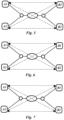
- FIGs. 5, 6 and 7 The system 1 according to the invention for quantum key generation is Fig. 4 shown, where in the Figs. 5, 6 and 7 For a better overview, the adjustment devices 8 are not shown.
- Figs. 5, 6 and 7 show the possible connections between the receivers 4 for quantum key generation and their division into the several time periods t k .
- FIG. 5 A first possible classification of the connections is shown, in which, in a first time period t 1 , a quantum key is generated between the receivers A 1 and B 2 and the receivers A 2 and B 2 (dashed arrows), with the connection being verified. In a second time period t 2 , a quantum key is generated between the receivers A 1 and B 1 and the receivers A 2 and B 1 (dotted arrows), with the connection being verified.
- FIG. 6 A second possible classification of the connections is shown, in which in a first time period t 1 a quantum key generation takes place between the receivers A 2 and B 1 and the receivers A 2 and B 2 (dashed arrows) with comparison of the connection. In a second time period t 2 a quantum key generation takes place between the receivers A 1 and B 1 and the receivers A 1 and B 2 (dotted arrows) with comparison of the connection.
- the difference to the connections of Fig. 5 lies in the fact that for Fig. 5 the adjustment devices 8 at the receivers A 1 and A 2 are sufficient, and for Fig. 6 the adjustment devices 8 can be arranged at the receivers B 1 and B 2 .
- FIG. 7 A third possible classification of the connections is shown, in which in a first time period t 1 a quantum key generation takes place between the receivers A 1 and B 2 and the receivers A 2 and B 1 (dashed arrows) with comparison of the connection. In a second time period t 2 a Quantum key generation between receivers A 1 and B 1 and receivers A 2 and B 2 (dotted arrows) with connection verification.
- Figs. 8 and 9 show two further embodiments of the system 1 according to the invention for quantum key generation with six receivers 4.
- the source 2 is connected to the six receivers 4 via several quantum channels 5, splitters 6 and switches 7.
- the Figures 8 and 9 only in that in Fig. 8 the receivers A1, A2, A3 and A4 are first connected to the source 2 via a splitter 6 and then further split by two switches 7 and in Fig. 9 the receivers A1, A2, A3 and A4 are first connected to the source 2 via a switch 7 and then further split by two splitters 6.
- the quantum key generation is carried out in both embodiments analogously to the embodiment of the Fig. 4 to 7 .
- Fig. 10 shows the system 1 for quantum key generation from the embodiment of the Fig. 1 , where Fig. 10 Additionally, the control device 9 (key management system) is shown. In this embodiment, the control device 9 is connected to the adjustment devices 8 via lines and the respective receiver 4.
- the control device 9 key management system
- Fig. 11 shows the system 1 for quantum key generation from the embodiment of the Fig. 4 where in Fig. 11 Additionally, the control device 9 is shown.
- the control device 9 key management system
- the control device 9 is connected to the adjustment devices 8 via lines and the respective receiver 4.
Landscapes
- Engineering & Computer Science (AREA)
- Physics & Mathematics (AREA)
- Electromagnetism (AREA)
- Computer Networks & Wireless Communication (AREA)
- Signal Processing (AREA)
- Theoretical Computer Science (AREA)
- Computer Security & Cryptography (AREA)
- Optics & Photonics (AREA)
- Optical Communication System (AREA)
Applications Claiming Priority (2)
| Application Number | Priority Date | Filing Date | Title |
|---|---|---|---|
| DE102023134070 | 2023-12-06 | ||
| DE102024129672.0A DE102024129672A1 (de) | 2023-12-06 | 2024-10-14 | Verfahren zur Quantenschlüsselerzeugung von mehreren Empfängern |
Publications (3)
| Publication Number | Publication Date |
|---|---|
| EP4568171A1 true EP4568171A1 (fr) | 2025-06-11 |
| EP4568171B1 EP4568171B1 (fr) | 2025-11-12 |
| EP4568171C0 EP4568171C0 (fr) | 2025-11-12 |
Family
ID=93796716
Family Applications (1)
| Application Number | Title | Priority Date | Filing Date |
|---|---|---|---|
| EP24217039.7A Active EP4568171B1 (fr) | 2023-12-06 | 2024-12-03 | Procédé de génération de clé quantique de plusieurs récepteurs |
Country Status (3)
| Country | Link |
|---|---|
| US (1) | US20250392454A1 (fr) |
| EP (1) | EP4568171B1 (fr) |
| ES (1) | ES3056055T3 (fr) |
Citations (1)
| Publication number | Priority date | Publication date | Assignee | Title |
|---|---|---|---|---|
| DE102022104523A1 (de) * | 2022-02-25 | 2023-08-31 | Quantum Optics Jena GmbH | Verschränkte Photonenquelle |
Family Cites Families (1)
| Publication number | Priority date | Publication date | Assignee | Title |
|---|---|---|---|---|
| US11387991B2 (en) * | 2019-12-06 | 2022-07-12 | At&T Intellectual Property I, L.P. | Quantum enabled hybrid fiber cable loop |
-
2024
- 2024-12-03 ES ES24217039T patent/ES3056055T3/es active Active
- 2024-12-03 US US18/966,497 patent/US20250392454A1/en active Pending
- 2024-12-03 EP EP24217039.7A patent/EP4568171B1/fr active Active
Patent Citations (1)
| Publication number | Priority date | Publication date | Assignee | Title |
|---|---|---|---|---|
| DE102022104523A1 (de) * | 2022-02-25 | 2023-08-31 | Quantum Optics Jena GmbH | Verschränkte Photonenquelle |
Non-Patent Citations (2)
| Title |
|---|
| FITZKE ERIK ET AL: "Scalable Network for Simultaneous Pairwise Quantum Key Distribution via Entanglement-Based Time-Bin Coding", vol. 3, no. 2, 1 May 2022 (2022-05-01), XP093237782, ISSN: 2691-3399, Retrieved from the Internet <URL:https://arxiv.org/pdf/2110.13795> DOI: 10.1103/PRXQuantum.3.020341 * |
| WENGEROWSKY S�REN ET AL: "An entanglement-based wavelength-multiplexed quantum communication network", NATURE,, vol. 564, no. 7735, 12 December 2018 (2018-12-12), pages 225 - 228, XP036657342, DOI: 10.1038/S41586-018-0766-Y * |
Also Published As
| Publication number | Publication date |
|---|---|
| US20250392454A1 (en) | 2025-12-25 |
| EP4568171B1 (fr) | 2025-11-12 |
| ES3056055T3 (en) | 2026-02-17 |
| EP4568171C0 (fr) | 2025-11-12 |
Similar Documents
| Publication | Publication Date | Title |
|---|---|---|
| EP1844566B1 (fr) | Procede de transmission optique de signaux multiplex de polarisation | |
| DE69233151T2 (de) | Polarisationsmultiplexierung mit solitons | |
| DE19823849B4 (de) | Verfahren und Vorrichtung zur Erzeugung von wahlweise Einzelphotonen oder Photonenpaaren in mindestens einem von zwei optischen Kanälen | |
| DE1616220B1 (de) | Optisches Multiplexverfahren | |
| DE60120013T2 (de) | Inline Messung und Kontrolle der Polarisation in Lichtwellenübertragungssystemen | |
| DE112018002476T5 (de) | Multipuls-verstärkung | |
| DE60017412T2 (de) | Dichter wellenlängenmultiplexer hoher isolation mit polarisationsstrahlteiler, nichtlinearem interferometer und doppelbrechenden platten | |
| DE68915964T2 (de) | Optische Mischer-Anordnung. | |
| EP1971060A1 (fr) | Multiplexeur optique commande | |
| EP4568171B1 (fr) | Procédé de génération de clé quantique de plusieurs récepteurs | |
| DE102024129672A1 (de) | Verfahren zur Quantenschlüsselerzeugung von mehreren Empfängern | |
| EP4568172B1 (fr) | Procédé de génération de clé quantique de plusieurs récepteurs | |
| DE102022104523A1 (de) | Verschränkte Photonenquelle | |
| DE60115525T2 (de) | Polarisierendes doppelbrechendes Filter mit Doppeldurchgang | |
| EP0657765B1 (fr) | Boucle à verrouillage de phase | |
| EP0948152A2 (fr) | Méthode et dispositif de compensation de la dispersion de mode de polarisation d'une ligne de transmission optique | |
| DE10055477A1 (de) | Betrieb mit einem Verstärker pro Band für optische Übertragungssysteme mit bidirektional abwechselnder Kanalbelegung | |
| DE19821245C1 (de) | Optischer Multiplexer und optischer Demultiplexer | |
| DE60217261T2 (de) | Entzerrung von optischen Signalen | |
| DE102022104519A1 (de) | Verschränkte Photonenquelle | |
| DE60100256T2 (de) | Wellenlängenmultiplexiertes optisches Übertragungssystem mit Raman-Verstärkung | |
| EP1241748A2 (fr) | Système de multiplexage pour réaliser les séparations de longueure d'onde non-équidistance entre les longueurs de pompage dans des systèmes amplificateur du type Raman | |
| DE602004005997T2 (de) | Verfahren zur erzeugung verschränkter photonen und ihrer gewichteten verteilung auf vier benutzer | |
| DE102021124223A1 (de) | Verfahren zur Quantenkommunikation | |
| DE69934058T2 (de) | Vorrichtung zum Ein-Ausfügen eines optischen Wellenlängenmultiplexsignales |
Legal Events
| Date | Code | Title | Description |
|---|---|---|---|
| PUAI | Public reference made under article 153(3) epc to a published international application that has entered the european phase |
Free format text: ORIGINAL CODE: 0009012 |
|
| STAA | Information on the status of an ep patent application or granted ep patent |
Free format text: STATUS: REQUEST FOR EXAMINATION WAS MADE |
|
| 17P | Request for examination filed |
Effective date: 20250416 |
|
| AK | Designated contracting states |
Kind code of ref document: A1 Designated state(s): AL AT BE BG CH CY CZ DE DK EE ES FI FR GB GR HR HU IE IS IT LI LT LU LV MC ME MK MT NL NO PL PT RO RS SE SI SK SM TR |
|
| GRAP | Despatch of communication of intention to grant a patent |
Free format text: ORIGINAL CODE: EPIDOSNIGR1 |
|
| STAA | Information on the status of an ep patent application or granted ep patent |
Free format text: STATUS: GRANT OF PATENT IS INTENDED |
|
| INTG | Intention to grant announced |
Effective date: 20250805 |
|
| RIC1 | Information provided on ipc code assigned before grant |
Ipc: H04L 9/08 20060101AFI20250725BHEP |
|
| GRAS | Grant fee paid |
Free format text: ORIGINAL CODE: EPIDOSNIGR3 |
|
| GRAA | (expected) grant |
Free format text: ORIGINAL CODE: 0009210 |
|
| STAA | Information on the status of an ep patent application or granted ep patent |
Free format text: STATUS: THE PATENT HAS BEEN GRANTED |
|
| AK | Designated contracting states |
Kind code of ref document: B1 Designated state(s): AL AT BE BG CH CY CZ DE DK EE ES FI FR GB GR HR HU IE IS IT LI LT LU LV MC ME MK MT NL NO PL PT RO RS SE SI SK SM TR |
|
| REG | Reference to a national code |
Ref country code: CH Ref legal event code: F10 Free format text: ST27 STATUS EVENT CODE: U-0-0-F10-F00 (AS PROVIDED BY THE NATIONAL OFFICE) Effective date: 20251112 Ref country code: GB Ref legal event code: FG4D Free format text: NOT ENGLISH |
|
| REG | Reference to a national code |
Ref country code: CH Ref legal event code: R17 Free format text: ST27 STATUS EVENT CODE: U-0-0-R10-R17 (AS PROVIDED BY THE NATIONAL OFFICE) Effective date: 20251117 |
|
| REG | Reference to a national code |
Ref country code: IE Ref legal event code: FG4D Free format text: LANGUAGE OF EP DOCUMENT: GERMAN |
|
| REG | Reference to a national code |
Ref country code: DE Ref legal event code: R096 Ref document number: 502024000393 Country of ref document: DE |
|
| U01 | Request for unitary effect filed |
Effective date: 20251202 |
|
| U07 | Unitary effect registered |
Designated state(s): AT BE BG DE DK EE FI FR IT LT LU LV MT NL PT RO SE SI Effective date: 20251208 |
|
| U20 | Renewal fee for the european patent with unitary effect paid |
Year of fee payment: 2 Effective date: 20251202 |
|
| REG | Reference to a national code |
Ref country code: ES Ref legal event code: FG2A Ref document number: 3056055 Country of ref document: ES Kind code of ref document: T3 Effective date: 20260217 |
|
| PG25 | Lapsed in a contracting state [announced via postgrant information from national office to epo] |
Ref country code: NO Free format text: LAPSE BECAUSE OF FAILURE TO SUBMIT A TRANSLATION OF THE DESCRIPTION OR TO PAY THE FEE WITHIN THE PRESCRIBED TIME-LIMIT Effective date: 20260212 |
|
| PG25 | Lapsed in a contracting state [announced via postgrant information from national office to epo] |
Ref country code: HR Free format text: LAPSE BECAUSE OF FAILURE TO SUBMIT A TRANSLATION OF THE DESCRIPTION OR TO PAY THE FEE WITHIN THE PRESCRIBED TIME-LIMIT Effective date: 20251112 |
|
| PG25 | Lapsed in a contracting state [announced via postgrant information from national office to epo] |
Ref country code: RS Free format text: LAPSE BECAUSE OF FAILURE TO SUBMIT A TRANSLATION OF THE DESCRIPTION OR TO PAY THE FEE WITHIN THE PRESCRIBED TIME-LIMIT Effective date: 20260212 |
|
| PG25 | Lapsed in a contracting state [announced via postgrant information from national office to epo] |
Ref country code: IS Free format text: LAPSE BECAUSE OF FAILURE TO SUBMIT A TRANSLATION OF THE DESCRIPTION OR TO PAY THE FEE WITHIN THE PRESCRIBED TIME-LIMIT Effective date: 20260312 |
|
| PG25 | Lapsed in a contracting state [announced via postgrant information from national office to epo] |
Ref country code: PL Free format text: LAPSE BECAUSE OF FAILURE TO SUBMIT A TRANSLATION OF THE DESCRIPTION OR TO PAY THE FEE WITHIN THE PRESCRIBED TIME-LIMIT Effective date: 20251112 |