EP4571013A1 - Anputzdichtleiste - Google Patents
Anputzdichtleiste Download PDFInfo
- Publication number
- EP4571013A1 EP4571013A1 EP24219368.8A EP24219368A EP4571013A1 EP 4571013 A1 EP4571013 A1 EP 4571013A1 EP 24219368 A EP24219368 A EP 24219368A EP 4571013 A1 EP4571013 A1 EP 4571013A1
- Authority
- EP
- European Patent Office
- Prior art keywords
- profile
- base
- leg
- plaster
- additional
- Prior art date
- Legal status (The legal status is an assumption and is not a legal conclusion. Google has not performed a legal analysis and makes no representation as to the accuracy of the status listed.)
- Pending
Links
Images


Classifications
-
- E—FIXED CONSTRUCTIONS
- E04—BUILDING
- E04F—FINISHING WORK ON BUILDINGS, e.g. STAIRS, FLOORS
- E04F13/00—Coverings or linings, e.g. for walls or ceilings
- E04F13/02—Coverings or linings, e.g. for walls or ceilings of plastic materials hardening after applying, e.g. plaster
- E04F13/04—Bases for plaster
- E04F13/06—Edge-protecting borders
-
- E—FIXED CONSTRUCTIONS
- E04—BUILDING
- E04F—FINISHING WORK ON BUILDINGS, e.g. STAIRS, FLOORS
- E04F13/00—Coverings or linings, e.g. for walls or ceilings
- E04F13/02—Coverings or linings, e.g. for walls or ceilings of plastic materials hardening after applying, e.g. plaster
- E04F13/04—Bases for plaster
- E04F13/06—Edge-protecting borders
- E04F13/068—Edge-protecting borders combined with mesh material or the like to allow plaster to bond therewith
-
- E—FIXED CONSTRUCTIONS
- E06—DOORS, WINDOWS, SHUTTERS, OR ROLLER BLINDS IN GENERAL; LADDERS
- E06B—FIXED OR MOVABLE CLOSURES FOR OPENINGS IN BUILDINGS, VEHICLES, FENCES OR LIKE ENCLOSURES IN GENERAL, e.g. DOORS, WINDOWS, BLINDS, GATES
- E06B1/00—Border constructions of openings in walls, floors, or ceilings; Frames to be rigidly mounted in such openings
- E06B1/62—Tightening or covering joints between the border of openings and the frame or between contiguous frames
-
- E—FIXED CONSTRUCTIONS
- E06—DOORS, WINDOWS, SHUTTERS, OR ROLLER BLINDS IN GENERAL; LADDERS
- E06B—FIXED OR MOVABLE CLOSURES FOR OPENINGS IN BUILDINGS, VEHICLES, FENCES OR LIKE ENCLOSURES IN GENERAL, e.g. DOORS, WINDOWS, BLINDS, GATES
- E06B1/00—Border constructions of openings in walls, floors, or ceilings; Frames to be rigidly mounted in such openings
- E06B1/62—Tightening or covering joints between the border of openings and the frame or between contiguous frames
- E06B2001/624—Tightening or covering joints between the border of openings and the frame or between contiguous frames with parts to be embedded in the stucco layer or otherwise linked to this layer
Definitions
- the invention relates to a plaster sealing strip for the structural connection of a building element, in particular a window, a door, a roller shutter box or the like, to a building wall.
- Plaster sealing strips are generally used to seal joints formed between a building element and parts of a structure, such as a building wall, for example, between the frame of a window or door and the adjoining masonry. Plaster sealing strips of the type mentioned above are also used at transitions between differently designed wall or facade sections, such as at the transition point between wood paneling and a plastered facade. Accordingly, facade elements, wall cladding elements, panels, and the like also constitute building elements within the meaning of the present disclosure. Apart from their sealing effect, plaster sealing strips ensure a visually appealing finish to a layer of plaster applied to the building wall.
- the plaster sealing strip can be inserted at least partially into this joint.
- it is also advantageous to at least partially plaster the plaster sealing strip into the building wall i.e., to embed it in a layer of plaster applied to a wall surface of the building wall.
- the building wall can be formed by monolithic masonry.
- the building wall can also be designed as a thermal insulation composite system. be designed so that the plaster sealing strip is attached to the thermal insulation of the building wall and plastered in. To secure the plaster sealing strip, it is advisable to provide structures on the plaster sealing strip that enable stable plastering.
- the building wall is made of monolithic masonry
- it can be expedient to often use (ultra-)lightweight renders for plastering which are applied relatively thickly and additionally provided with a full-surface mesh filler before a finishing render can be applied.
- These layers can collectively be regarded as an additional render layer, with a reinforcing mesh advantageously being embedded in the additional render layer, particularly in the lowest of the additional render layers mentioned.
- Conventional plaster sealing strips are not specifically designed for such thick-layer render systems. In particular, conventional plaster sealing strips do not offer any support for applying one or more further render layers to a comparatively thick base render layer.
- the plaster sealing strip according to the invention for the structural connection of a building element, in particular a window or a door, to a building wall comprises a base profile and an additional profile.
- the base profile and the additional profile are designed separately, i.e., as two fundamentally independent components, in particular manufactured separately from one another.
- the plaster sealing strip is therefore designed in at least two parts.
- the plaster sealing strip can consist of the base profile and the additional profile, thus not comprising any further separate components.
- the base profile has a profile body extending in a first longitudinal direction, which comprises a base leg oriented along a base direction for fastening to the structural element and/or to the building wall, and a plaster leg for plastering into a base plaster layer on the building wall, wherein the plaster leg protrudes from the base leg in a normal direction oriented at least substantially perpendicular to the base direction.
- Both the base direction and the normal direction are preferably orthogonal to the aforementioned first longitudinal direction.
- the base leg and the plaster leg can, in particular, have an at least substantially constant thickness along their respective course, relative to the cross-section of the profile body of the base profile.
- This thickness can, for example, be at least 0.5 cm, in particular at least 0.8 cm, and/or at most 1.5 cm, in particular at most 1.2 cm.
- the base leg and the plaster leg can each be formed by one or more flat sections of the profile body, each of which has a straight course relative to the cross-section of the profile body.
- the plaster leg can be formed entirely by a single flat section, so that its cross-section has an at least substantially continuous straight course. Since the plaster leg in the normal direction from the base leg, it can extend entirely along this normal direction.
- the base leg serves for attachment to the building element and/or the building wall in that the base profile is designed to be attached to the building element and/or the building wall via the base leg.
- the base leg is connected at least to the building element, whereby this connection can in particular comprise gluing.
- the base leg can also be connected to both the building element and the building wall simultaneously.
- the connection can be force-locked - exclusively or in addition to another type of connection, such as gluing - namely by clamping at least part of the base leg between the building element and the building wall.
- the plastering leg of the base profile is intended for plastering onto the building wall in that the base profile is designed so that it is arranged with its plastering leg on the building wall (in particular with the plastering leg parallel to the building wall) and the plastering leg is then plastered into the aforementioned base plaster layer on the building wall so that the plastering leg is embedded in the base plaster layer.
- the plastering leg also contributes to the attachment of the plaster sealing strip to the building wall.
- the plastering leg is usually plastered in later than the attachment of the base leg to the building element and/or the building wall.
- the plastering leg preferably has a plurality of passages through which the plaster can penetrate the plastering leg during plastering.
- the adhesion of the plaster to the plaster leg can be improved by the plaster leg having, at least on one side, preferably on both sides, a surface profile that improves the adhesion of the plaster, for example in the form of ribs, notches and/or knobs.
- the fact that the base leg is aligned along the base direction can mean, in particular, that the base leg has its greatest extent in the base direction transverse to the first longitudinal direction and/or that it runs largely or predominantly at least substantially parallel to the base direction.
- the base leg can extend, for example, over a length of at least 10 cm, in particular at least 12 cm, preferably at least 15 cm.
- the base profile can, in particular, be designed to be plastered onto the building wall with its plaster leg in such a way that the base direction points at least substantially perpendicularly away from the building wall.
- the cleaning leg is angled relative to the base leg, as it protrudes from the base leg in the aforementioned normal direction, which is at least substantially perpendicular to the insertion direction.
- the cleaning leg can extend, for example, over a length of at least 15 cm, in particular at least 20 cm, preferably at least 25 cm. Furthermore, it is preferred that the cleaning leg be longer than the base leg.
- the profile body of the base profile is preferably formed as a single piece.
- the base leg and the plaster leg of this profile body are not formed separately from one another, but rather form different sections of the profile body based solely on their respective structure, in particular their respective spatial configuration, and their respective function.
- the profile body can be manufactured as a whole by extrusion. If the profile body is formed from several different materials, it can in particular be manufactured by coextrusion.
- the base leg and the plaster leg of the profile body preferably comprise the same material and merge directly into one another.
- the additional profile has a profile body extending in a second longitudinal direction, which comprises a plaster leg for plastering in an additional plaster layer on the base plaster layer.
- first longitudinal direction and second longitudinal direction serves merely to distinguish them conceptually and is intended neither to imply an order or hierarchy nor to imply that the first longitudinal direction and the second longitudinal direction must necessarily be different from one another. However, they do not have to be similar to one another either.
- the base profile and the additional profile are not coupled to one another, the spatial orientation of the first longitudinal direction and the second longitudinal direction relative to one another is indeterminate.
- the cleaning leg of the additional profile can be aligned along a direction orthogonal to the second longitudinal direction.
- the cleaning leg can extend, for example, over a length of at least 15 cm, in particular at least 20 cm, preferably at least 25 cm.
- the cleaning leg can, in particular, have an at least substantially constant thickness along its respective course, relative to the cross-section of the profile body of the additional profile. This thickness can, for example, be at least 0.5 cm, in particular at least 0.8 cm, and/or at most 1.5 cm, in particular at most 1.2 cm.
- the cleaning leg can be formed by one or more flat sections of the profile body, each of which has a straight course relative to the cross-section of the profile body. In particular, the cleaning leg can be formed entirely by a single flat section, so that its cross-section is at least substantially continuously straight.
- the plaster leg of the additional profile is intended for plastering on the base plaster layer, as the additional profile is designed so that it can be
- the plaster leg is arranged on the base plaster layer, into which the plaster leg of the base profile is already plastered (in particular parallel to the base plaster layer), and the plaster leg of the additional profile is then plastered into the additional plaster layer on the base plaster layer, so that the plaster leg of the additional profile is embedded in the additional plaster layer.
- the additional plaster layer can be designed as a finishing plaster layer, to which no further plaster layers are applied. However, it can also be provided that an additional finishing plaster is applied to the additional plaster layer.
- the plaster leg of the additional profile preferably has a plurality of passages through which the plaster can penetrate the plaster leg during plastering.
- the adhesion of the plaster to the plaster leg can be improved by the plaster leg having a surface profile on at least one side, preferably on both sides, which improves the plaster's grip, for example in the form of ribs, notches and/or knobs.
- the plastering leg of the additional profile can be designed essentially identically to the plastering leg of the base profile.
- the plastering leg of the base profile and the plastering leg of the additional profile can be designed identically, for example, with regard to their external shape, dimensions, material, surface structure, and/or the arrangement of passages through the respective plastering leg.
- the profile body of the additional profile is preferably formed in one piece, so that in particular the plaster leg is not formed separately from the remaining profile body, but merely forms a section of the profile body that is different from other sections of the profile body due to its structure, in particular due to its spatial course, as well as its function.
- the profile body of the additional profile can, for example, be produced as a whole by extrusion or, if it consists of several different materials, be manufactured by coextrusion.
- the plaster leg preferably comprises the same material as the remaining profile body and merges directly into the remaining profile body, in particular into the cover leg of the profile body of the additional profile described below.
- the profile body of the base profile and the profile body of the additional profile can each have an at least substantially constant cross-section. Deviations from the constant cross-section can be limited, in particular, to at least parts of the respective profile body having passages and/or a surface profiling to improve plaster adhesion.
- the respective profile body can extend over several meters.
- the profile body of the base profile and the profile body of the additional profile can each have a length of approximately 2.5 m or approximately 3 m.
- the profile bodies can each be made of a plastic or a metal, for example a sheet metal, as material; preferably, the profile bodies are made of plastic, such as PVC, in particular rigid PVC.
- the invention provides that the basic profile (in particular the base leg of the basic profile) has a coupling extension and the additional profile (in particular the plaster leg of the additional profile) has a coupling receptacle or, conversely, that the basic profile (in particular the base leg of the basic profile) has a coupling receptacle and the additional profile (in particular the plaster leg of the additional profile) has a coupling extension.
- the basic profile has both a coupling extension and a coupling receptacle and/or the additional profile has both a coupling extension and a coupling receptacle.
- all of these cases are not limited to just one coupling extension or just one coupling receptacle. Rather, the basic profile and the Additional profiles may also have several coupling extensions and/or several coupling receptacles.
- the number of coupling extensions and the number of coupling receptacles are the same, so that a corresponding number of pairings can be formed, each consisting of one coupling extension and one coupling receptacle (including the pairing consisting of the aforementioned one coupling extension and the aforementioned one coupling receptacle), wherein the coupling extension and the coupling receptacle of a respective pairing are provided on different profiles.
- the coupling extension is provided on the basic profile and the coupling receptacle on the additional profile, or the coupling extension is provided on the additional profile and the coupling receptacle on the basic profile.
- the features described below for one coupling extension and one coupling receptacle preferably also apply to the further coupling extensions and further coupling receptacles, in particular to the coupling extension and the coupling receptacle of each further pairing consisting of one coupling extension and one coupling receptacle.
- one is formed on the base leg of the basic profile and the other on the plaster leg of the additional profile.
- the base profile and the additional profile are designed to be coupled to one another by inserting the coupling extension into the coupling receptacle in such a way that the cleaning leg of the base profile and the cleaning leg of the additional profile are arranged at a distance from one another and are aligned at least substantially parallel to one another.
- the plaster sealing strip is brought into a coupled state in which the plaster legs of the two profiles are then arranged at a distance from one another and are aligned at least substantially parallel to one another.
- the base profile and the additional profile are held straight and in particular exclusively by the aforementioned coupling in a defined alignment to one another (apart from possible play), in which the plaster legs are aligned at least substantially parallel to one another.
- the deviation from an exactly parallel alignment is at most 15°, more preferably at most 10°, in particular at most 5°.
- the coupling extension When inserted into the coupling receptacle, the coupling extension can snap into the coupling receptacle, as explained in more detail below.
- the coupling extension and the coupling receptacle can be designed in such a way that the coupling extension, once inserted into the coupling receptacle, can no longer be removed from the coupling receptacle (at least not without damaging at least part of the plaster sealing strip), so that the coupling of the base profile and the additional profile is irreversible.
- the coupling extension can be removed from the coupling receptacle again after insertion into the coupling receptacle, if necessary by applying a certain force to overcome any locking effect.
- the coupling extension and the coupling receptacle each preferably extend along the first longitudinal direction or the second longitudinal direction (depending on which profile they are provided), in particular over the entire length of the respective profile.
- the coupling extension can, for example, be designed as an elongated web section, wherein the web section is preferably continuous in the respective longitudinal direction, but can in principle also have interruptions.
- the coupling receptacle can, for example, be designed as an elongated groove into which the web section can be inserted in order to couple the base profile and the additional profile to one another.
- the groove is also preferably continuous in the respective longitudinal direction, but can in principle also have interruptions.
- the depth of the groove can at least essentially correspond to the height of the web section.
- the first longitudinal direction in which the base profile extends and the second longitudinal direction in which the additional profile extends are preferably parallel to one another, with this alignment advantageously resulting automatically from the coupling by inserting the coupling extension into the coupling receptacle. It is therefore not necessary to precisely align the additional profile on the building wall.
- the coupling extension is preferably inserted into the coupling receptacle in a direction perpendicular to the longitudinal directions, which is in particular aligned parallel to the aforementioned base direction or perpendicular to the aforementioned normal direction. Due to the parallel alignment of the plaster legs in the coupled state, both the plaster leg of the base profile and the plaster leg of the additional profile can extend along the normal direction in the coupled state.
- the distance between the plaster leg of the base profile and the plaster leg of the additional profile in the coupled state is preferably at least 5 cm, more preferably at least 10 cm, in particular at least 15 cm. This distance makes it possible to apply a Apply a base coat of plaster of appropriate thickness and only then couple the additional profile to the base profile.
- the coupling allows the plaster leg of the additional profile to be at least substantially flush with the base coat of plaster. If, however, the additional profile were connected to the base profile from the outset, it would hinder the application of the base coat of plaster (particularly if it is covered with a reinforcing mesh). Due to this coupling, the additional profile, unlike the base profile, does not need to be carefully aligned to the building wall, as precise alignment of the additional profile results directly from the coupling to the already aligned base profile.
- an additional plaster layer can be applied to the base plaster layer, into which the plaster leg of the additional profile is embedded. This allows both the plastering of the building wall with the base plaster layer and the plastering with the additional plaster layer to be supported by one of the two aforementioned profiles of the plaster sealing strip. Depending on the spacing of the plaster legs when coupled, the base plaster layer can be comparatively thick.
- the base leg of the base profile comprises a spacer section that extends along the base direction from an end near the building to an end far from the building (opposite the end near the building with respect to the base direction).
- the plaster leg of the base profile protrudes from the base leg (in the normal direction) at the end near the building, and the coupling extension or the coupling receptacle of the base profile is arranged at the end far from the building.
- the coupling extension or the coupling receptacle is preferably arranged on a side of the base leg that faces in the direction opposite to the normal direction.
- the coupling extension or the coupling receptacle and the plaster leg of the base profile, which protrudes in the normal direction are then arranged not only at opposite ends of the spacer section of the base leg, but also on opposite sides of the base leg.
- the designations of the ends of the distance section as “near the building” and “far from the building” primarily serve to conceptually distinguish between the two ends. Whether they are actually “near the building” or “far from the building” depends, of course, on whether the plaster sealing strip is positioned on the building wall. However, the plaster sealing strip is designed to be positioned on the building wall, particularly with the base direction perpendicular to the building wall, in such a way that the end of the distance section closest to the building is closer to the building wall than the end of the distance section far from the building.
- the spacer section preferably has a length of at least 5 cm, more preferably at least 10 cm, in particular at least 12 cm, along the base direction.
- the length can be approximately 15 cm.
- the spacer section can be designed as a flat section and have an at least substantially continuously straight cross-section parallel to the base direction.
- the spacer section can in particular correspond to that part of the base leg that connects the cleaning leg of the base profile to the coupling extension or the coupling receptacle of the base profile.
- the spacer section can also correspond to the entire base leg.
- the profile body of the base profile comprises a limiting section that protrudes from the base leg at the end of the spacer section remote from the building in the normal direction.
- the limiting section thus protrudes from the base leg in the same direction as the plaster leg and is at a distance from the plaster leg defined by the length of the spacer section.
- the limiting section define the level to which the base plaster layer should extend from the building wall.
- the boundary section can serve as a marker and also as a removal aid for applying the base plaster layer to the building wall in a suitable thickness.
- the boundary section is preferably (with regard to its extension along the normal direction) considerably shorter than the plaster leg of the base profile.
- the length of the boundary section along the normal direction can correspond to a maximum of one third, preferably a maximum of one quarter, in particular a maximum of one fifth, of the length of the plaster leg along the normal direction.
- the boundary section can have a length of a maximum of 8 cm, preferably a maximum of 6 cm, in particular a maximum of 5 cm.
- the base profile has a tear-off tab which is connected to the base leg via a predetermined breaking point, wherein the coupling extension or the coupling receptacle of the base profile (depending on which of these is provided on the base profile) is arranged relative to the predetermined breaking point in a direction opposite to the normal direction, preferably also in a direction opposite to the base direction.
- the tear-off tab preferably extends along the base direction, in particular at least substantially in direct extension of the base leg or at least of the aforementioned spacer section of the base leg.
- the predetermined breaking point via which the tear-off tab is connected to the base leg, can in particular be arranged at the aforementioned end of the spacer section remote from the building.
- the predetermined breaking point can, for example, be formed by a section of reduced thickness, which, due to the smaller material, has reduced stability compared to the base leg and the tear-off tab.
- the predetermined breaking point can be made of a different, in particular softer, material (e.g., soft PVC) than the tear-off tab and the base leg.
- the base profile can be manufactured by coextrusion.
- the aforementioned arrangement of the coupling extension or coupling receptacle relative to the predetermined breaking point makes it possible, in particular, for the coupling extension or coupling receptacle to be concealed by the tear-off tab when viewed in a direction opposite to the normal direction, preferably also when viewed in a direction with portions both opposite to the normal direction and opposite to the base direction.
- the tear-off tab not only protects the respective structural element during the application of the base plaster layer, but also the coupling extension or coupling receptacle from contamination by the plaster.
- the coupling of the additional profile to the base profile can be hindered by the tear-off tab.
- the tear-off tab can be arranged in such a way that it must be severed from the base profile along the predetermined breaking point before the coupling extension can be inserted into the coupling receptacle in order to couple the base profile and the additional profile to one another.
- the plaster leg of the additional profile has a rear side on which the coupling extension or the coupling receptacle (depending on which of these is provided on the additional profile) is formed, and a front side opposite thereto (i.e. to the rear side), wherein the profile body of the additional profile comprises a cover leg which protrudes from the front side of the plaster leg of the additional profile.
- the cover leg preferably protrudes from the plaster leg at one of two ends of a longitudinal extension of the plaster leg of the additional profile (parallel to the normal direction in the coupled state), in particular from the end at which the coupling extension or the coupling receptacle is arranged closer. Furthermore, the cover leg preferably protrudes at least substantially perpendicularly from the plaster leg.
- the additional profile can therefore have an L-shape at least substantially (in particular only apart from the coupling extension or the coupling receptacle). In principle, however, the cover leg can also be aligned obliquely, in which case the plaster leg and the cover leg preferably meet at an obtuse angle.
- the length of the cover leg along the direction in which it protrudes from the plaster leg can, for example, correspond to at most one third, preferably at most one quarter, in particular at most one fifth, of the length of the plaster leg of the additional profile.
- the cover leg can have a length of at most 8 cm, preferably at most 6 cm, in particular at most 5 cm.
- the cover leg of the additional profile can serve to laterally delimit the additional plaster layer, particularly towards the building element.
- the plaster sealing strip is preferably designed so that, when the base profile and the additional profile are coupled together and the plaster sealing strip is mounted on the building wall and the building element, a joint remains between the cover leg and the building element (for the purpose of compensating movement between the building wall and the building element).
- a free end of the cover leg (pointing away from the plaster leg) can also serve as a plaster removal edge for applying the additional plaster layer and/or for applying a finishing coat applied to the additional plaster layer.
- the additional profile has a tear-off tab that is connected to the cover leg via a predetermined breaking point.
- the tear-off tab preferably extends along the same direction as the cover leg. In the coupled state, this direction can in particular correspond to the base direction.
- the tear-off tab can also be a direct extension of the cover leg of the additional profile.
- the tear-off tab of the additional profile can be used, in particular, to protect the building element from contamination by plaster during the application of the additional plaster layer and to prevent plaster from entering the aforementioned joint between the cover leg and the building element.
- the predetermined breaking point via which the tear-off tab is connected to the cover leg, can be arranged, in particular, at the aforementioned free end of the cover leg.
- the predetermined breaking point can, for example, be formed by a section of reduced thickness, which, due to the thinner material, has reduced stability compared to the cover leg and the tear-off tab.
- the predetermined breaking point can comprise a different, in particular softer, material (e.g., soft PVC) than the tear-off tab and the cover leg.
- the additional profile can be manufactured by coextrusion.
- a reinforcing mesh is attached to the plastering leg of the additional profile, extending beyond the plastering leg of the additional profile.
- the reinforcing mesh preferably extends in the normal direction beyond the plastering leg of the additional profile.
- a reinforcing mesh can also be attached to the plastering leg of the base profile, extending in the normal direction beyond the plastering leg of the base profile.
- only the plastering leg of the additional profile has a reinforcing mesh.
- the reinforcing mesh supports reliable embedding of the additional profile in the additional plaster layer. Furthermore, it may be advisable, especially when using an (ultra-)lightweight plaster for the base plaster layer, to provide the base plaster layer with a full-surface mesh filler by plastering a reinforcement in the form of one or more reinforcing meshes into the additional plaster layer over the entire plastered surface.
- the reinforcement mesh attached to the plaster leg The reinforcing mesh attached to the additional profile can form at least part of this reinforcement.
- the base leg of the base profile has a fastening surface that points in the direction opposite to the normal direction.
- This surface can in particular be a side surface of the aforementioned spacer section of the base leg.
- the side surface is at least substantially flat (in particular apart from any surface structure that may be provided), i.e., lies in a plane, wherein this plane can in particular be aligned parallel to the base direction and to the first longitudinal direction.
- the fastening surface can serve to connect the base profile to the component in order to fasten and/or support the base profile to the component and/or to seal a gap between the fastening surface and the component.
- one or more fastening means for fastening the base profile to the structural element and/or one or more sealing means for sealing an intermediate space between the base profile and the structural element are provided on the fastening surface of the base leg. Said fastening may also be limited to supporting the base profile on the structural element.
- the fastening means can be designed in particular as means for an adhesive connection and for this purpose, for example, comprise one or more, in particular double-sided, adhesive tapes, preferably foam adhesive tapes.
- the fastening means can comprise a first adhesive tape, which is adhesively connected on the one hand to the fastening surface and on the other hand to a, preferably at least substantially planar, in particular strip-shaped, intermediate profile, and a second adhesive tape, which is adhesively connected on the one hand to the intermediate profile and on the other hand for the adhesive connection to the component.
- the first adhesive tape and the second adhesive tape are each preferably foam adhesive tapes.
- the intermediate profile can be configured similarly to a leg of the base profile or the additional profile, in particular have a similar thickness and/or be made of a similar material, in particular a plastic, for example PVC.
- a sealing membrane can also extend between the fastening surface and the aforementioned intermediate profile, which is preferably arranged in the base direction relative to the first adhesive tape (and thus further away from the building wall than the first adhesive tape) and whose length from the fastening surface to the intermediate profile is greater than the thickness of the first adhesive tape, wherein the first adhesive tape is preferably designed, with regard to the respective adhesive force, to detach from the fastening surface or the intermediate profile more quickly than the second adhesive tape detaches from the intermediate profile or the building element.
- the sealing means may also comprise a pre-compressed or compressible joint sealing tape (so-called compri-tape).
- a joint sealing tape is typically designed to to expand during or after installation in order to seal the space into which it is inserted (in this case the space between the fastening surface of the base leg of the base profile and the building element).
- the joint sealing tape can be provided with an adhesive layer on one or both sides in order to be adhesively connected or at least connectable to the fastening surface on the one hand and, if appropriate, to be adhesively connected to the building element on the other.
- the plaster sealing strip is glued to the building element via the joint sealing tape during installation.
- the joint sealing tape can also contribute to the non-positive fastening of the base profile to the building element simply by expanding.
- the joint sealing tape can serve both as a sealant and as a fastening means.
- the fastening means preferably also comprise at least one adhesive tape, in particular foam adhesive tape.
- fasteners and/or sealants need to be provided on the plaster sealing strip from the outset.
- one or more fasteners or at least some of the fasteners and/or one or more sealants or at least some of the sealants can also be added subsequently. This applies in particular to joint sealing tape.
- a free space is provided on the fastening surface of the base leg for receiving one or more fastening means for fastening the base profile to the component and/or one or more sealing means for sealing an intermediate space between the base profile and the component.
- This free space can be formed in particular by the base profile having at least one support section which projects from the fastening surface in the opposite direction to the normal direction, so that the fastening surface cannot be brought closer than a certain distance defined by the length of the support section. A defined minimum distance can be approximated to the component, thus inevitably leaving the aforementioned free space between the fastening surface and the component.
- This free space is then limited laterally, particularly opposite to the base direction, by the support section.
- the coupling extension or the coupling receptacle preferably directly borders the free space.
- the free space can, in particular, serve to accommodate a joint sealing tape of the type mentioned.
- the joint sealing tape can be inserted into the free space in a compressed state, particularly after the base profile has been arranged on the building wall and, if necessary, fastened to the building element via a fastener.
- the base profile is preferably already plastered into the base plaster layer with its plaster leg; however, this is not absolutely necessary.
- the joint sealing tape can expand to seal the gap between the fastening surface and the building element.
- the joint sealing tape can also be arranged on the fastening surface from the outset, in particular before the base profile has been arranged on the building element and, if necessary, fastened.
- the base profile can initially be held in a pre-compressed state (e.g., by an enveloping film) and only released for expansion after the base profile has been fastened to the building wall and/or the building element (e.g., by cutting through or dissolving the film).
- a pre-compressed state e.g., by an enveloping film
- only released for expansion after the base profile has been fastened to the building wall and/or the building element (e.g., by cutting through or dissolving the film).
- locking means are provided on the coupling receptacle and on the coupling extension, wherein the locking means of the coupling receptacle (ie the locking means provided on the coupling receptacle) and the locking means of the coupling extension (ie the locking means provided on the coupling extension) when inserting the coupling extension into the coupling receptacle are mutually aligned with respect to the direction of insertion engage behind, so that the base profile and the additional profile are positively secured against loosening from one another by the engagement behind.
- the coupling extension can have at least a substantially circular cross-section at its tip, and the coupling receptacle can have a C-shape in cross-section, the inner diameter of which corresponds at least substantially to the outer diameter of said circular shape.
- the ends of the C-shape must therefore be temporarily widened and then (when the circular shape is fully incorporated into the C-shape) engage behind the C-shape with respect to the direction of insertion, so that the coupling extension is positively secured in the coupling receptacle.
- the locking means can, for example, comprise at least one locking projection (on the coupling extension or the coupling receptacle) and at least one locking recess (on the respective other of these two coupling elements), wherein the locking projection is elastic in such a way that it is deflected when the coupling extension is inserted into the coupling receptacle and, at the latest, after the coupling extension has been fully inserted into the coupling receptacle, engages in the locking recess in a resilient manner.
- This engagement occurs in particular in a direction transverse to the direction of insertion and, in this respect, corresponds to the aforementioned engagement behind the coupling extension with respect to the direction of insertion, which then positively secures the coupling extension against leaving the coupling receptacle opposite to the direction of insertion.
- the locking projection can be designed in particular as a locking tongue or in the manner of a barb or a pawl.
- the locking recess can be designed essentially complementary to the locking projection.
- several locking recesses are provided, which are designed in the manner of a toothing, wherein the locking projection engages successively in each of these partial recesses upon insertion of the coupling extension into the coupling receptacle. In this way, the coupling extension can be secured at several different insertion depths in the coupling receptacle, similar to a cable tie.
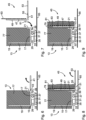
- the figures show various embodiments of plaster sealing strips 11 according to the invention for connecting a building element to a building wall, each in cross section.
- the plaster sealing strips 11 extend along a first or second longitudinal direction L 1 , L 2 running perpendicular to the plane of the image and have the cross section shown at least essentially over their entire longitudinal extent. Elements of different embodiments that correspond to one another are identified by the same reference numeral.
- Fig. 1 shows a base profile 13 of this plaster sealing strip 11, which comprises a profile body 15 extending along the first longitudinal direction L 1 , which in turn has a base leg 17, a plaster leg 19 and a limiting section 21.
- the base leg 17 extends with an at least substantially straight course along a base direction B, which is oriented perpendicular to the first longitudinal direction L 1.
- a spacer section 23 of the base leg 17 extends from an end 25 near the building to an end 27 far from the building, wherein the spacer section 23 corresponds to the entire base leg 17 in the first embodiment.
- the plaster leg 19 protrudes from the base leg 17 in a normal direction N oriented perpendicular to the base direction B and to the first longitudinal extension L 1 , while the boundary section 21 at the end 27 remote from the building also protrudes from the base leg 17 in the normal direction N.
- the length of the plaster leg 19 (along the normal direction N) is greater than the length of the base leg 23 (along the base direction B), while the length of the boundary section 21 (along the normal direction N) is less than the length of the base leg 23 (along the base direction B).
- the base profile 13 is a flat, at least substantially strip-shaped intermediate profile 31, which is aligned parallel to the base direction B.
- a first side surface of the intermediate profile 31 is connected to the fastening surface 29 via a first adhesive tape 33; a second adhesive tape 35 is adhered to a second side surface of the intermediate profile 31 opposite the first side surface, via which the intermediate profile 31 can be adhered to the respective component.
- the first adhesive tape 33 and the second adhesive tape 35 are each foam adhesive tapes. While the second adhesive tape 35 extends essentially over the entire extent of the intermediate profile 31 along the base direction B, the extent of the first adhesive tape 33 along the base direction B is shorter; in particular, it is less than half the extent of the intermediate profile 31 along the base direction B. As a result, there is a free space between the fastening surface 29 and the intermediate profile 31, which, with respect to the base direction B, lies between the first adhesive tape 33 and the end 27 of the spacer section 23 of the base leg 17 remote from the building.
- a membrane 37 Spanning this free space is a membrane 37, which is connected on the one hand to the fastening surface 29 and on the other hand to the intermediate profile 31, and whose cross-sectional length is greater than the thickness (extension along the normal direction N) of the first adhesive tape 33.
- the first adhesive tape 33 Due to the smaller extension along the base direction B and/or due to the formation of the respective adhesive connection, the first adhesive tape 33 has a lower adhesive force than the second adhesive tape 35. If the profile body 15 of the base profile 13 should move away from the respective component, for example for thermal reasons, the connection between the fastening surface 29 and the intermediate profile 31 is released, while the connection between the intermediate profile 31 and the component remains intact. However, the fastening surface 29 and the intermediate profile 31 then advantageously remain are still connected to each other via the membrane 37, so that the joint between the base profile 13 and the structural element remains sealed. In this way, the plaster sealing strip 11 allows for movement compensation while still providing reliable sealing.
- a coupling receptacle 39 of the base profile 13 is formed at the end 27 of the spacer section 23 of the base leg 17 remote from the building.
- This coupling receptacle 39 is essentially designed as a groove that extends along the first longitudinal direction L 1 and, in the first embodiment, has a C-shaped cross-section.
- the coupling receptacle 39 is formed on the side of the fastening surface 29 and is open in the base direction B (pointing away from the end 25 near the building).
- the base profile 13 further comprises a tear-off tab 41, which is connected to the end 27 of the spacer section 23 of the base leg 17 remote from the building via a predetermined breaking point 43 and is aligned parallel to the base direction B, so that it is arranged in direct extension of the base leg 17. Along the predetermined breaking point 43, the tear-off tab 41 can be separated from the profile body 15 of the base profile 13.
- the coupling receptacle 39 serves to couple the base profile 13 with a Fig. 2 separately shown additional profile 45.
- This additional profile 45 comprises a profile body 47 which extends in the second longitudinal direction L 2 , which in the coupled state of the plaster sealing strip 11 (ie when the base profile 13 and the additional profile 45 are coupled together; see e.g. Fig. 4 ) coincides with the first longitudinal direction L 1 .
- the profile body 47 of the additional profile 45 comprises a plaster leg 49, which is basically similar to the plaster leg 19 of the basic profile 13 and extends with at least a substantially straight course along a second Longitudinal direction L 2 extends vertically. In the coupled state of the plaster sealing strip 11, this direction corresponds to the aforementioned normal direction N.
- the profile body 47 of the additional profile 45 comprises a cover leg 51, which in the first embodiment protrudes perpendicularly from one end of the plaster leg 49.
- the cover leg 51 protrudes from the plaster leg 49 in the base direction B.
- the length of the cover leg 51 is significantly shorter than that of the plaster leg 49 of the additional profile 45.
- the additional profile 45 also has a tear-off tab 53, which is connected via a predetermined breaking point 55 to the cover leg 51, namely to an end of the cover leg 51 spaced from the cleaning leg 49.
- the tear-off tab 53 is arranged in direct extension of the cover leg 51 and, in the coupled state, is therefore aligned parallel to the base direction B.
- the tear-off tab 53 can be separated from the profile body 47 of the additional profile 45 along the predetermined breaking point 55.
- the covering leg 51 protrudes from a front side 57 of the plaster leg 49 of the additional profile 45.
- a coupling extension 61 is formed, which is at least substantially perpendicular to the plaster leg 49.
- the coupling extension 61 is designed as a web protruding from the rear side 59, the free end of which has a circular, thickened cross-section. As a result, this free end of the coupling extension 61 is at least substantially complementary to the C-shape of the coupling receptacle 39.
- the diameter of the circular shape is slightly larger than the opening of the C-shape, so that the opening is temporarily widened when the coupling extension 61 is inserted into the coupling receptacle 39 and, after insertion, engages behind the circular shape. In this way, the coupling extension 61 snaps into the coupling receptacle. 39 and is thus positively secured against leaving the coupling receptacle 39.
- the toothing is in each case so asymmetrical that when an attempt is made to pull the coupling extension 61 out of the coupling receptacle 39 in the opposite direction to the direction in which it was inserted into the coupling receptacle 39, the tooth flanks of the internal toothing of the coupling receptacle 39, which are oriented perpendicular to this direction, and the tooth flanks of the external toothing of the coupling extension 61, which are also oriented perpendicular to this direction, are pressed flat against each other and thereby block removal of the coupling extension 61 from the coupling receptacle 39.
- an irreversible coupling can be achieved by this type of design of the coupling receptacle 39 and the coupling extension 61, whereas the coupling of the first embodiment can also be released again.
- Fig. 4 are these in Fig. 1 shown basic profile 13 and the one in Fig. 2 shown additional profile 45 of the first embodiment of a plaster sealing strip 11 according to the invention in the coupled state. If the base profile 13 has the tear-off tab 41 as in the first embodiment, this must be used to couple the base profile 13 with the additional profile 45 by inserting the coupling extension 61 into the coupling receptacle 39 must first be separated from the profile body 15 at the predetermined breaking point 43. The tear-off tab 41 is then no longer part of the base profile 13 and therefore in Fig. 4 also not shown.
- the first longitudinal direction L 1 and the second longitudinal direction L 2 coincide; moreover, the cleaning leg 19 of the base profile 13 and the cleaning leg 49 of the additional profile 45 are then arranged at a distance from one another (with the length of the spacer section 23 at least substantially specifying the distance) and aligned parallel to one another.
- the cleaning leg 49 of the additional profile 45 then extends, like the cleaning leg 19 of the base profile 13, along the normal direction N, and the cover leg 51 of the additional profile 45 extends, like the base leg 17 of the base profile 13, along the base direction B.
- a reinforcing mesh 63 can be seen, which is arranged parallel to the plastering leg 49 of the additional profile 45 and projects beyond the plastering leg 49 parallel to the extension of the plastering leg 49 along the normal direction N.
- the reinforcing mesh 63 can generally only be arranged on the plastering leg 49 of the additional profile 45 after the coupling of the base profile 13 to the additional profile 45. Preferably, however, it is already firmly connected to the plastering leg 49 of the additional profile 45 from the outset and is thus part of the additional profile 45.
- the Fig. 5 shows a second embodiment of a plaster sealing strip 11 according to the invention, which differs from the first embodiment primarily in the structure of the base profile 13 and its attachment to the respective structural element 65; the additional profile 45 of the second embodiment, however, is at least substantially identical to the additional profile 45 of the first embodiment.
- the base leg 17 extends with a support section 67 beyond the building-proximate end 25 of the spacer section 23, at which the plaster leg 19 protrudes from the base leg 17.
- the support section 67 protrudes from the fastening surface 29 opposite the normal direction N and then merges into a contact section 69, which in turn is aligned parallel to the base direction B.
- An adhesive tape 71 is provided on the contact section 69, via which the base profile 13 can be adhered to the building element 65.
- a free space 73 inevitably remains between the fastening surface 29 and the structural element 65.
- a pre-compressed joint sealing tape 75 can be inserted into this free space 73, which can expand in the free space 73 and thus largely fill it. Should the adhesive tape 71 become detached from the base profile 13 or the structural element 65 due to a movement, in particular due to thermal factors, of the base profile 13 relative to the structural element 65, the joint sealing tape 75 can continue to fill the space between the fastening surface 29 and the structural element 65 by further expanding and thus reliably seal it.
- Fig. 6 to 9 Different states of the plaster sealing strip 11 are shown, which illustrate the process according to which a plaster sealing strip 11 according to the invention can be used for the structural connection of a building element to a building wall. This process is shown in the Fig. 6 to 9 shown as an example for the first embodiment; however, it also applies, where applicable, to other embodiments.
- the base profile 13 is attached to the building element 65 by being glued to the building element 65 (via the first adhesive tape 33 and the intermediate profile 31) with the second adhesive tape 35
- the base profile 13 was arranged such that its plaster leg 19 was arranged parallel to the building wall at a short distance (for example, a few centimeters) from the building wall (not shown), between which and the building element 65 the building structure connection is to be established.
- the plaster leg 19 was then plastered into a base plaster layer 77 on the building wall.
- a base plaster layer 77 was therefore applied to the building wall, surrounding the plaster leg 19 of the base profile 13, so that the plaster leg 19 is embedded (near the building wall) in the base plaster layer 77.
- the application of the base plaster layer 77 can be made easier in particular by the fact that the plaster leg 19 has a plurality of passages through which the plaster can penetrate.
- the base plaster layer 77 extends in a direction perpendicular to the building wall from the building wall to the boundary section 21 of the base profile 13, which serves as a marker and, if necessary, also as a removal aid for applying the base plaster layer 77 to the building wall.
- the tear-off tab 41 prevents plaster from getting onto the building element 65 or into the area between the base leg 17 of the base profile 13 and the building element 65 when the base plaster layer 77 is applied.
- a cover film can also be adhered to the tear-off tab 41.
- the coupling receptacle 39 formed on the base profile 13 is also protected from contamination by plaster by the tear-off tab 41.
- the tear-off tab 41 can be separated from the profile body 15 of the base profile 13 at the predetermined breaking point 43 (see arrow in Fig. 6 ).
- the coupling receptacle 39 is accessible, so that the coupling extension 61 of the additional profile 45 can be inserted into the coupling receptacle 39 and thus the additional profile 45 can be coupled to the base profile 13 (see arrow in Fig. 7 ).
- the plaster leg 49 of the additional profile 45 is in the then existing In the coupled state, the plaster sealing strip 11 is aligned parallel to the plaster leg 19 of the base profile 13 and arranged at a small distance (for example less than 1 cm) from the surface of the base plaster layer 77.
- a reinforcing mesh 63 is attached to the plaster leg 49 of the additional profile 45, which extends beyond the plaster leg 49 and thereby at least substantially along the surface of the base plaster layer 77. If the entire surface of the base plaster layer 77 is not covered by the reinforcing mesh 63 provided on the additional profile 45, a separate reinforcing mesh can additionally be arranged on the surface of the base plaster layer 77.
- the plaster leg 49 of the additional profile 45 is plastered into an additional plaster layer 79 on the base plaster layer 77.
- An additional plaster layer 79 has therefore been applied to the base plaster layer 77, surrounding the plaster leg 49 of the additional profile 45, so that the plaster leg 49, including the reinforcement mesh 63 provided on it and, if applicable, one or more further reinforcement meshes, is embedded in the additional plaster layer 79.
- a finishing plaster layer 81 has also been applied as part of the additional plaster layer 79 or on the additional plaster layer 79. Overall, the applied plaster extends in a direction perpendicular to the building wall up to the free end of the covering leg 51 of the additional profile 45.
- the tear-off tab 53 of the additional profile 45 also prevents plaster from reaching the structural element 65 or the area between the cover leg 51 of the additional profile 45 and the structural element 65 when applying the additional plaster layer 79 (including the top coat 81 if necessary).
- a cover film can also be glued onto the tear-off tab 53.
- the tear-off tab 53 can then be separated from the profile body 47 of the additional profile 45 along the predetermined breaking point 55 (see arrow in Fig. 8 ).
- the installation of the plaster sealing strip 11, including the plastering, is then complete. This state is shown in Fig. 9 shown.
- the two-part design of the plaster sealing strip 11 and the type of coupling of the base profile 13 and the additional profile 45 with parallel and spaced arrangement of their two plaster legs 19, 49 facilitate the application of a comparatively thick base plaster layer 77, in particular made of an (ultra-) lightweight plaster, as well as the application of an additional plaster layer 79 which stabilizes the base plaster layer 77 and is preferably provided with a reinforcing mesh 63 for this purpose.
- the plaster sealing strip 11 can simultaneously enable movement compensation and reliable sealing of the joint between the plaster layers 77, 79, 81 and the building wall 63.
Landscapes
- Engineering & Computer Science (AREA)
- Architecture (AREA)
- Civil Engineering (AREA)
- Structural Engineering (AREA)
- Finishing Walls (AREA)
Abstract
Description
- Die Erfindung betrifft eine Anputzdichtleiste für den Baukörperanschluss eines Bauelements, insbesondere eines Fensters, einer Tür, eines Rollladenkastens oder dergleichen, an einer Gebäudewand.
- Anputzdichtleisten dienen in der Regel zum Abdichten von Fugenbereichen, die zwischen einem Bauelement und Teilen eines Baukörpers, wie etwa einer Gebäudewand, gebildet sind, also zum Beispiel zwischen dem Blendrahmen eines Fensters oder einer Tür und dem sich daran anschließenden Mauerwerk. Auch an Übergängen von unterschiedlich gestalteten Wand- oder Fassadenabschnitten, wie zum Beispiel an der Übergangsstelle zwischen einer Holzvertäfelung und einer Putzfassade, werden Anputzdichtleisten der eingangs genannten Art verwendet. Demgemäß bilden auch Fassadenelemente, Wandverkleidungselemente, Paneele und dergleichen Bauelemente im Sinne der vorliegenden Offenbarung. Von der Dichtwirkung abgesehen sorgen Anputzdichtleisten für einen optisch ansprechenden Abschluss einer auf die Gebäudewand aufgetragenen Putzschicht.
- Zur Abdichtung einer Fuge zwischen dem Bauelement und der Gebäudewand kann die Anputzdichtleiste zumindest teilweise in diese Fuge eingesetzt werden. Für eine stabile Befestigung der Anputzdichtleiste und/oder zur Verstärkung einer Eckkante am Übergang von der Gebäudewand zur Fuge ist es zudem vorteilhaft, die Anputzdichtleiste zumindest teilweise an der Gebäudewand einzuputzen, also in eine an einer Wandfläche der Gebäudewand aufgetragene Putzschicht einzubetten. Dabei kann die Gebäudewand durch ein monolithisches Mauerwerk gebildet werden. Die Gebäudewand kann aber auch als Wärmedämmverbundsystem ausgebildet sein, so dass die Anputzdichtleiste an einer Wärmedämmung der Gebäudewand angebracht und eingeputzt wird. Zur Befestigung der Anputzdichtleiste ist es dabei zweckmäßig, an der Anputzdichtleiste Strukturen vorzusehen, die ein stabiles Einputzen ermöglichen.
- Insbesondere wenn es sich bei der Gebäudewand um ein monolithisches Mauerwerk handelt, kann es zweckmäßig sein, für das Einputzen oftmals (Ultra-)Leicht-putze zu verwenden, die vergleichsweise dick aufgetragen und zusätzlich mit einer vollflächigen Gewebespachtelung versehen werden, bevor anschließend der Auftrag eines Oberputzes erfolgen kann. Aber auch aus anderen Gründen kann es zweckmäßig sein, auf eine Gebäudewand zunächst eine vergleichsweise dicke Grundputzschicht aufzutragen, auf die anschließend eine oder mehrere weitere Putzschichten aufgetragen werden, die gemeinsam als Zusatzputzschicht betrachtet werden können, wobei in die Zusatzputzschicht, insbesondere in die unterste der genannten weiteren Putzschichten, vorteilhafterweise ein Armierungsgewebe eingebettet wird. Herkömmliche Anputzdichtleisten sind dabei nicht speziell für solche Dicklagenputzsysteme ausgelegt. Insbesondere bieten herkömmliche Anputzdichtleisten keine Unterstützung für das Auftragen einer oder mehrere weiterer Putzschichten auf eine vergleichsweise dicke Grundputzschicht.
- Es ist eine Aufgabe der Erfindung, eine Anputzdichtleiste für den Baukörperanschluss eines Bauelements an einer Gebäudewand bereitzustellen, die es vereinfacht, die Gebäudewand mit einer vergleichsweise dicken Grundputzschicht sowie einer auf die Grundputzschicht aufgetragenen Zusatzputzschicht zu versehen.
- Die Aufgabe wird gelöst durch eine Anputzdichtleiste mit den Merkmalen des Anspruchs 1. Vorteilhafte Ausführungsformen der Erfindung ergeben sich aus den Unteransprüchen, der vorliegenden Beschreibung sowie den Figuren.
- Die erfindungsgemäße Anputzdichtleiste für den Baukörperanschluss eines Bauelements, insbesondere eines Fensters oder einer Tür, an einer Gebäudewand umfasst ein Grundprofil und ein Zusatzprofil. Das Grundprofil und das Zusatzprofil sind dabei separat ausgebildet, d. h. als zwei grundsätzlich eigenständige Bauteile ausgebildet, insbesondere gesondert voneinander hergestellt. Die Anputzdichtleiste ist folglich mindestens zweiteilig ausgebildet. Insbesondere kann die Anputzdichtleiste aus dem Grundprofil und dem Zusatzprofil bestehen, also keine weiteren separaten Bauteile umfassen.
- Erfindungsgemäß weist das Grundprofil einen sich in eine erste Längsrichtung erstreckenden Profilkörper auf, der einen entlang einer Basisrichtung ausgerichteten Basisschenkel zur Befestigung an dem Bauelement und/oder an der Gebäudewand umfasst sowie einen Putzschenkel zum Einputzen in einer Grundputzschicht an der Gebäudewand umfasst, wobei der Putzschenkel in eine zumindest im Wesentlichen senkrecht zur Basisrichtung ausgerichtete Normalrichtung vom Basisschenkel vorsteht. Sowohl die Basisrichtung als auch die Normalrichtung sind dabei vorzugsweise orthogonal zu der genannten ersten Längsrichtung.
- Der Basisschenkel und der Putzschenkel können bezogen auf den Querschnitt des Profilkörpers des Grundprofils entlang ihres jeweiligen Verlaufs insbesondere eine zumindest im Wesentlichen konstante Dicke aufweisen. Diese Dicke kann beispielsweise mindestens 0,5 cm, insbesondere mindestens 0,8 cm, und/oder höchstens 1,5 cm, insbesondere höchstens 1,2 cm, betragen. Zudem können der Basisschenkel und der Putzschenkel jeweils durch einen oder mehrere flächig ausgebildete Abschnitte des Profilkörpers gebildet werden, die bezogen auf den Querschnitt des Profilkörpers jeweils einen geraden Verlauf aufweisen. Insbesondere der Putzschenkel kann insgesamt durch einen einzigen flächigen Abschnitt gebildet werden, so dass er im Querschnitt einen zumindest im Wesentlichen durchgehend geraden Verlauf aufweist. Da der Putzschenkel in die Normalrichtung vom Basisschenkel vorsteht, kann er sich insgesamt entlang dieser Normalrichtung erstrecken.
- Der Basisschenkel dient insofern der Befestigung an dem Bauelement und/oder der Gebäudewand, als das Grundprofil dazu ausgebildet ist, mit dem Basisschenkel an dem Bauelement und/oder der Gebäudewand befestigt zu werden. Vorzugsweise wird der Basisschenkel dabei zumindest mit dem Bauelement verbunden, wobei diese Verbindung insbesondere ein Aufkleben umfassen kann. Der Basisschenkel kann auch gleichzeitig sowohl mit dem Bauelement als auch mit der Gebäudewand verbunden sein. Insbesondere in diesem Fall kann die Verbindung - ausschließlich oder zusätzlich zu einer sonstiger Verbindungsart, wie etwa Kleben - kraftschlüssig sein, nämlich indem zumindest ein Teil des Basisschenkels zwischen dem Bauelement und der Gebäudewand eingeklemmt ist.
- Der Putzschenkel des Grundprofils ist insofern zum Einputzen an der Gebäudewand vorgesehen, als das Grundprofil dazu ausgebildet ist, dass es mit seinem Putzschenkel an der Gebäudewand (insbesondere mit zur Gebäudewand parallelem Putzschenkel) angeordnet wird und der Putzschenkel dann in der genannten Grundputzschicht an der Gebäudewand eingeputzt wird, so dass der Putzschenkel in der Grundputzschicht eingebettet ist. Insofern trägt auch der Putzschenkel zur Befestigung der Anputzdichtleiste an der Gebäudewand bei. In der Regel erfolgt das Einputzen des Putzschenkels jedoch später als die Befestigung des Basisschenkels an dem Bauelement und/oder der Gebäudewand. Für eine besonders stabile Einbettung des Putzschenkels in der Grundputzschicht weist der Putzschenkel vorzugsweise eine Vielzahl von Durchgängen auf, durch die der Putz den Putzschenkel beim Einputzen durchdringen kann. Zudem kann die Haftung des Putzes an dem Putzschenkel dadurch verbessert werden, dass der Putzschenkel zumindest einseitig, vorzugsweise beidseitig, eine die Putzverkrallung verbessernde Oberflächenprofilierung, zum Beispiel in Form von Rippen, Kerben und/oder Noppen, aufweist.
- Dass der Basisschenkel entlang der Basisrichtung ausgerichtet ist, kann insbesondere bedeuten, dass der Basisschenkel in die Basisrichtung seine größte Erstreckung quer zur ersten Längsrichtung aufweist und/oder dass er weitgehend oder überwiegend zumindest im Wesentlichen parallel zur Basisrichtung verläuft. Entlang der Basisrichtung kann sich der Basisschenkel beispielsweise über eine Länge von mindestens 10 cm, insbesondere mindestens 12 cm, vorzugweise mindestens 15 cm, erstrecken. Das Grundprofil kann insbesondere dazu ausgebildet sein, derart mit seinem Putzschenkel an der Gebäudewand eingeputzt zu werden, dass die Basisrichtung dabei zumindest im Wesentlichen senkrecht von der Gebäudewand weg weist.
- Der Putzschenkel ist relativ zum Verlauf des Basisschenkels gewinkelt ausgerichtet, da er in die genannte Normalrichtung vom Basisschenkel vorsteht, die zumindest im Wesentlichen senkrecht zur Einsetzrichtung ist. Entlang der Normalrichtung kann sich der Putzschenkel beispielsweise über eine Länge von mindestens 15 cm, insbesondere mindestens 20 cm, vorzugsweise mindestens 25 cm, erstrecken. Ferner ist es bevorzugt, dass der Putzschenkel eine größere Länge als der Basisschenkel aufweist.
- Der Profilkörper des Grundprofils ist vorzugsweise einteilig ausgebildet. Insbesondere sind also der Basisschenkel und der Putzschenkel dieses Profilkörpers nicht separat voneinander ausgebildet, sondern bilden lediglich aufgrund ihrer jeweiligen Struktur, insbesondere aufgrund ihres jeweiligen räumlichen Verlaufs, sowie ihrer jeweiligen Funktion unterschiedliche Abschnitte des Profilkörpers. Beispielweise kann der Profilkörper als Ganzes durch Extrusion hergestellt sein. Wenn der Profilkörper aus mehreren unterschiedlichen Materialien gebildet ist, kann er insbesondere durch Koextrusion hergestellt sein. Der Basisschenkel und der Putzschenkel des Profilkörpers weisen vorzugweise dasselbe Material auf und gehen unmittelbar ineinander über.
- Erfindungsgemäß weist das Zusatzprofil einen sich in eine zweite Längsrichtung erstreckenden Profilkörper auf, der einen Putzschenkel zum Einputzen in einer Zusatzputzschicht an der Grundputzschicht umfasst. Die Bezeichnung der genannten Längsrichtungen als erste Längsrichtung und zweite Längsrichtung dient dabei lediglich der begrifflichen Unterscheidung und soll weder eine Reihenfolge oder Hierarchie implizieren noch, dass die erste Längsrichtung und die zweite Längsrichtung zwangsläufig verschieden voneinander sein müssten. Sie müssen aber auch nicht ähnlich zueinander sein. Solange das Grundprofil und das Zusatzprofil nicht miteinander gekoppelt sind, ist die räumliche Ausrichtung der ersten Längsrichtung und der zweiten Längsrichtung relativ zueinander unbestimmt.
- Der Putzschenkel des Zusatzprofils kann dabei entlang einer zu der zweiten Längsrichtung orthogonalen Richtung ausgerichtet sein. Entlang dieser Richtung kann sich der Putzschenkel beispielsweise über eine Länge von mindestens 15 cm, insbesondere mindestens 20 cm, vorzugsweise mindestens 25 cm, erstrecken. Des Weiteren kann der Putzschenkel bezogen auf den Querschnitt des Profilkörpers des Zusatzprofils entlang seines jeweiligen Verlaufs insbesondere eine zumindest im Wesentlichen konstante Dicke aufweisen. Diese Dicke kann beispielsweise mindestens 0,5 cm, insbesondere mindestens 0,8 cm, und/oder höchstens 1,5 cm, insbesondere höchstens 1,2 cm, betragen. Ferner kann der Putzschenkel durch einen oder mehrere flächig ausgebildete Abschnitte des Profilkörpers gebildet werden, die bezogen auf den Querschnitt des Profilkörpers jeweils einen geraden Verlauf aufweisen. Insbesondere kann der Putzschenkel insgesamt durch einen einzigen flächigen Abschnitt gebildet werden, so dass er im Querschnitt einen zumindest im Wesentlichen durchgehend geraden Verlauf aufweist.
- Der Putzschenkel des Zusatzprofils ist insofern zum Einputzen an der Grundputzschicht vorgesehen, als das Zusatzprofil dazu ausgebildet ist, dass es mit seinem Putzschenkel an der Grundputzschicht, in der bereits der Putzschenkel des Grundprofils eingeputzt ist, (insbesondere parallel zu der Grundputzschicht) angeordnet wird und der Putzschenkel des Zusatzprofils dann in der genannten Zusatzputzschicht an der Grundputzschicht eingeputzt wird, so dass der Putzschenkel des Zusatzprofils in der Zusatzputzschicht eingebettet ist. Die Zusatzputzschicht kann dabei als Oberputzschicht ausgebildet sein, auf die keine weitere Putzschichten aufgetragen wird. Es kann aber auch vorgesehen sein, dass auf die Zusatzputzschicht noch zusätzlich ein Oberputz aufgetragen wird. Für eine besonders stabile Einbettung des Putzschenkels in der Zusatzputzschicht weist der Putzschenkel des Zusatzprofils vorzugsweise eine Vielzahl von Durchgängen auf, durch die der Putz den Putzschenkel beim Einputzen durchdringen kann. Zudem kann die Haftung des Putzes an dem Putzschenkel dadurch verbessert werden, dass der Putzschenkel zumindest einseitig, vorzugweise beidseitig, eine die Putzverkrallung verbessernde Oberflächenprofilierung, zum Beispiel in Form von Rippen, Kerben und/oder Noppen, aufweist.
- Der Putzschenkel des Zusatzprofils kann im Wesentlichen gleichartig zum Putzschenkel des Grundprofils ausgebildet sein. Insbesondere können der Putzschenkel des Grundprofils und der Putzschenkel des Zusatzprofils, etwa hinsichtlich ihrer äußeren Form, ihrer Maße, ihres Materials, ihrer Oberflächenstruktur und/oder der Anordnung von Durchgängen durch den jeweiligen Putzschenkel, identisch ausgebildet sein.
- Wie der Profilkörper des Grundprofils ist auch der Profilkörper des Zusatzprofils vorzugsweise einteilig ausgebildet, so dass insbesondere der Putzschenkel nicht separat von dem übrigen Profilkörper ausgebildet ist, sondern lediglich aufgrund seiner Struktur, insbesondere aufgrund seines räumlichen Verlaufs, sowie seiner Funktion einen von anderen Abschnitten des Profilkörpers verschiedenen Abschnitt des Profilkörpers bildet. Der Profilkörper des Zusatzprofils kann beispielsweise als Ganzes durch Extrusion oder, wenn er aus mehreren unterschiedlichen Materialien gebildet ist, durch Koextrusion hergestellt sein. Der Putzschenkel weist vorzugsweise dasselbe Material wie der übrige Profilkörper auf und geht unmittelbar in den übrigen Profilkörper, insbesondere in den weiter unten beschriebenen Abdeckschenkel des Profilkörpers des Zusatzprofils, über.
- Quer zu der ersten bzw. zweiten Längsrichtung können der Profilkörper des Grundprofils und der Profilkörper des Zusatzprofils jeweils einen zumindest im Wesentlichen konstanten Querschnitt aufweisen. Abweichungen von dem konstanten Querschnitt können sich insbesondere darauf beschränken, dass zumindest Teile des jeweiligen Profilkörpers Durchgänge und/oder eine Oberflächenprofilierung zur Verbesserung der Putzverkrallung aufweisen. Entlang der Längsrichtung kann sich der jeweilige Profilkörper über einige Meter erstrecken. Beispielweise können der Profilkörper des Grundprofils und der Profilkörper des Zusatzprofils jeweils eine Länge von etwa 2,5 m oder etwa 3 m aufweisen. Als Material können die Profilkörper jeweils einen Kunststoff oder ein Metall, beispielsweise ein Blech, aufweisen; vorzugsweise sind die Profilkörper aus Kunststoff, wie etwa einem PVC, insbesondere einem Hart-PVC, gebildet.
- Des Weiteren ist erfindungsgemäß vorgesehen, dass das Grundprofil (insbesondere der Basisschenkel des Grundprofils) einen Kopplungsfortsatz und das Zusatzprofil (insbesondere der Putzschenkel des Zusatzprofils) eine Kopplungsaufnahme aufweist oder, gerade umgekehrt, dass das Grundprofil (insbesondere der Basisschenkel des Grundprofils) eine Kopplungsaufnahme und das Zusatzprofil (insbesondere der Putzschenkel des Zusatzprofils) einen Kopplungsfortsatz aufweist. Diese beiden Alternativen schließen dabei einander nicht aus. Es kann also auch vorgesehen sein, dass das Grundprofil sowohl einen Kopplungsfortsatz als auch eine Kopplungsaufnahme aufweist und/oder das Zusatzprofil sowohl einen Kopplungsfortsatz als auch eine Kopplungsaufnahme aufweist. Zudem sind alle diese Fälle jeweils nicht auf nur genau einen Kopplungsfortsatz bzw. nur genau eine Kopplungsaufnahme beschränkt. Vielmehr können das Grundprofil und das Zusatzprofil jeweils auch mehrere Kopplungsfortsätze und/oder mehrere Kopplungsaufnahmen aufweisen.
- Vorzugsweise sind die Anzahl der Kopplungsfortsätze und die Anzahl der Kopplungsaufnahmen dabei gleich, so dass sich eine entsprechende Anzahl von Paarungen aus jeweils einem Kopplungsfortsatz und einer Kopplungsaufnahme bilden lässt (darunter die Paarung aus dem genannten einen Kopplungsfortsatz und der genannten einen Kopplungsaufnahme), wobei der Kopplungsfortsatz und die Kopplungsaufnahme einer jeweiligen Paarung an unterschiedlichen Profilen vorgesehen sind. Mit anderen Worten: Für jede Paarung ist dann entweder der Kopplungsfortsatz am Grundprofil und die Kopplungsaufnahme am Zusatzprofil vorgesehen oder aber der Kopplungsfortsatz am Zusatzprofil und die Kopplungsaufnahme am Grundprofil vorgesehen. Wenn das Grundprofil und das Zusatzprofil insgesamt mehrere Kopplungsfortsätze und Kopplungsaufnahmen aufweisen, gelten die im Folgenden für einen Kopplungsfortsatz und eine Kopplungsaufnahme beschriebenen Merkmale vorzugsweise auch für die weiteren Kopplungsfortsätze und weiteren Kopplungsaufnahmen, insbesondere für den Kopplungsfortsatz und die Kopplungsaufnahme jeder weiteren Paarung aus jeweils einem Kopplungsfortsatz und einer Kopplungsaufnahme.
- Vorzugsweise ist von den beiden Kopplungselementen (d. h. dem Kopplungsfortsatz und der Kopplungsaufnahme) das eine an dem Basisschenkel des Grundprofils und das andere an dem Putzschenkel des Zusatzprofils ausgebildet.
- Erfindungsgemäß sind das Grundprofil und das Zusatzprofil dazu ausgebildet, durch Einsetzen des Kopplungsfortsatzes in die Kopplungsaufnahme derart miteinander gekoppelt zu werden, dass der Putzschenkel des Grundprofils und der Putzschenkel des Zusatzprofils beabstandet voneinander angeordnet sowie zumindest im Wesentlichen parallel zueinander ausgerichtet sind.
- Durch das Koppeln des (an dem einen der beiden Profile ausgebildeten) Kopplungsfortsatz und der (an dem anderen der beiden Profile ausgebildeten) Kopplungsaufnahme (sowie gegebenenfalls eines oder mehrerer weiterer Kopplungsfortsätze mit einer jeweiligen weiteren Kopplungsaufnahme) wird die Anputzdichtleiste also in einen gekoppelten Zustand gebracht, in dem dann die Putzschenkel der beiden Profile beabstandet voneinander angeordnet sind sowie zumindest im Wesentlichen parallel zueinander ausgerichtet sind. Vorzugsweise werden das Grundprofil und das Zusatzprofil gerade und insbesondere ausschließlich durch die genannte Kopplung in einer definierten Ausrichtung zueinander gehalten (von möglichem Spiel abgesehen), in der die Putzschenkel zumindest im Wesentlichen parallel zueinander ausgerichtet sind. Vorzugsweise beträgt die Abweichung von einer exakt parallelen Ausrichtung höchstens 15°, weiter bevorzugt höchstens 10°, insbesondere höchstens 5°.
- Beim Einsetzen in die Kopplungsaufnahme kann der Kopplungsfortsatz in die Kopplungsaufnahme einrasten, wie weiter unten noch ausführlicher erläutert wird. Dabei können der Kopplungsfortsatz und die Kopplungsaufnahme derart ausgebildet sein, dass der Kopplungsfortsatz, nachdem er in die Kopplungsaufnahme eingesetzt worden ist, nicht mehr (jedenfalls nicht ohne Beschädigung zumindest eines Teils der Anputzdichtleiste) aus der Kopplungsaufnahme entnommen werden kann, so dass die Kopplung des Grundprofils und des Zusatzprofils miteinander irreversibel ist. Alternativ dazu kann aber auch vorgesehen sein, dass der Kopplungsfortsatz nach dem Einsetzen in die Kopplungsaufnahme aus der Kopplungsaufnahme auch wieder entnommen werden kann, gegebenenfalls unter Aufbringung einer gewissen Kraft zum Überwinden einer Rastwirkung.
- Der Kopplungsfortsatz und die Kopplungsaufnahme erstrecken sich jeweils vorzugsweise entlang der ersten Längsrichtung bzw. der zweiten Längsrichtung (je nachdem, an welchem Profil sie jeweils vorgesehen sind), insbesondere über die gesamte Länge des jeweiligen Profils. Der Kopplungsfortsatz kann beispielsweise als ein länglicher Stegabschnitt ausgebildet sein, wobei der Stegabschnitt in die jeweilige Längsrichtung vorzugsweise durchgehend ausgebildet ist, grundsätzlich aber auch Unterbrechungen aufweisen kann. Die Kopplungsaufnahme kann beispielsweise als eine längliche Nut ausgebildet sein, in die der Stegabschnitt eingesetzt werden kann, um das Grundprofil und das Zusatzprofil miteinander zu koppeln. Auch die Nut ist in die jeweilige Längsrichtung vorzugsweise durchgehend ausgebildet, kann aber grundsätzlich auch Unterbrechungen aufweisen. Die Tiefe der Nut kann dabei zumindest im Wesentlichen der Höhe des Stegabschnitts entsprechen. Durch ein tiefes Eingreifen des Kopplungsfortsatzes in die Kopplungsaufnahme können das Grundprofil und das Zusatzprofil (und somit deren Putzschenkel) im gekoppelten Zustand besonders stabil in einer definierten Ausrichtung zueinander gehalten werden.
- Im gekoppelten Zustand sind die erste Längsrichtung, in die sich das Grundprofil erstreckt, und die zweite Längsrichtung, in die sich das Zusatzprofil erstreckt, vorzugsweise parallel zueinander, wobei sich diese Ausrichtung vorteilhafter Weise automatisch aus der Kopplung durch das Einsetzen des Kopplungsfortsatzes in die Kopplungsaufnahme ergibt. Es ist daher nicht erforderlich, das Zusatzprofil eigens präzise an der Gebäudewand auszurichten. Das Einsetzen des Kopplungsfortsatzes in die Kopplungsaufnahme erfolgt vorzugsweise in eine zu den Längsrichtungen senkrechte Richtung, die insbesondere parallel zu der genannten Basisrichtung bzw. senkrecht zu der genannten Normalrichtung ausgerichtet ist. Aufgrund der parallelen Ausrichtung der Putzschenkel im gekoppelten Zustand, können sich im gekoppelten Zustand sowohl der Putzschenkel des Grundprofils als auch der Putzschenkel des Zusatzprofils entlang der Normalrichtung erstrecken.
- Der Abstand zwischen dem Putzschenkel des Grundprofils und dem Putzschenkel des Zusatzprofils im gekoppelten Zustand beträgt vorzugsweise mindestens 5 cm, weiter bevorzugt mindestens 10 cm, insbesondere mindestens 15 cm. Dieser Abstand ermöglicht es, auf das an der Gebäudewand angeordnete Grundprofil eine Grundputzschicht entsprechender Dicke aufzutragen und erst anschließend das Zusatzprofil mit dem Grundprofil zu koppeln, wobei der Putzschenkel des Zusatzprofils dann infolge der Kopplung zumindest im Wesentlichen an der Grundputzschicht anliegen kann. Wäre das Zusatzprofil dagegen von vornherein mit dem Grundprofil verbunden, würde es das Auftragen der Grundputzschicht behindern (in besonderem Maße, wenn es mit einem Armierungsgewebe versehen ist). Aufgrund der genannten Kopplung braucht das Zusatzprofil anders als das Grundprofil nicht sorgfältig an der Gebäudewand ausgerichtet zu werden, da sich eine präzise Ausrichtung des Zusatzprofils direkt aus der Kopplung mit dem bereits ausgerichteten Grundprofil ergibt.
- Nachdem das Zusatzprofil durch die Kopplung stabil an der Grundputzschicht angeordnet ist, kann auf die Grundputzschicht eine Zusatzputzschicht aufgetragen werden, in die der Putzschenkel des Zusatzprofils eingebettet wird. So können sowohl das Einputzen der Gebäudewand mit der Grundputzschicht als auch das Einputzen mit der Zusatzputzschicht jeweils durch eines der beiden genannten Profile der Anputzdichtleiste unterstützt werden. Entsprechend dem Abstand der Putzschenkel im gekoppelten Zustand kann die Grundputzschicht dabei vergleichsweise dick sein.
- Gemäß einer vorteilhaften Ausführungsform umfasst der Basisschenkel des Grundprofils einen Distanzabschnitt, der sich entlang der Basisrichtung von einem gebäudenahen Ende zu einem (dem gebäudenahen Ende bezüglich der Basisrichtung entgegengesetzten) gebäudefernen Ende erstreckt, wobei der Putzschenkel des Grundprofils an dem gebäudenahen Ende vom Basisschenkel (in die Normalrichtung) vorsteht und der Kopplungsfortsatz oder die Kopplungsaufnahme des Grundprofils am gebäudefernen Ende angeordnet ist. Der Kopplungsfortsatz bzw. die Kopplungsaufnahme ist dabei vorzugsweise an einer Seite des Basisschenkels angeordnet, die in die zur Normalrichtung entgegengesetzte Richtung weist. Der Kopplungsfortsatz bzw. die Kopplungsaufnahme und der Putzschenkel des Grundprofils, der in die Normalrichtung vorsteht, sind dann also nicht nur an entgegengesetzten Enden des Distanzabschnitts des Basisschenkels, sondern auch auf entgegengesetzten Seiten des Basisschenkels angeordnet.
- Die Bezeichnungen der Enden des Distanzabschnitts als gebäudenah bzw. gebäudefern dienen primär der begrifflichen Unterscheidung der beiden Enden. Denn ob sie tatsächlich gebäudenah bzw. gebäudefern sind, hängt natürlich davon ab, ob die Anputzdichtleiste an der Gebäudewand angeordnet ist. Allerdings ist die Anputzdichtleiste dazu ausgebildet, derart, insbesondere mit senkrecht zur Gebäudewand ausgerichteter Basisrichtung, an der Gebäudewand angeordnet zu werden, dass das gebäudenahe Ende des Distanzabschnitts der Gebäudewand näher ist als das gebäudeferne Ende des Distanzabschnitts.
- Der Distanzabschnitt weist entlang der Basisrichtung vorzugsweise eine Länge von mindestens 5 cm, weiter bevorzugt von mindestens 10 cm, insbesondere von mindestens 12 cm, auf. Beispielweise kann die Länge etwa 15 cm betragen. Ferner kann der Distanzabschnitt insgesamt als flächiger Abschnitt ausgebildet sein und im Querschnitt einen zumindest im Wesentlichen durchgehend geraden Verlauf parallel zur Basisrichtung aufweisen. Der Distanzabschnitt kann insbesondere demjenigen Teil des Basisschenkels entsprechen, der den Putzschenkel des Grundprofils mit dem Kopplungsfortsatz bzw. der Kopplungsaufnahme des Grundprofils verbindet. Grundsätzlich kann der Distanzabschnitt dabei auch dem gesamten Basisschenkel entsprechen.
- Gemäß einer vorteilhaften Ausführungsform umfasst der Profilkörper des Grundprofils einen Begrenzungsabschnitt, der an dem gebäudefernen Ende des Distanzabschnitts in die Normalrichtung von dem Basisschenkel vorsteht. Der Begrenzungsabschnitt steht somit in dieselbe Richtung von dem Basisschenkel vor wie der Putzschenkel und weist dabei einen durch die Länge des Distanzabschnitts definierten Abstand vom Putzschenkel auf. Dadurch kann der Begrenzungsabschnitt die Ebene definieren, bis zu der sich die Grundputzschicht von der Gebäudewand aus erstrecken soll. Aus diesem Grund kann der Begrenzungsabschnitt als Markierung und auch als Abziehhilfe für das Auftragen der Grundputzschicht an der Gebäudewand in geeigneter Dicke dienen. Der Begrenzungsabschnitt ist dabei vorzugsweise (bezüglich seiner Erstreckung entlang der Normalrichtung) wesentlich kürzer als der Putzschenkel des Grundprofils. Beispielsweise kann die Länge des Begrenzungsabschnitts entlang der Normalrichtung höchstens einem Drittel, vorzugsweise höchstens einem Viertel, insbesondere höchstens einem Fünftel, der Länge des Putzschenkels entlang der Normalrichtung entsprechen. Beispielsweise kann der Begrenzungsabschnitt eine Länge von höchstens 8 cm, vorzugsweise höchstens 6 cm, insbesondere höchstens 5 cm aufweisen.
- Gemäß einer weiteren vorteilhaften Ausführungsform weist das Grundprofil eine Abreißlasche auf, die über eine Sollbruchstelle mit dem Basisschenkel verbunden ist, wobei der Kopplungsfortsatz oder die Kopplungsaufnahme des Grundprofils (je nachdem, was davon an dem Grundprofil vorgesehen ist) relativ zu der Sollbruchstelle in zur Normalrichtung entgegengesetzter Richtung, vorzugsweise auch in zur Basisrichtung entgegengesetzter Richtung, angeordnet ist.
- Die Abreißlasche erstreckt sich vorzugsweise entlang der Basisrichtung, insbesondere zumindest im Wesentlichen in direkter Verlängerung des Basisschenkels oder zumindest des genannten Distanzabschnitts des Basisschenkels. Die Sollbruchstelle, über die die Abreißlasche mit dem Basisschenkel verbunden ist, kann insbesondere an dem genannten gebäudefernen Ende des Distanzabschnitts angeordnet sein. Die Sollbruchstelle kann beispielsweise durch einen Abschnitt verminderter Dicke gebildet werden, der aufgrund des geringeren Materials eine reduzierte Stabilität im Vergleich zum Basisschenkel und zur Abreißlasche aufweist. Alternativ oder zusätzlich dazu kann die Sollbruchstelle ein anderes, insbesondere weicheres, Material (z. B. Weich-PVC) als die Abreißlasche und der Basisschenkel aufweisen. In diesem Fall kann das Grundprofil durch Koextrusion hergestellt sein.
- Durch die genannte Anordnung des Kopplungsfortsatzes bzw. der Kopplungsaufnahme relativ zu der Sollbruchstelle kann insbesondere erreicht werden, dass der Kopplungsfortsatz bzw. die Kopplungsaufnahme bezüglich einer Blickrichtung entgegen der Normalrichtung, vorzugsweise auch bezüglich einer Blickrichtung mit Anteilen sowohl entgegen der Normalrichtung als auch entgegen der Basisrichtung, durch die Abreißlasche verdeckt angeordnet ist. Auf diese Weise schützt die Abreißlasche beim Auftragen der Grundputzschicht nicht nur das jeweilige Bauelement, sondern auch den Kopplungsfortsatz bzw. die Kopplungsaufnahme vor Verschmutzung durch den Putz. Allerdings kann aufgrund der genannten Anordnung der Abreißlasche das Koppeln des Zusatzprofils mit dem Grundprofil durch die Abreißlasche behindert werden. Insbesondere kann die Abreißlasche derart angeordnet sein, dass sie entlang der Sollbruchstelle von dem Grundprofil abgetrennt werden muss, bevor der Kopplungsfortsatz in die Kopplungsaufnahme eingesetzt werden kann, um auf diese Weise das Grundprofil und das Zusatzprofil miteinander zu koppeln.
- Gemäß einer weiteren vorteilhaften Ausführungsform weist der Putzschenkel des Zusatzprofils eine Rückseite, an der der Kopplungsfortsatz oder die Kopplungsaufnahme (je nachdem, was davon an dem Zusatzprofil vorgesehen ist) ausgebildet ist, und eine dazu (d. h. zur Rückseite) entgegengesetzte Vorderseite auf, wobei der Profilkörper des Zusatzprofils einen Abdeckschenkel umfasst, der an der Vorderseite des Putzschenkels des Zusatzprofils von diesem vorsteht.
- Der Abdeckschenkel steht vorzugsweise an einem von zwei Enden einer (im gekoppelten Zustand zur Normalrichtung parallelen) Längserstreckung des Putzschenkels des Zusatzprofils von dem Putzschenkel vor, insbesondere von demjenigen Ende, an dem auch der Kopplungsfortsatz bzw. die Kopplungsaufnahme näher angeordnet ist. Des Weiteren steht der Abdeckschenkel vorzugsweise zumindest im Wesentlichen senkrecht vom Putzschenkel vor. Das Zusatzprofil kann insofern zumindest im Wesentlichen (insbesondere lediglich vom Kopplungsfortsatz bzw. der Kopplungsaufnahme abgesehen) eine L-Form aufweisen. Grundsätzlich kann der Abdeckschenkel aber auch schräg ausgerichtet sein, wobei der Putzschenkel und der Abdeckschenkel dann vorzugsweise in einem stumpfen Winkel aufeinandertreffen. Die Länge des Abdeckschenkels entlang der Richtung, in die er von dem Putzschenkel vorsteht, kann beispielsweise höchstens einem Drittel, vorzugsweise höchstens einem Viertel, insbesondere höchstens einem Fünftel, der Länge des Putzschenkels des Zusatzprofils entsprechen. Beispielsweise kann der Abdeckschenkel eine Länge von höchstens 8 cm, vorzugsweise höchstens 6 cm, insbesondere höchstens 5 cm aufweisen.
- Der Abdeckschenkel des Zusatzprofils kann dazu dienen, die Zusatzputzschicht seitlich, insbesondere in Richtung zum Bauelement hin, zu begrenzen. Dabei ist die Anputzdichtleiste vorzugsweise dazu ausgebildet, dass, wenn das Grundprofil und das Zusatzprofil miteinander gekoppelt sind und die Anputzdichtleiste an der Gebäudewand und dem Bauelement montiert ist, zwischen dem Abdeckschenkel und dem Bauelement (zum Zwecke eines Bewegungsausgleich zwischen der Gebäudewand und dem Bauelement) eine Fuge verbleibt. Ein freies (von dem Putzschenkel wegweisendes) Ende des Abdeckschenkels kann zudem als Putzabzugskante für das Auftragen der Zusatzputzschicht und/oder für das Auftragen eines auf die Zusatzputzschicht aufgebrachten Oberputzes dienen.
- Gemäß einer weiteren vorteilhaften Ausführungsform weist das Zusatzprofil eine Abreißlasche auf, die über eine Sollbruchstelle mit dem Abdeckschenkel verbunden ist. Die Abreißlasche erstreckt sich vorzugsweise entlang derselben Richtung, entlang der auch der Abdeckschenkel ausgerichtet ist. Im gekoppelten Zustand kann diese Richtung insbesondere der Basisrichtung entsprechen. Die Abreißlasche kann sich ferner in direkter Verlängerung des Abdeckschenkels des Zusatzprofils erstrecken. Die Abreißlasche des Zusatzprofils kann insbesondere dazu dienen, das Bauelement beim Auftragen der Zusatzputzschicht vor Verschmutzung durch Putz zu schützen sowie zu vermeiden, dass Putz in die genannte Fuge zwischen dem Abdeckschenkel und dem Bauelement gelangt.
- Die Sollbruchstelle, über die die Abreißlasche mit dem Abdeckschenkel verbunden ist, kann insbesondere an dem genannten freien Ende des Abdeckschenkels angeordnet sein. Die Sollbruchstelle kann beispielsweise durch einen Abschnitt verminderter Dicke gebildet werden, der aufgrund des geringeren Materials eine reduzierte Stabilität im Vergleich zum Abdeckschenkel und zur Abreißlasche aufweist. Alternativ oder zusätzlich dazu kann die Sollbruchstelle ein anderes, insbesondere weicheres, Material (z. B. Weich-PVC) als die Abreißlasche und der Abdeckschenkel aufweisen. In diesem Fall kann das Zusatzprofil durch Koextrusion hergestellt sein.
- Gemäß einer weiteren vorteilhaften Ausführungsform ist an dem Putzschenkel des Zusatzprofils ein Armierungsgewebe befestigt, das sich über den Putzschenkel des Zusatzprofils hinaus erstreckt. Im gekoppelten Zustand erstreckt sich das Armierungsgewebe vorzugsweise in die Normalrichtung über den Putzschenkel des Zusatzprofils hinaus. Je nach Ausführungsform kann auch an dem Putzschenkel des Grundprofils einen Armierungsgewebe befestigt sein, das sich in die Normalrichtung über den Putzschenkel des Grundprofils hinaus erstreckt. Vorzugsweise weist jedoch nur der Putzschenkel des Zusatzprofils ein Armierungsgewebe auf.
- Das Armierungsgewebe unterstützt eine zuverlässige Einbettung des Zusatzprofils in die Zusatzputzschicht. Darüber hinaus kann es, insbesondere bei der Verwendung eines (Ultra-)Leichtputzes für die Grundputzschicht, zweckmäßig sein, die Grundputzschicht mit einer vollflächigen Gewebespachtelung zu versehen, indem in der Zusatzputzschicht über die gesamte verputzte Fläche eine Armierung in Form eines oder mehrerer Armierungsgewebe eingeputzt wird. Das an dem Putzschenkel des Zusatzprofils befestigte Armierungsgewebe kann zumindest einen Teil dieser Armierung bilden.
- Gemäß einer weiteren vorteilhaften Ausführungsform weist der Basisschenkel des Grundprofils eine Befestigungsfläche auf, die in zur Normalrichtung entgegengesetzte Richtung weist. Diese Fläche kann insbesondere eine Seitenfläche des genannten Distanzabschnitts des Basisschenkels sein. Vorzugsweise ist die Seitenfläche zumindest im Wesentlichen (insbesondere abgesehen von einer gegebenenfalls vorgesehenen Oberflächenstruktur) eben ausgebildet, liegt also in einer Ebene, wobei diese Ebene insbesondere parallel zur Basisrichtung sowie zur ersten Längsrichtung ausgerichtet sein kann. Die Befestigungsfläche kann einer Verbindung des Grundprofils mit dem Bauelement dienen, um das Grundprofil an dem Bauelement zu befestigen und/oder abzustützen und/oder einen Zwischenraum zwischen der Befestigungsfläche und dem Bauelement abzudichten.
- Gemäß einer vorteilhaften Ausführungsform sind an der Befestigungsfläche des Basisschenkels ein oder mehrere Befestigungsmittel zur Befestigung des Grundprofils an dem Bauelement und/oder ein oder mehrere Dichtmittel zum Abdichten eines Zwischenraums zwischen dem Grundprofil und dem Bauelement vorgesehen. Die genannte Befestigung kann sich auch auf eine Abstützung des Grundprofils an dem Bauelement beschränken.
- Die Befestigungsmittel können insbesondere als Mittel für eine Klebeverbindung ausgebildet sein und dazu beispielsweise ein oder mehrere, insbesondere doppelseitige, Klebebänder, vorzugsweise Schaumklebebänder, umfassen. Zum Beispiel können die Befestigungsmittel ein erstes Klebeband umfassen, das einerseits mit der Befestigungsfläche und andererseits mit einem, vorzugweise zumindest im Wesentlichen flächigen, insbesondere streifenförmigen, Zwischenprofil klebend verbunden ist, und ein zweites Klebeband umfassen, das einerseits mit dem Zwischenprofil klebend verbunden ist und andererseits zur klebenden Verbindung mit dem Bauteil ausgebildet ist. Bei dem ersten Klebeband und dem zweiten Klebeband handelt es sich dabei jeweils vorzugsweise um ein Schaumklebeband. Das Zwischenprofil kann einem Schenkel des Grundprofils oder des Zusatzprofils ähnlich ausgebildet sein, insbesondere eine ähnliche Dicke aufweisen und/oder aus einem ähnlichen Material, insbesondere einem Kunststoff, beispielsweise einem PVC, ausgebildet sein.
- Als Dichtmittel kann sich zwischen der Befestigungsfläche und dem genannten Zwischenprofil ferner eine abdichtende Membran erstrecken, die vorzugsweise relativ zum ersten Klebeband in die Basisrichtung (und somit von der Gebäudewand weiter entfernt als das erste Klebeband) angeordnet ist und deren Länge von der Befestigungsfläche zu dem Zwischenprofil größer als die Dicke des ersten Klebebands ist, wobei das erste Klebeband hinsichtlich der jeweiligen Haftkraft vorzugsweise dazu ausgebildet ist, sich eher von der Befestigungsfläche oder dem Zwischenprofil zu lösen als das zweite Klebeband von dem Zwischenprofil oder dem Bauelement. Auf diese Weise kann es bei einem beispielsweise thermisch bedingten Aufweiten der Fuge zwischen der Gebäudewand und dem Bauelement zwar dazu kommen, dass sich die Verbindung der Befestigungsfläche des Grundprofils mit dem Zwischenprofil über das dazwischen vorgesehene erste Klebeband löst, das Zwischenprofil dabei aber über das zweite Klebeband zuverlässig mit dem Bauelement und außerdem über die genannte Membran mit der Befestigungsfläche des Grundprofils verbunden bleibt. Auf diese Weise entsteht trotz des Aufweitens der Fuge und des Lösens des ersten Klebebands kein Durchgang zwischen der Befestigungsfläche und dem Zwischenprofil, sondern der genannte Zwischenraum zwischen dem Grundprofil und dem Bauelement bleibt insgesamt abgedichtet.
- Alternativ (grundsätzlich auch zusätzlich) zu einer Membran können die Dichtmittel auch ein vorkomprimiertes oder komprimierbares Fugendichtband (sogenanntes Kompriband) umfassen. Ein solches Fugendichtband ist typischerweise dazu ausgebildet, bei oder nach der Montage zu expandieren, um den Raum, in den es eingesetzt ist, (in diesem Fall den Zwischenraum zwischen der Befestigungsfläche des Basisschenkels des Grundprofils und dem Bauelement) abzudichten. Das Fugendichtband kann einseitig oder doppelseitig mit einer jeweiligen Klebeschicht versehen sein, um einerseits mit der Befestigungsfläche klebend verbunden oder jedenfalls verbindbar und gegebenenfalls andererseits mit dem Bauelement klebend verbindbar zu sein. Insbesondere kann vorgesehen sein, dass die Anputzdichtleiste bei der Montage über das Fugendichtband an dem Bauelement festgeklebt wird. Das Fugendichtband kann aber auch lediglich durch sein Expandieren kraftschlüssig zur Befestigung des Grundprofils an dem Bauelement beitragen. Insofern kann das Fugendichtband zugleich als Dichtmittel und als Befestigungsmittel dienen. Vorzugsweise umfassen die Befestigungsmittel jedoch auch dann, wenn die Dichtmittel ein Fugendichtband umfassen, noch zumindest ein Klebeband, insbesondere Schaumklebeband.
- Nicht alle Befestigungsmittel und/oder Dichtmittel brauchen jedoch von vornherein an der Anputzdichtleiste vorgesehen zu sein. Grundsätzlich können das eine oder die mehreren Befestigungsmittel oder zumindest einige der Befestigungsmittel und/oder das eine oder die mehreren Dichtmittel oder zumindest einige der Dichtmittel auch erst nachträglich vorgesehen werden. Das gilt insbesondere für ein Fugendichtband.
- Gemäß einer vorteilhaften Ausführungsform ist an der Befestigungsfläche des Basisschenkels ein Freiraum zur Aufnahme eines oder mehrerer Befestigungsmittel zur Befestigung des Grundprofils an dem Bauelement und/oder eines oder mehrerer Dichtmittel zum Abdichten eines Zwischenraums zwischen dem Grundprofil und dem Bauelement vorgesehen. Dieser Freiraum kann insbesondere dadurch gebildet werden, dass das Grundprofil zumindest einen Stützabschnitt aufweist, der entgegen der Normalrichtung von der Befestigungsfläche vorsteht, so dass die Befestigungsfläche nicht näher als ein bestimmter, durch die Länge des Stützabschnitts definierter Mindestabstand an das Bauelement angenähert werden kann und somit zwangsläufig der genannte Freiraum zwischen der Befestigungsfläche und dem Bauteil verbleibt. Dieser Freiraum wird dann seitlich, insbesondere entgegen der Basisrichtung, durch den Stützabschnitt begrenzt. In die Basisrichtung grenzt an den Freiraum vorzugsweise der Kopplungsfortsatz oder die Kopplungsaufnahme (je nachdem, was davon an dem Grundprofil vorgesehen ist) unmittelbar an.
- Der Freiraum kann insbesondere dazu dienen, ein Fugendichtband der genannten Art aufzunehmen. Das Fugendichtband kann, insbesondere nachdem das Grundprofil an der Gebäudewand angeordnet und gegebenenfalls über ein Befestigungsmittel an dem Bauelement befestigt worden ist, in komprimiertem Zustand in den Freiraum eingesetzt werden. Das Grundprofil ist dabei vorzugsweise bereits mit seinem Putzschenkel in der Grundputzschicht eingeputzt; das ist aber nicht zwingend erforderlich. Nach dem Einsetzen in den Freiraum kann das Fugendichtband expandieren, um den Zwischenraum zwischen der Befestigungsfläche und dem Bauelement abzudichten. Das Fugendichtband kann aber auch schon von vornherein, insbesondere schon bevor das Grundprofil an dem Bauelement angeordnet und gegebenenfalls befestigt worden ist, an der Befestigungsfläche angeordnet sein, dabei aber zunächst (etwa durch eine umhüllende Folie) in vorkomprimiertem Zustand gehalten werden und erst nach der Befestigung des Grundprofils an der Gebäudewand und/oder dem Bauelement für ein Expandieren freigegeben werden (etwa durch Durchtrennen oder Auflösen der Folie).
- Gemäß einer weiteren vorteilhaften Ausführungsform sind an der Kopplungsaufnahme und an dem Kopplungsfortsatz jeweils Rastmittel vorgesehen, wobei die Rastmittel der Kopplungsaufnahme (d. h. die an der Kopplungsaufnahme vorgesehenen Rastmittel) und die Rastmittel des Kopplungsfortsatzes (d. h. die an dem Kopplungsfortsatz vorgesehenen Rastmittel) beim Einsetzen des Kopplungsfortsatzes in die Kopplungsaufnahme einander bezüglich der Richtung des Einsetzens hintergreifen, so dass das Grundprofil und das Zusatzprofil durch das Hintergreifen formschlüssig gegen ein Lösen voneinander gesichert sind.
- Beispielweise kann der Kopplungsfortsatz an seiner Spitze im Querschnitt zumindest im Wesentlichen eine Kreisform aufweisen und die Kopplungsaufnahme im Querschnitt eine C-Form aufweisen, deren Innendurchmesser zumindest im Wesentlichen dem Außendurchmesser der genannten Kreisform entspricht. Beim Einsetzen des Kopplungsfortsatzes in die Kopplungsaufnahme müssen die Enden der C-Form daher vorübergehend aufgeweitet werden und hintergreifen anschließend (wenn die Kreisform vollständig in der C-Form aufgenommen ist) die C-Form bezüglich der Richtung des Einsetzens, so dass der Kopplungsfortsatz formschlüssig in der Kopplungsaufnahme gesichert ist.
- Des Weiteren können die Rastmittel beispielsweise einerseits (an dem Kopplungsfortsatz oder der Kopplungsaufnahme) zumindest einen Rastvorsprung und andererseits (an dem jeweiligen anderen dieser beiden Kopplungselemente) zumindest eine Rastausnehmung umfassen, wobei der Rastvorsprung derart elastisch ist, dass er beim Einsetzen des Kopplungsfortsatzes in die Kopplungsaufnahme ausgelenkt wird und spätestens nach dem vollständigen Einsetzen des Kopplungsfortsatzes in die Kopplungsaufnahme rückfedernden in die Rastausnehmung eingreift. Dieses Eingreifen erfolgt insbesondere in eine Richtung quer zur Richtung des Einsetzens und entspricht insofern bezüglich der Richtung des Einsetzens dem genannten Hintergreifen, welches den Kopplungsfortsatz dann formschlüssig dagegen sichert, die Kopplungsaufnahme entgegen der Richtung des Einsetzens zu verlassen.
- Der genannte Rastvorsprung kann insbesondere als Rastzunge oder nach Art eines Widerhakens oder einer Sperrklinke ausgebildet sein. Die Rastausnehmung kann im Wesentlichen komplementär zum Rastvorsprung ausgebildet sein. Zudem ist es denkbar, dass mehrere Rastausnehmungen vorgesehen sind, die nach Art einer Verzahnung angeordnet sind, wobei der Rastvorsprung beim Einsetzen des Kopplungsfortsatzes in die Kopplungsaufnahme nacheinander in eine jeweilige dieser Teilausnehmungen eingreift. Auf diese Weise kann nach Art eines Kabelbinders der Kopplungsfortsatz in mehreren unterschiedlichen Einsetztiefen in der Kopplungsaufnahme gesichert werden.
- Die Erfindung wird im Folgenden lediglich beispielhaft anhand der Figuren weiter erläutert.
- Fig. 1 und 2
- zeigen das Grundprofil bzw. das Zusatzprofil einer ersten Ausführungsform einer erfindungsgemäßen Anputzdichtleiste.
- Fig. 3
- zeigt zwei alternative Möglichkeiten der Ausbildung des Kopplungsfortsatzes und der Kopplungsaufnahme einer erfindungsgemäßen Anputzdichtleiste.
- Fig. 4
- zeigt die erste Ausführungsform einer erfindungsgemäßen Anputzdichtleiste in gekoppeltem Zustand.
- Fig. 5
- zeigt eine zweite Ausführungsform einer erfindungsgemäßen Anputzdichtleiste in gekoppeltem Zustand.
- Fig. 6 bis 9
- zeigen die erste Ausführungsform einer erfindungsgemäßen Anputzdichtleiste in vier unterschiedlichen Zuständen.
- In den Figuren sind verschiedene Ausführungsformen erfindungsgemäßer Anputzdichtleisten 11 für den Baukörperanschluss eines Bauelements an einer Gebäudewand jeweils im Querschnitt dargestellt. Die Anputzdichtleisten 11 erstrecken sich dabei jeweils entlang einer senkrecht zur Bildebene verlaufenden ersten bzw. zweiten Längsrichtung L1, L2 und weisen den gezeigten Querschnitt zumindest im Wesentlichen jeweils über ihre gesamte Längserstreckung auf. Elemente verschiedener Ausführungsformen, die einander entsprechen, sind dabei mit demselben Bezugszeichen gekennzeichnet.
- In den
Fig. 1, 2 und4 sowie 6 bis 9 sind jeweils zumindest Teile einer ersten Ausführungsform einer erfindungsgemäßen Anputzdichtleiste 11 dargestellt. DieFig. 1 zeigt ein Grundprofil 13 dieser Anputzdichtleiste 11, das einen sich entlang der ersten Längsrichtung L1 erstreckenden Profilkörper 15 umfasst, der seinerseits einen Basisschenkel 17, einen Putzschenkel 19 sowie einen Begrenzungsabschnitt 21 aufweist. Der Basisschenkel 17 erstreckt sich mit zumindest im Wesentlichen geradem Verlauf entlang einer Basisrichtung B, die senkrecht zur ersten Längsrichtung L1 ausgerichtet ist. Dabei erstreckt sich ein Distanzabschnitt 23 des Basisschenkels 17 von einem gebäudenahen Ende 25 zu einem gebäudefernen Ende 27, wobei der Distanzabschnitt 23 bei der ersten Ausführungsform dem gesamten Basisschenkel 17 entspricht. - An dem gebäudenahen Ende 25 steht der Putzschenkel 19 in eine zur Basisrichtung B sowie zur ersten Längserstreckung L1 senkrecht ausgerichtete Normalrichtung N vom Basisschenkel 17 vor, während der Begrenzungsabschnitt 21 an dem gebäudefernen Ende 27 ebenfalls in die Normalrichtung N von dem Basisschenkel 17 vorsteht. Die Länge des Putzschenkels 19 (entlang der Normalrichtung N) ist dabei größer als die Länge des Basisschenkels 23 (entlang der Basisrichtung B), während die Länge des Begrenzungsabschnitts 21 (entlang der Normalrichtung N) kleiner als die Länge des Basisschenkels 23 (entlang der Basisrichtung B) ist.
- Eine Seite des Basisschenkels 17 des Grundprofils 13, die in zur Normalrichtung N entgegengesetzte Richtung weist und somit zu dem Putzschenkel 19 und dem Begrenzungsabschnitt 21 entgegengesetzt ausgerichtet ist, bildet eine Befestigungsfläche 29 des Basisschenkels 17, über die das Grundprofil 13 an dem jeweiligen Bauelement (in
Fig. 1 nicht gezeigt) befestigt werden kann. Dazu umfasst das Grundprofil 13 bei der ersten Ausführungsform ein flächiges, zumindest im Wesentlichen streifenförmiges Zwischenprofil 31, das parallel zur Basisrichtung B ausgerichtet ist. Eine erste Seitenfläche des Zwischenprofils 31 ist über ein erstes Klebeband 33 mit der Befestigungsfläche 29 verbunden; an einer der ersten Seitenfläche entgegengesetzten zweiten Seitenfläche des Zwischenprofils 31 ist ein zweites Klebeband 35 festgeklebt, über das das Zwischenprofil 31 an das jeweilige Bauelement geklebt werden kann. - Bei dem ersten Klebeband 33 und dem zweiten Klebeband 35 handelt es sich jeweils um Schaumklebebänder. Während sich das zweite Klebeband 35 im Wesentlichen über die gesamte Erstreckung des Zwischenprofils 31 entlang der Basisrichtung B erstreckt, ist die Erstreckung des ersten Klebebands 33 entlang der Basisrichtung B kürzer; insbesondere beträgt sie weniger als die Hälfte der Erstreckung des Zwischenprofils 31 entlang der Basisrichtung B. Dadurch gibt es zwischen der Befestigungsfläche 29 und dem Zwischenprofil 31 einen Freiraum, der bezüglich der Basisrichtung B zwischen dem ersten Klebeband 33 und dem gebäudefernen Ende 27 des Distanzabschnitts 23 des Basisschenkels 17 liegt. Diesen Freiraum durchspannt eine Membran 37, die einerseits mit der Befestigungsfläche 29 und andererseits mit dem Zwischenprofil 31 verbunden ist und deren Länge im Querschnitt größer als die Dicke (Erstreckung entlang der Normalrichtung N) des ersten Klebebands 33 ist.
- Aufgrund der geringeren Erstreckung entlang der Basisrichtung B und/oder aufgrund der Ausbildung der jeweiligen Klebeverbindung weist das erste Klebeband 33 eine geringere Haftkraft auf als das zweite Klebeband 35. Falls sich der Profilkörper 15 des Grundprofils 13 beispielweise aus thermischen Gründen von dem jeweiligen Bauelement wegbewegen sollte, löst sich daher die Verbindung zwischen der Befestigungsfläche 29 und dem Zwischenprofil 31, während die Verbindung zwischen dem Zwischenprofil 31 und dem Bauelement bestehen bleibt. Allerdings bleiben die Befestigungsfläche 29 und das Zwischenprofil 31 dann vorteilhafterweise noch über die Membran 37 miteinander verbunden, so dass die Fuge zwischen dem Grundprofil 13 und dem Bauelement abgedichtet bleibt. Auf diese Weise ermöglicht die Anputzdichtleiste 11 einen Bewegungsausgleich und dennoch eine zuverlässige Abdichtung.
- An dem gebäudefernen Ende 27 des Distanzabschnitts 23 des Basisschenkels 17 ist eine Kopplungsaufnahme 39 des Grundprofils 13 ausgebildet. Diese Kopplungsaufnahme 39 ist im Wesentlichen als eine Nut ausgebildet, die sich entlang der ersten Längsrichtung L1 erstreckt und die bei der ersten Ausführungsform einen C-förmigen Querschnitt aufweist. Die Kopplungsaufnahme 39 ist auf der Seite der Befestigungsfläche 29 ausgebildet und in die Basisrichtung B (von dem gebäudenahen Ende 25 weg weisend) offen.
- Das Grundprofil 13 umfasst ferner eine Abreißlasche 41, die über eine Sollbruchstelle 43 mit dem gebäudefernen Ende 27 des Distanzabschnitts 23 des Basisschenkels 17 verbunden und parallel zur Basisrichtung B ausgerichtet ist, so dass sie in direkter Verlängerung des Basisschenkels 17 angeordnet ist. Entlang der Sollbruchstelle 43 kann die Abreißlasche 41 vom Profilkörper 15 des Grundprofils 13 abgetrennt werden.
- Die Kopplungsaufnahme 39 dient der Kopplung des Grundprofils 13 mit einem in
Fig. 2 separat gezeigten Zusatzprofil 45. Dieses Zusatzprofil 45 umfasst einen Profilkörper 47, der sich in die zweite Längsrichtung L2 erstreckt, die im gekoppelten Zustand der Anputzdichtleiste 11 (d. h. wenn das Grundprofil 13 und das Zusatzprofil 45 miteinander gekoppelt sind; vgl. z. B.Fig. 4 ) mit der ersten Längsrichtung L1 zusammenfällt. - Der Profilkörper 47 des Zusatzprofils 45 umfasst einen Putzschenkel 49, der dem Putzschenkel 19 des Grundprofils 13 grundsätzlich ähnlich ausgebildet ist und sich mit zumindest im Wesentlichen geradem Verlauf entlang einer zur zweiten Längsrichtung L2 senkrechten Richtung erstreckt. Im gekoppelten Zustand der Anputzdichtleiste 11 entspricht diese Richtung der genannten Normalrichtung N.
- Außerdem umfasst der Profilkörper 47 des Zusatzprofils 45 einen Abdeckschenkel 51, der bei der ersten Ausführungsform an einem Ende des Putzschenkels 49 senkrecht von diesem vorsteht. Im gekoppelten Zustand des Grundprofils 13 und des Zusatzprofils 45 steht der Abdeckschenkel 51 in die Basisrichtung B von dem Putzschenkel 49 vor. Die Länge des Abdeckschenkels 51 ist dabei wesentlich kürzer als die des Putzschenkels 49 des Zusatzprofils 45.
- Ähnlich wie das Grundprofil 13 weist auch das Zusatzprofil 45 eine Abreißlasche 53 auf, die über eine Sollbruchstelle 55 mit dem Abdeckschenkel 51, nämlich mit einem vom Putzschenkel 49 beabstandeten Ende des Abdeckschenkels 51 verbunden ist. Die Abreißlasche 53 ist dabei in direkter Verlängerung des Abdeckschenkels 51 angeordnet und im gekoppelten Zustand daher parallel zur Basisrichtung B ausgerichtet. Entlang der Sollbruchstelle 55 kann die Abreißlasche 53 vom Profilkörper 47 des Zusatzprofils 45 abgetrennt werden.
- Der Abdeckschenkel 51 steht von einer Vorderseite 57 des Putzschenkels 49 des Zusatzprofils 45 vor. An einer dazu entgegengesetzten Rückseite 59 des Putzschenkels 49 ist ein Kopplungsfortsatz 61 ausgebildet, der zumindest im Wesentlichen senkrecht zum Putzschenkel 49 ausgebildet ist. Der Kopplungsfortsatz 61 ist bei der ersten Ausführungsform als ein von der Rückseite 59 vorstehender Steg ausgebildet, dessen freies Ende im Querschnitt kreisförmig verdickt ist. Dadurch ist dieses freie Ende des Kopplungsfortsatzes 61 zumindest im Wesentlichen komplementär zur C-Form der Kopplungsaufnahme 39 ausgebildet. Allerdings ist der Durchmesser der Kreisform etwas größer als die Öffnung der C-Form, so dass die Öffnung bei einem Einsetzen des Kopplungsfortsatzes 61 in die Kopplungsaufnahme 39 vorübergehend geweitet wird und nach dem Einsetzen die Kreisform hintergreift. Auf diese Weise rastet der Kopplungsfortsatz 61 in die Kopplungsaufnahme 39 ein und ist dadurch formschlüssig gegen ein Verlassen der Kopplungsaufnahme 39 gesichert.
- Eine solche Rastwirkung ist jedoch nicht zwingend erforderlich, wie die obere der beiden in
Fig. 3 gezeigten alternativen Möglichkeiten der Ausbildung der Kopplungsaufnahme 39 und des Kopplungsfortsatzes 61 zeigt, bei der die Kopplungsaufnahme 39 zumindest im Wesentlichen eine U-Form mit geraden Schenkeln aufweist und der Kopplungsfortsatz als flacher Steg ohne verdicktes freies Ende ausgebildet ist. Die untere der beiden inFig. 3 gezeigten alternativen Ausbildungsmöglichkeiten ist der oberen sehr ähnlich und unterscheidet sich davon lediglich dadurch, dass die Kopplungsaufnahme 39 eine Innenverzahnung und der Kopplungsfortsatz 61 eine dazu komplementäre Außenverzahnung aufweist, die durch das Einsetzen des Kopplungsfortsatzes 61 in die Kopplungsaufnahme 39 ineinandergreifen. Die Verzahnung ist dabei jeweils derart asymmetrisch, dass beim Versuch, den Kopplungsfortsatz 61 entgegen der Richtung, in die er in die Kopplungsaufnahme 39 eingesetzt worden ist, aus der Kopplungsaufnahme 39 zu ziehen, senkrecht zu dieser Richtung ausgerichtete Zahnflanken der Innenverzahnung der Kopplungsaufnahme 39 und ebenfalls senkrecht zu dieser Richtung ausgerichtete Zahnflanken der Außenverzahnung des Kopplungsfortsatzes 61 flächig gegeneinandergedrückt werden und dadurch ein Entnehmen des Kopplungsfortsatzes 61 aus der Kopplungsaufnahme 39 sperren. Insofern kann durch diese Art der Ausbildung der Kopplungsaufnahme 39 und des Kopplungsfortsatzes 61 eine irreversible Kopplung erreicht werden, wohingegen die Kopplung der ersten Ausführungsform auch wieder gelöst werden kann. - In
Fig. 4 sind das inFig. 1 gezeigte Grundprofil 13 und das inFig. 2 gezeigte Zusatzprofils 45 der ersten Ausführungsform einer erfindungsgemäßen Anputzdichtleiste 11 in gekoppelten Zustand gezeigt. Wenn das Grundprofil 13 wie bei der ersten Ausführungsform die genannte Abreißlasche 41 aufweist, muss diese für das Koppeln des Grundprofils 13 mit dem Zusatzprofil 45 durch Einsetzen des Kopplungsfortsatzes 61 in die Kopplungsaufnahme 39 zunächst an der Sollbruchstelle 43 vom Profilkörper 15 abgetrennt werden. Die Abreißlasche 41 ist dann nicht mehr Teil des Grundprofils 13 und daher inFig. 4 auch nicht gezeigt. Im gekoppelten Zustand fallen die erste Längsrichtung L1 und die zweite Längsrichtung L2 zusammen; außerdem sind der Putzschenkel 19 des Grundprofils 13 und der Putzschenkel 49 des Zusatzprofils 45 dann beabstandet voneinander angeordnet (wobei die Länge des Distanzabschnitts 23 zumindest im Wesentlichen den Abstand vorgibt) sowie parallel zueinander ausgerichtet. Der Putzschenkel 49 des Zusatzprofils 45 erstreckt sich dann wie der Putzschenkel 19 des Grundprofils 13 entlang der Normalrichtung N, und der Abdeckschenkel 51 des Zusatzprofils 45 erstreckt sich wie der Basisschenkel 17 des Grundprofils 13 entlang der Basisrichtung B. - In
Fig. 4 ist ferner ein Armierungsgewebe 63 zu sehen, das parallel zum Putzschenkel 49 des Zusatzprofils 45 an dem Putzschenkel 49 angeordnet ist und parallel zur Erstreckung des Putzschenkels 49 entlang der Normalrichtung N über diesen übersteht. Das Armierungsgewebe 63 kann grundsätzlich erst nach der Kopplung des Grundprofils 13 mit dem Zusatzprofil 45 an dem Putzschenkel 49 des Zusatzprofils 45 angeordnet werden. Vorzugsweise ist es jedoch bereits von vornherein fest mit dem Putzschenkel 49 des Zusatzprofils 45 verbunden und somit Teil des Zusatzprofils 45. - Die
Fig. 5 zeigt eine zweite Ausführungsform einer erfindungsgemäßen Anputzdichtleiste 11, die sich von der ersten Ausführungsform vor allem durch die Struktur des Grundprofils 13 und dessen Befestigung an dem jeweiligen Bauelement 65 unterscheidet; das Zusatzprofil 45 der zweiten Ausführungsform ist dagegen zumindest im Wesentlichen identisch zu dem Zusatzprofil 45 der ersten Ausführungsform ausgebildet. - Bei der zweiten Ausführungsform erstreckt sich der Basisschenkel 17 mit einem Stützabschnitt 67 über das gebäudenahe Ende 25 des Distanzabschnitts 23, an dem der Putzschenkel 19 von dem Basisschenkel 17 vorsteht, hinaus. Der Stützabschnitt 67 steht entgegen der Normalrichtung N von der Befestigungsfläche 29 vor und geht dann in einen Anlageabschnitt 69 über, der wiederum parallel zur Basisrichtung B ausgerichtet ist. An dem Anlageabschnitt 69 ist ein Klebeband 71 vorgesehen, über welches das Grundprofil 13 an dem Bauelement 65 festgeklebt werden kann.
- Durch die gewinkelte Ausrichtung des Stützabschnitts 67 relativ zur Befestigungsfläche 29 verbleibt zwischen der Befestigungsfläche 29 und dem Bauelement 65 zwangsläufig ein Freiraum 73. In diesen Freiraum 73 kann ein vorkomprimiertes Fugendichtband 75 eingesetzt werden, das in dem Freiraum 73 expandieren und ihn somit weitgehend ausfüllen kann. Sollte sich aufgrund einer, insbesondere thermisch bedingten, Bewegung des Grundprofils 13 relativ zu dem Bauelement 65 das Klebeband 71 von dem Grundprofil 13 oder dem Bauelement 65 lösen, kann das Fugendichtband 75 durch weiteres Expandieren den Zwischenraum zwischen der Befestigungsfläche 29 und dem Bauelement 65 weiterhin ausfüllen und somit zuverlässig abdichten.
- In den
Fig. 6 bis 9 sind unterschiedliche Zustände der Anputzdichtleiste 11 gezeigt, anhand derer der Ablauf veranschaulicht wird, gemäß welchem eine erfindungsgemäße Anputzdichtleiste 11 für den Baukörperanschluss eines Bauelements an einer Gebäudewand eingesetzt werden kann. Dieser Ablauf ist in denFig. 6 bis 9 exemplarisch für die erste Ausführungsform gezeigt; er gilt jedoch, soweit anwendbar, in entsprechender Weise auch für andere Ausführungsformen. - In dem in
Fig. 6 gezeigten Zustand der Anputzdichtleiste 11 ist das Grundprofil 13 an dem Bauelement 65 befestigt, indem es (über das erste Klebeband 33 und das Zwischenprofil 31) mit dem zweiten Klebeband 35 an dem Bauelement 65 festgeklebt worden ist. Das Grundprofil 13 wurde dabei derart angeordnet, dass sein Putzschenkel 19 in geringem Abstand (beispielsweise von wenigen Zentimetern) zur Gebäudewand (nicht gezeigt), zwischen der und dem Bauelement 65 der Baukörperanschluss hergestellt werden soll, parallel zur Gebäudewand angeordnet ist. Der Putzschenkel 19 wurde anschließend in einer Grundputzschicht 77 an der Gebäudewand eingeputzt. Es wurde also eine Grundputzschicht 77 auf die Gebäudewand aufgetragen, die den Putzschenkel 19 des Grundprofils 13 umgibt, so dass der Putzschenkel 19 (gebäudewandnah) in die Grundputzschicht 77 eingebettet ist. Das Auftragen der Grundputzschicht 77 kann dabei insbesondere dadurch erleichtert sein, dass der Putzschenkel 19 eine Vielzahl von Durchgängen aufweist, durch die der Putz durch ihn hindurch dringen kann. - Die Grundputzschicht 77 erstreckt sich dabei in zur Gebäudewand senkrechter Richtung von der Gebäudewand bis zu dem Begrenzungsabschnitt 21 des Grundprofils 13, der als Markierung und gegebenenfalls auch als Abziehhilfe für das Auftragen der Grundputzschicht 77 an der Gebäudewand dient. Die Abreißlasche 41 verhindert dabei, dass beim Auftragen der Grundputzschicht 77 Putz an das Bauelement 65 oder in den Bereich zwischen dem Basisschenkel 17 des Grundprofils 13 und dem Bauelement 65 gelangt. Um das Bauelement 65 großflächig zu schützen, kann auf die Abreißlasche 41 zusätzlich eine Abdeckfolie aufgeklebt werden. Insbesondere wird auch die am Grundprofil 13 ausgebildete Kopplungsaufnahme 39 durch die Abreißlasche 41 vor Verschmutzung durch Putz geschützt.
- Wenn die Grundputzschicht 77 fertiggestellt ist, kann die Abreißlasche 41 an der Sollbruchstelle 43 vom Profilkörper 15 des Grundprofils 13 abgetrennt werden (vgl. Pfeil in
Fig. 6 ). Dadurch ist in dem inFig. 7 gezeigten Zustand der Anputzdichtleiste 11 die Kopplungsaufnahme 39 zugänglich, so dass der Kopplungsfortsatz 61 des Zusatzprofils 45 in die Kopplungsaufnahme 39 eingesetzt und somit insgesamt das Zusatzprofil 45 mit dem Grundprofil 13 gekoppelt werden kann (vgl. Pfeil inFig. 7 ). Der Putzschenkel 49 des Zusatzprofils 45 ist in dem dann vorliegenden gekoppelten Zustand der Anputzdichtleiste 11 parallel zum Putzschenkel 19 des Grundprofils 13 ausgerichtet und in geringem Abstand (beispielsweise von weniger als 1 cm) von der Oberfläche der Grundputzschicht 77 angeordnet. - Vorteilhafterweise ist an dem Putzschenkel 49 des Zusatzprofils 45 ein Armierungsgewebe 63 befestigt, das sich über den Putzschenkel 49 hinaus und dadurch zumindest im Wesentlichen entlang der Oberfläche der Grundputzschicht 77 erstreckt. Sofern nicht die gesamte Oberfläche der Grundputzschicht 77 von dem am Zusatzprofil 45 vorgesehenen Armierungsgewebe 63 abgedeckt wird, kann noch zusätzlich ein separates Armierungsgewebe an der Oberfläche der Grundputzschicht 77 angeordnet werden.
- In dem in
Fig. 8 gezeigten Zustand der Anputzdichtleiste 11 ist der Putzschenkel 49 des Zusatzprofils 45 in einer Zusatzputzschicht 79 an der Grundputzschicht 77 eingeputzt. Es wurde also auf die Grundputzschicht 77 noch eine Zusatzputzschicht 79 aufgetragen, die den Putzschenkel 49 des Zusatzprofils 45 umgibt, so dass der Putzschenkel 49 einschließlich den an ihm vorgesehenen Armierungsgewebes 63 sowie gegebenenfalls eines oder mehrerer weiterer Armierungsgewebe in die Zusatzputzschicht 79 eingebettet ist. Bei dem gezeigten Beispiel wurde zudem als Teil der Zusatzputzschicht 79 oder auf die Zusatzputzschicht 79 noch eine Oberputzschicht 81 aufgetragen. Insgesamt erstreckt sich der aufgetragene Putz in zur Gebäudewand senkrechte Richtung dann bis zum freien Ende des Abdeckschenkels 51 des Zusatzprofils 45. - Ähnlich wie beim Einputzen des Putzschenkels 19 des Grundprofils 13 wird durch die Abreißlasche 53 des Zusatzprofils 45 auch beim Einputzen des Putzschenkels 49 des Zusatzprofils 45 verhindert, dass beim Auftragen der Zusatzputzschicht 79 (gegebenenfalls einschließlich der Oberputzschicht 81) Putz an das Bauelement 65 oder in den Bereich zwischen dem Abdeckschenkel 51 des Zusatzprofils 45 und dem Bauelement 65 gelangt. Um das Bauelement 65 großflächig zu schützen, kann wiederum noch zusätzlich eine Abdeckfolie auf die Abreißlasche 53 aufgeklebt werden. Nachdem das Einputzen abgeschlossen ist kann die Abreißlasche 53 dann entlang der Sollbruchstelle 55 vom Profilkörper 47 des Zusatzprofils 45 abgetrennt werden (vgl. Pfeil in
Fig. 8 ). Die Montage der Anputzdichtleiste 11 einschließlich des Einputzens ist dann abgeschlossen. Dieser Zustand ist inFig. 9 gezeigt. - Die zweiteilige Ausbildung der Anputzdichtleiste 11 sowie die Art der Kopplung des Grundprofils 13 und des Zusatzprofils 45 mit paralleler und beabstandeter Anordnung ihrer beiden Putzschenkel 19, 49 erleichtern dabei das Auftragen einer vergleichsweise dicken Grundputzschicht 77, insbesondere aus einem (Ultra-) Leichtputz, sowie das Auftragen einer die Grundputzschicht 77 stabilisierenden und dazu vorzugsweise mit einem Armierungsgewebe 63 versehenen Zusatzputzschicht 79. Dabei kann die Anputzdichtleiste 11 zugleich einen Bewegungsausgleich sowie eine zuverlässige Abdichtung der Fuge zwischen den Putzschichten 77, 79, 81 und der Gebäudewand 63 ermöglichen.
-
- 11
- Anputzdichtleiste
- 13
- Grundprofil
- 15
- Profilkörper
- 17
- Basisschenkel
- 19
- Putzschenkel
- 21
- Begrenzungsabschnitt
- 23
- Distanzabschnitt
- 25
- gebäudenahes Ende
- 27
- gebäudefernes Ende
- 29
- Befestigungsfläche
- 31
- Zwischenprofil
- 33
- erstes Klebeband
- 35
- zweites Klebeband
- 37
- Membran
- 39
- Kopplungsaufnahme
- 41
- Abreißlasche
- 43
- Sollbruchstelle
- 45
- Zusatzprofil
- 47
- Profilkörper
- 49
- Putzschenkel
- 51
- Abdeckschenkel
- 53
- Abreißlasche
- 55
- Sollbruchstelle
- 57
- Vorderseite
- 59
- Rückseite
- 61
- Kopplungsfortsatz
- 63
- Armierungsgewebe
- 65
- Bauelement
- 67
- Stützabschnitt
- 69
- Anlageabschnitt
- 71
- Klebeband
- 73
- Freiraum
- 75
- Fugendichtband
- 77
- Grundputzschicht
- 79
- Zusatzputzschicht
- 81
- Oberputzschicht
- B
- Basisrichtung
- L1
- erste Längsrichtung
- L2
- zweite Längsrichtung
- N
- Normalrichtung
Claims (11)
- Anputzdichtleiste (11) für den Baukörperanschluss eines Bauelements (65), insbesondere eines Fensters oder einer Tür, an einer Gebäudewand, wobei die Anputzdichtleiste (11) ein Grundprofil (13) und ein Zusatzprofil (45) umfasst,wobei das Grundprofil (13) einen sich in eine erste Längsrichtung (L1) erstreckenden Profilkörper (15) aufweist, der einen entlang einer Basisrichtung (B) ausgerichteten Basisschenkel (17) zur Befestigung an dem Bauelement (65) und/oder an der Gebäudewand umfasst sowie einen Putzschenkel (19) zum Einputzen in einer Grundputzschicht (77) an der Gebäudewand umfasst, der in eine zumindest im Wesentlichen senkrecht zur Basisrichtung (B) ausgerichtete Normalrichtung (N) vom Basisschenkel (17) vorsteht,wobei das Zusatzprofil (45) einen sich in eine zweite Längsrichtung (L2) erstreckenden Profilkörper (47) aufweist, der einen Putzschenkel (49) zum Einputzen in einer Zusatzputzschicht (79) an der Grundputzschicht (77) umfasst,wobei das Grundprofil (13) einen Kopplungsfortsatz (61) und das Zusatzprofil (45) eine Kopplungsaufnahme (39) aufweist oder das Grundprofil (13) eine Kopplungsaufnahme (39) und das Zusatzprofil (45) einen Kopplungsfortsatz (61) aufweist,und wobei das Grundprofil (13) und das Zusatzprofil (45) dazu ausgebildet sind, durch Einsetzen des Kopplungsfortsatzes (61) in die Kopplungsaufnahme (39) derart miteinander gekoppelt zu werden, dass der Putzschenkel (19) des Grundprofils (13) und der Putzschenkel (49) des Zusatzprofils (45) beabstandet voneinander angeordnet sowie zumindest im Wesentlichen parallel zueinander ausgerichtet sind.
- Anputzdichtleiste nach Anspruch 1,
wobei der Basisschenkel (17) des Grundprofils (13) einen Distanzabschnitt (23) umfasst, der sich entlang der Basisrichtung (B) von einem gebäudenahen Ende (25) zu einem gebäudefernen Ende (27) erstreckt, wobei der Putzschenkel (19) des Grundprofils (13) an dem gebäudenahen Ende (25) vom Basisschenkel (17) vorsteht und der Kopplungsfortsatz (61) oder die Kopplungsaufnahme (39) des Grundprofils (13) am gebäudefernen Ende (27) angeordnet ist. - Anputzdichtleiste nach Anspruch 2,
wobei der Profilkörper (15) des Grundprofils (13) einen Begrenzungsabschnitt (21) umfasst, der an dem gebäudefernen Ende (27) des Distanzabschnitts (23) in die Normalrichtung (N) von dem Basisschenkel (17) vorsteht. - Anputzdichtleiste nach einem der vorstehenden Ansprüche,wobei das Grundprofil (13) eine Abreißlasche (41) aufweist, die über eine Sollbruchstelle (43) mit dem Basisschenkel (17) verbunden ist,und wobei der Kopplungsfortsatz (61) oder die Kopplungsaufnahme (39) des Grundprofils (13) relativ zu der Sollbruchstelle (43) in zur Normalrichtung (N) entgegengesetzter Richtung angeordnet ist.
- Anputzdichtleiste nach einem der vorstehenden Ansprüche,wobei der Putzschenkel (49) des Zusatzprofils (45) eine Rückseite (59) aufweist, an der der Kopplungsfortsatz (61) oder die Kopplungsaufnahme (39) ausgebildet ist, und eine dazu entgegengesetzte Vorderseite (57) aufweist, undwobei der Profilkörper (47) des Zusatzprofils (45) einen Abdeckschenkel (51) umfasst, der an der Vorderseite (57) des Putzschenkels (49) des Zusatzprofils (45) von diesem vorsteht.
- Anputzdichtleiste nach Anspruch 5,
wobei das Zusatzprofil (45) eine Abreißlasche (53) aufweist, die über eine Sollbruchstelle (55) mit dem Abdeckschenkel (51) verbunden ist. - Anputzdichtleiste nach einem der vorstehenden Ansprüche,
wobei an dem Putzschenkel (49) des Zusatzprofils (45) ein Armierungsgewebe (63) befestigt ist, das sich über den Putzschenkel (49) des Zusatzprofils (45) hinaus erstreckt. - Anputzdichtleiste nach einem der vorstehenden Ansprüche,
wobei der Basisschenkel (17) des Grundprofils (13) eine Befestigungsfläche (29) aufweist, die in zur Normalrichtung (N) entgegengesetzte Richtung weist. - Anputzdichtleiste nach Anspruch 8,
wobei an der Befestigungsfläche (29) des Basisschenkels (17) ein oder mehrere Befestigungsmittel (31, 33, 35, 75) zur Befestigung des Grundprofils (13) an dem Bauelement (65) und/oder ein oder mehrere Dichtmittel (37, 75) zum Abdichten eines Zwischenraums zwischen dem Grundprofil (13) und dem Bauelement (65) vorgesehen sind. - Anputzdichtleiste nach Anspruch 8 oder 9,
wobei an der Befestigungsfläche (29) des Basisschenkels (17) ein Freiraum (73) zur Aufnahme eines oder mehrerer Befestigungsmittel (31, 33, 35, 75) zur Befestigung des Grundprofils (13) an dem Bauelement (65) und/oder eines oder mehrerer Dichtmittel (37, 75) zum Abdichten eines Zwischenraums zwischen dem Grundprofil (13) und dem Bauelement (65) vorgesehen ist. - Anputzdichtleiste nach einem der vorstehenden Ansprüche,wobei an der Kopplungsaufnahme (39) und an dem Kopplungsfortsatz (61) jeweils Rastmittel vorgesehen sind, undwobei die Rastmittel der Kopplungsaufnahme (39) und die Rastmittel des Kopplungsfortsatzes (61) beim Einsetzen des Kopplungsfortsatzes (61) in die Kopplungsaufnahme (39) einander bezüglich der Richtung des Einsetzens hintergreifen, so dass das Grundprofil (13) und das Zusatzprofil (45) formschlüssig gegen ein Lösen voneinander gesichert sind.
Applications Claiming Priority (1)
| Application Number | Priority Date | Filing Date | Title |
|---|---|---|---|
| DE102023135176.1A DE102023135176A1 (de) | 2023-12-14 | 2023-12-14 | Anputzdichtleiste |
Publications (1)
| Publication Number | Publication Date |
|---|---|
| EP4571013A1 true EP4571013A1 (de) | 2025-06-18 |
Family
ID=93922879
Family Applications (1)
| Application Number | Title | Priority Date | Filing Date |
|---|---|---|---|
| EP24219368.8A Pending EP4571013A1 (de) | 2023-12-14 | 2024-12-12 | Anputzdichtleiste |
Country Status (2)
| Country | Link |
|---|---|
| EP (1) | EP4571013A1 (de) |
| DE (1) | DE102023135176A1 (de) |
Citations (1)
| Publication number | Priority date | Publication date | Assignee | Title |
|---|---|---|---|---|
| DE29822615U1 (de) * | 1998-11-11 | 2000-03-30 | Lorentz, Doris, 66333 Völklingen | System für Sockelleiste und Dehnfuge |
Family Cites Families (4)
| Publication number | Priority date | Publication date | Assignee | Title |
|---|---|---|---|---|
| DE29924216U1 (de) * | 1998-11-11 | 2002-08-14 | Lorentz, Doris, 66333 Völklingen | Randleiste für Wanddeckungen |
| AT8398U1 (de) * | 2005-06-23 | 2006-07-15 | Peter Kassmannhuber | Zweiteiliges laibungsanschlussprofil |
| DE102011004764A1 (de) * | 2011-02-25 | 2012-08-30 | August Braun | Anputzleiste sowie Bauwerksecke mit Anputzleiste |
| AT519110B1 (de) * | 2017-04-28 | 2018-04-15 | AF Tec Beteiligungs GmbH | Anschlussprofil für an putz angrenzende bauteile |
-
2023
- 2023-12-14 DE DE102023135176.1A patent/DE102023135176A1/de active Pending
-
2024
- 2024-12-12 EP EP24219368.8A patent/EP4571013A1/de active Pending
Patent Citations (1)
| Publication number | Priority date | Publication date | Assignee | Title |
|---|---|---|---|---|
| DE29822615U1 (de) * | 1998-11-11 | 2000-03-30 | Lorentz, Doris, 66333 Völklingen | System für Sockelleiste und Dehnfuge |
Also Published As
| Publication number | Publication date |
|---|---|
| DE102023135176A1 (de) | 2025-06-18 |
Similar Documents
| Publication | Publication Date | Title |
|---|---|---|
| DE20008712U1 (de) | Profilleiste zum Abdichten einer Bewegungsfuge zwischen einem Bauteil und einer Putzschicht | |
| DE102011102968B4 (de) | Haltevorrichtung und Verfahren zur Montage einer solchen | |
| DE20011013U1 (de) | Laibungsanschlußprofil | |
| EP2492429B3 (de) | Anputzleiste sowie Bauwerksecke mit Anputzleiste | |
| EP3009577B1 (de) | Dichtband | |
| DE202013101783U1 (de) | Wärmegedämmtes Aussteifungselement für einen Rollladenkasten und Rolladenkasten | |
| DE202013011085U1 (de) | Anputzleiste, Leiste und Abschlussschiene | |
| EP4571013A1 (de) | Anputzdichtleiste | |
| EP2708674B1 (de) | Anputzleiste und Putz-Eckleiste | |
| EP3992407B1 (de) | Dämmelement | |
| EP3848549B1 (de) | Anputzleiste sowie gebäude-übergang mit anputzleiste | |
| EP1956174B1 (de) | Profilschiene zum Positionieren eines Befestigungselements und Verfahren zum Herstellen einer Mehrfachverglasungseinheit | |
| AT8398U1 (de) | Zweiteiliges laibungsanschlussprofil | |
| DE29620179U1 (de) | Stoßprofil für Fenstereinbindungen | |
| EP2770134A1 (de) | Profilsystem für eine Gebäudefassade | |
| DE9315679U1 (de) | Fugenverschluß | |
| DE102004008831B4 (de) | Profil zum Abdecken von Dämmschichten | |
| DE2808328A1 (de) | Umsetzbares wandelement und in zweischalenbauweise daraus hergestelltes trennwandelement | |
| EP3587701B1 (de) | Anputzleisten-anordnung zum abdichten einer fuge | |
| EP4194638B1 (de) | Anputzdichtleiste | |
| EP1548197A1 (de) | Anordnung und Verfahren zum Abdichten von Fugen an Bauwerken, insbesondere von Dehnfugen in einer Aussenfassade | |
| DE202012007784U1 (de) | Zargenkonstruktion | |
| EP3832050B1 (de) | Abschlussprofil | |
| DE10145052B4 (de) | Satz von Innenfutterprofilleisten | |
| DE102018113031A1 (de) | Dachrandabschlussprofil sowie Verfahren zum Verlegen einer Dachabdeckbahn |
Legal Events
| Date | Code | Title | Description |
|---|---|---|---|
| PUAI | Public reference made under article 153(3) epc to a published international application that has entered the european phase |
Free format text: ORIGINAL CODE: 0009012 |
|
| STAA | Information on the status of an ep patent application or granted ep patent |
Free format text: STATUS: THE APPLICATION HAS BEEN PUBLISHED |
|
| AK | Designated contracting states |
Kind code of ref document: A1 Designated state(s): AL AT BE BG CH CY CZ DE DK EE ES FI FR GB GR HR HU IE IS IT LI LT LU LV MC ME MK MT NL NO PL PT RO RS SE SI SK SM TR |
|
| P01 | Opt-out of the competence of the unified patent court (upc) registered |
Free format text: CASE NUMBER: APP_30419/2025 Effective date: 20250625 |
|
| STAA | Information on the status of an ep patent application or granted ep patent |
Free format text: STATUS: REQUEST FOR EXAMINATION WAS MADE |
|
| 17P | Request for examination filed |
Effective date: 20251126 |
|
| GRAP | Despatch of communication of intention to grant a patent |
Free format text: ORIGINAL CODE: EPIDOSNIGR1 |
|
| STAA | Information on the status of an ep patent application or granted ep patent |
Free format text: STATUS: GRANT OF PATENT IS INTENDED |
|
| INTG | Intention to grant announced |
Effective date: 20260202 |
|
| RIC1 | Information provided on ipc code assigned before grant |
Ipc: E04F 13/06 20060101AFI20260123BHEP |