EP4571021A1 - Cylindre à levier, dispositif de fermeture, système et procédé - Google Patents
Cylindre à levier, dispositif de fermeture, système et procédé Download PDFInfo
- Publication number
- EP4571021A1 EP4571021A1 EP24218614.6A EP24218614A EP4571021A1 EP 4571021 A1 EP4571021 A1 EP 4571021A1 EP 24218614 A EP24218614 A EP 24218614A EP 4571021 A1 EP4571021 A1 EP 4571021A1
- Authority
- EP
- European Patent Office
- Prior art keywords
- cylinder
- core
- lever
- locking
- rotational position
- Prior art date
- Legal status (The legal status is an assumption and is not a legal conclusion. Google has not performed a legal analysis and makes no representation as to the accuracy of the status listed.)
- Pending
Links
Images


Classifications
-
- E—FIXED CONSTRUCTIONS
- E05—LOCKS; KEYS; WINDOW OR DOOR FITTINGS; SAFES
- E05C—BOLTS OR FASTENING DEVICES FOR WINGS, SPECIALLY FOR DOORS OR WINDOWS
- E05C3/00—Fastening devices with bolts moving pivotally or rotatively
- E05C3/02—Fastening devices with bolts moving pivotally or rotatively without latching action
- E05C3/04—Fastening devices with bolts moving pivotally or rotatively without latching action with operating handle or equivalent member rigid with the bolt
- E05C3/041—Fastening devices with bolts moving pivotally or rotatively without latching action with operating handle or equivalent member rigid with the bolt rotating about an axis perpendicular to the surface on which the fastener is mounted
- E05C3/042—Fastening devices with bolts moving pivotally or rotatively without latching action with operating handle or equivalent member rigid with the bolt rotating about an axis perpendicular to the surface on which the fastener is mounted the handle being at one side, the bolt at the other side or inside the wing
-
- E—FIXED CONSTRUCTIONS
- E05—LOCKS; KEYS; WINDOW OR DOOR FITTINGS; SAFES
- E05B—LOCKS; ACCESSORIES THEREFOR; HANDCUFFS
- E05B17/00—Accessories in connection with locks
- E05B17/22—Means for operating or controlling lock or fastening device accessories, i.e. other than the fastening members, e.g. switches, indicators
-
- E—FIXED CONSTRUCTIONS
- E05—LOCKS; KEYS; WINDOW OR DOOR FITTINGS; SAFES
- E05B—LOCKS; ACCESSORIES THEREFOR; HANDCUFFS
- E05B9/00—Lock casings or latch-mechanism casings ; Fastening locks or fasteners or parts thereof to the wing
- E05B9/04—Casings of cylinder locks
-
- E—FIXED CONSTRUCTIONS
- E05—LOCKS; KEYS; WINDOW OR DOOR FITTINGS; SAFES
- E05B—LOCKS; ACCESSORIES THEREFOR; HANDCUFFS
- E05B47/00—Operating or controlling locks or other fastening devices by electric or magnetic means
- E05B2047/0048—Circuits, feeding, monitoring
- E05B2047/0067—Monitoring
Definitions
- the present invention relates to a lever cylinder for locking a door or cover. Furthermore, the present invention relates to a locking device comprising such a lever cylinder and a key. Furthermore, the present invention relates to a system comprising such a locking device and an electrical circuit. Furthermore, the present invention relates to a method for locking and/or opening a door or cover using a lever cylinder.
- Lever cylinders and locking devices with lever cylinders are generally known in the state of the art.
- a lever cylinder can also be referred to as a lever lock or pivot lever lock.
- Lever cylinders or lever locks are used to lock doors or covers.
- a lever cylinder can be used to lock a mailbox, a locker, a workbench, a drawer, a cabinet, and especially a control cabinet. or a medicine cabinet, a slot machine, a cash box, or similar, can be locked.
- a cam cylinder typically consists of a locking cylinder and a lever.
- the lever can also be referred to as a tongue or pivot lever.
- the lever is located on the back of a cylinder housing of the locking cylinder and attached to a cylinder core of the locking cylinder, allowing the lever to rotate together with the cylinder core.
- the lever functions directly as a lock bolt, which can be moved or pivoted between an open and closed position by rotating the cylinder core, for example, via an inserted key.
- lever locks are also known in the prior art which, in addition to the purely mechanical locking, also actuate a switch, whereby the pivoting lever also actuates an electrical switch in an end position.
- lever cylinders are generally known in the state of the art.
- the printed matter DE 8807728 U1 a locking device for data processing equipment with a key-operated pivot lever lock which assumes a locking and an unlocking position using an over-dead-center spring and a microswitch which can be actuated with the aid of the pivot lever lock, wherein a curved, pre-tensioned leaf spring which operates over a dead center is rotatably fastened to the free end of a pivot lever which is rotatably mounted on a pivot axis and projects radially, wherein the leaf spring or the pivot lever is spatially assigned to a contact element of the microswitch in such a way that in the locking position either a partial area of the leaf spring or a partial area of the pivot lever presses against the contact element of the microswitch.
- EP 0 346 812 A2 that data processing equipment should be electrically and mechanically lockable, whereby regardless of a first mechanical locking, e.g. by covering the keyboard or the casing of a computer, a second mechanical locking device should be possible, for example by means of a cover for floppy disks and/or tape cassette drives. The second mechanical locking device should also still be possible after the locking device has been closed.
- a second actuating element designed as a bolt actuates a leaf spring with a locking lug in such a way that, among other things, the section of the leaf spring which, in the locking position, engages behind a support shoulder of a second part to be locked and which has the locking lug is lifted against a spring force independently of one another into the unlocking position either by the pivoting lever or by the second part to be locked.
- lever cylinders still leave room for improvement, particularly with regard to design, control and retrofitting.
- a lever cylinder for locking a door or cover wherein the lever cylinder has a locking cylinder and a lever, wherein the locking cylinder has a cylinder housing and a cylinder core, wherein the cylinder core is rotatable relative to the cylinder housing about a rotation axis between a first rotation position and a second rotation position, wherein the lever is connected to the cylinder core in a rotationally fixed manner about the rotation axis, wherein the locking cylinder further has a sensor device, wherein the sensor device is configured to detect a rotation of the cylinder core and/or a rotation position of the cylinder core.
- the lever cylinder is used to close or lock a door or cover.
- the door or cover can be opened and
- the lever cylinder can be mounted on the door or cover.
- the door or cover can have a recess or hole in which the lever cylinder can be mounted.
- the door or cover can be arranged at an access point to an environment.
- the access can be closed by means of the door or cover.
- the lever cylinder can serve to lock the door or cover against the environment.
- the environment can have a stop element.
- the lever cylinder can interact with the stop element to close the door or cover.
- the environment can, for example, be a housing.
- the housing can have a housing wall and optionally a groove.
- the housing or the housing wall can also have a groove or a striking plate.
- the housing wall, the groove, or the striking plate can serve as the stop element.
- the environment can, in particular, be a box, a cassette, a cabinet, a drawer, or a vending machine.
- the environment can be a mailbox, a locker, a workbench, a drawer, a switch cabinet, a medicine cabinet, another closed piece of furniture, a gaming machine, or a cash box.
- the lever of the lever cylinder is used to close or lock the door or cover.
- the lever can lock the door or cover against the environment.
- the lever can be movable between an open position and a closed position.
- the open position can also be referred to as the open position and the closed position as the closed position. In the closed position, the door or cover is locked.
- Turning or pivoting the lever into the open position can be referred to as the opening process.
- turning or pivoting the lever into the closed position can be referred to as the closing process.
- the lever can, for example, rest against the stop element in the closed position or be engaged with it.
- the door or cover is not locked and can therefore be opened.
- the lever can, for example, not rest against the stop element in the open position or be disengaged from it.
- the locking cylinder consists of a cylinder housing and a cylinder core.
- the cylinder housing can be mounted, for example, on the door or the cover.
- the cylinder core can rotate relative to the cylinder housing about the rotation axis.
- the cylinder core is mounted in the cylinder housing so that it can rotate about the rotation axis.
- the cylinder core has a substantially cylindrical shape. An axial direction, a radial direction, and a circumferential direction are defined according to this cylindrical shape.
- the rotation axis runs parallel to the axial direction. This means that the axial direction, the radial direction, and the circumferential direction are also defined by the rotation axis.
- the cylinder core can extend in the axial direction from a first core end to a second core end.
- the cylinder housing has a cylindrical bore.
- the cylinder core is arranged in the cylindrical bore and is mounted for rotation about the axis of rotation, i.e., in the circumferential direction.
- the diameter of the cylinder core can essentially correspond to the diameter of the cylindrical bore.
- the cylindrical bore can extend in the axial direction from a first housing end to a second housing end.
- the first core end can be arranged in the axial direction at the first housing end.
- the second core end can preferably be arranged outside the cylinder housing.
- the cylinder core can extend in the axial direction toward the second core end out of the cylinder housing, in particular beyond the second housing end.
- the lever can be arranged at the second core end or near the second core end. In particular, the lever can be arranged in the axial direction between the second housing end and the second core end.
- the lock cylinder may have a front side and a rear side in the axial direction.
- the first core end and the first housing end are arranged on the front side.
- the second core end and the second housing end are arranged on the rear side.
- the cylinder core is, in particular, rotatable about the rotational axis at least between the first rotational position and the second rotational position.
- the cylinder core is mounted in the cylinder housing so as to be rotatable about the rotational axis between the first rotational position and the second rotational position.
- the first rotational position and the second rotational position about the rotational axis can be offset from one another by an angle between 30° and 180°, preferably 60° to 135°, in particular 90°.
- the cylinder core can be axially secured in the cylinder housing by a stop pin that engages a core groove of the cylinder core, and its angle of rotation can be limited.
- the core groove can extend only so far in the direction of rotation that the stop pin limits the angle of rotation to a rotation range between the first rotational position and the second rotational position.
- the lever is connected to the cylinder core in a rotationally fixed manner about the rotation axis.
- the lever can be mounted on the cylinder core.
- the lever can then be rotated together with the cylinder core about the rotation axis.
- the lever In the second rotational position of the cylinder core, the lever can be arranged in the open position.
- the lever In the first rotational position of the cylinder core, the lever can be arranged in the closed position. In particular, if the cylinder core is not arranged in the second rotational position, the lever can be arranged in the closed position.
- the locking cylinder may further comprise one or more locking devices, wherein the one or more locking devices block a rotational movement of the cylinder core relative to the cylinder housing in a locked state and release a rotational movement of the cylinder core relative to the cylinder housing in a released state.
- the locking devices can be designed, for example, as pin tumblers or disc tumblers.
- the locking devices are used to query the security features of a key.
- a key can generally have one or more security features that can be interrogated using the locking devices.
- a security feature of the key can, for example, be a projection, a recess, a movable element, or a specific surface profile.
- Each locking device can be assigned to a corresponding security feature of the key. In other words, each locking device is used to interrogate the corresponding security feature.
- Each locking device can have a locked position and a released position. In the locked position, a locking device blocks the rotation of the cylinder core. In the released position, the locking device allows the rotation of the cylinder core.
- each locking device can be designed such that the locking device has the locked position as its default position, i.e., without positive query of the corresponding security feature. By positive query of the corresponding security feature, the locking device can be transferred from the locked position to the released position.
- the locking cylinder can thus be designed such that the locking cylinder has the locked state as its default state and can only be transferred to the released state upon positive query of all locking devices.
- the cylinder core may further comprise a keyway, wherein the locking cylinder can be transferred from the locked state to the released state by fully inserting a key into the keyway.
- the keyway preferably extends in the axial direction.
- the keyway can be open toward the first core end.
- the keyway can thus have an opening at the first core end.
- the key can be inserted or inserted into the keyway through this opening.
- the key is inserted into the keyway of the cylinder core in an insertion direction and removed from the keyway of the cylinder core in the opposite direction to the insertion direction.
- the insertion direction corresponds to the axial direction.
- the locking cylinder is designed so that when the key is fully inserted, all locking devices positively query the corresponding security features of the key, thereby transferring the locking cylinder to the release state. In particular, positively querying the security features transfers the corresponding locking devices to the release position. If the key is not inserted or not fully inserted into the keyway, the locking cylinder is in the locked state. In particular, at least not all of the key's security features are positively interrogated, so at least one locking device is in the locked position.
- the locking cylinder will also remain locked if an incorrect key is used.
- a wrong key is one that does not have the appropriate security features.
- the locking cylinder additionally comprises a sensor device.
- the sensor device can, in particular, be integrated into the locking cylinder.
- the sensor device is configured to detect a rotational position of the cylinder core or a rotation of the cylinder core.
- a rotation of the cylinder core corresponds to a change in the rotational position.
- the sensor device can detect whether the cylinder core is arranged in the first rotational position or the second rotational position.
- the sensor device can detect whether and/or how the cylinder core is rotated between the first rotational position and the second rotational position.
- the sensor device can thus detect the rotational position of the cylinder core or how the cylinder core is rotated, for example in Towards or into the second rotational position or towards or into the first rotational position. By detecting the cylinder rotation, it can also be determined whether the lever is in the open or closed position.
- the detected rotational position and/or the detected rotation of the cylinder core can then be used, for example, to control an electrical circuit.
- further electronics can be controlled via this.
- lighting or an actuator can be switched on based on the detected rotational position and/or the detected rotation.
- an additional security level such as a mechatronic locking box can be released based on the detected rotational position and/or the detected rotation.
- an opening process can be logged in a memory device based on the detected rotational position and/or the detected rotation.
- the lever cylinder according to the first aspect thus enables simple detection of the cylinder rotation within the locking cylinder using an integrated sensor device. This achieves a compact design. Furthermore, no additional detection devices outside the lever cylinder are required. Furthermore, such a lever cylinder can also be easily retrofitted to existing doors or covers.
- a locking device comprising the lever cylinder according to the first aspect and a key.
- the locking device thus comprises the lever cylinder and the key.
- the key is used to operate the lever cylinder.
- the key can be fully inserted into the keyway of the cylinder core, for example, which sets the locking cylinder to the release position. With the key fully inserted, the cylinder core can be rotated between the first and second positions by turning the key.
- the sensor device detects a rotation of the cylinder core, in particular into the second rotational position, it can be concluded that the lever cylinder has been actuated or opened using the key.
- a system comprising the locking device according to the second aspect and an electrical circuit, wherein the electrical circuit is controllable on the basis of the detected rotation or the detected rotational position of the cylinder core.
- the electrical circuit can be constructed from electrical or electromechanical elements combined into a functional arrangement. These elements can include, for example, batteries, switches, displays, motors, but also simple components such as resistors, capacitors, coils, or transistors. In particular, the electrical circuit can be an electronic circuit.
- the electrical circuit is controlled based on the detected rotation or the detected rotational position of the cylinder core.
- the electrical circuit can be switched via the sensor device.
- the sensor device can, for example, have a switching element that is switched upon a certain rotation of the cylinder core or upon reaching a certain rotational position of the cylinder core.
- the switching element can, for example, be a push-button, a normally open contact, or an normally closed contact.
- the switching element can be actuated by rotation of the cylinder core.
- an electrical circuit of the electrical circuit can be closed by means of the switching element when the switching element is actuated.
- the switching element can be actuated by rotating the cylinder core using the corresponding key in order to close or open the circuit depending on the direction of rotation.
- the sensor device can detect information regarding the rotation and/or the rotational position of the cylinder core, which information is evaluated in order to then carry out corresponding control of the electrical circuit. For example, it can be evaluated whether a certain rotation has occurred, in particular a rotation into the first or second rotational position or in the direction of the first or second rotational position. On the basis of this evaluation, corresponding control of the electrical circuit can then be carried out.
- the rotational position can also be evaluated to determine whether the rotational position has changed. Based on the change in the rotational position, it can be determined whether a rotation has occurred. On the basis of the determined rotation, corresponding control of the electrical circuit can then be carried out. Furthermore, it can also be determined whether the detected rotational position is a certain rotational position, in particular the first rotational position or the second rotational position. If the detected rotational position corresponds to the determined rotational position, corresponding control of the electrical circuit can be carried out.
- the system may further comprise the door or cover.
- the system may also comprise the surrounding area, in particular the housing, whose access can be closed with the door or cover.
- the electrical circuit may be arranged in the door and/or in the surrounding area, in particular in or on the housing.
- the controlling step can be performed, for example, by means of the sensor device. Alternatively, the controlling step can also be performed by means of a control device of the electrical circuit.
- a lever cylinder is thus provided that includes a core rotation detection function.
- This is a complete mechanical lever cylinder with integrated locking detection.
- Logic for controlling an electrical circuit can be arranged outside the locking cylinder, for example, in a control device.
- the lever cylinder, locking device, system, and method according to the aspects of the invention thus achieve a simple and compact design. Furthermore, the electrical circuit can be controlled easily and in a variety of ways. Furthermore, the lever cylinder can be easily retrofitted to existing doors and covers.
- the sensor device may comprise a mechanical sensor and/or a magnetic sensor and/or an inertial sensor and/or a position sensor.
- These sensors can detect the rotation of the cylinder core and/or its rotational position. In particular, several of these sensors can be used together. This can increase the accuracy of the detection.
- the mechanical sensor can mechanically detect the rotation or rotational position of the cylinder core.
- the mechanical sensor can, for example, be a mechanical switching element, in particular a pushbutton, a normally open contact, or an normally closed contact.
- the mechanical sensor can query a rotation or rotational position, in particular the reaching of a specific rotational position.
- the mechanical sensor can, for example, have a query element.
- the mechanical sensor can be designed as a pushbutton that is actuated in a specific rotational position by the cylinder core or by rotating the cylinder core into a specific rotational position.
- the magnetic sensor can magnetically detect the rotation or rotational position of the cylinder core.
- the sensor can, for example, detect the change in the magnetic field of a magnetic element relative to the magnetic sensor when the cylinder core rotates.
- the magnetic element can be arranged in the cylinder core and the magnetic sensor in or on the cylinder housing, or vice versa. The magnetic sensor can thus detect a movement of the magnetic element relative to the magnetic sensor when the cylinder core rotates and use this to detect the cylinder core rotation.
- the inertial sensor is preferably arranged in the cylinder core.
- An inertial sensor can be an acceleration sensor or a yaw rate sensor.
- An acceleration sensor is a sensor that measures its acceleration. The acceleration measurement can be carried out by determining the inertial force acting on a test mass.
- a yaw rate sensor is a sensor that measures the rotational speed of a body. Based on the measured acceleration or yaw rate, it can be determined whether the cylinder core is rotated or in which direction and/or where the cylinder core is rotated. In particular, based on the measured acceleration or The rotation rate determines whether the cylinder core is rotated towards or into the first or second rotation position.
- the position sensor is preferably arranged on or in the cylinder housing.
- the position sensor is a sensor that can detect the position of a body.
- Position sensors can be, for example, mechanical sensors, inductive sensors, capacitive sensors, magnetic sensors, or optical sensors that can detect switching flags or specific objects or patterns.
- the position sensor can, for example, be configured to detect a rotational position of the cylinder core, in particular the first or second rotational position.
- the sensor device can be configured to output a sensor signal to an electrical circuit, wherein the sensor signal contains information regarding the detected rotation of the cylinder core or the detected rotational position of the cylinder core.
- the electrical circuit can be controlled particularly flexibly and in a variety of ways.
- the sensor signal can, in particular, be output or sent to a control device of the electrical circuit.
- the sensor device can communicate with the control device via wired or wireless communication.
- the sensor device can output the sensor signal when rotation is detected or when the rotational position of the cylinder core has changed.
- the sensor device can also output the sensor signal continuously or periodically, for example, to output or send the current rotational position of the cylinder core.
- the sensor device can be configured to control an electrical circuit based on the detected rotation of the cylinder core and/or the detected rotational position of the cylinder core.
- the electrical circuit can be switched via the sensor device depending on the detected rotation and/or the detected rotational position.
- the sensor device can, for example, close a circuit of the electrical circuit when the cylinder core is turned to the second rotational position and open the circuit when the cylinder core is turned to the first rotational position.
- the electrical circuit has lighting that is arranged within the environment, in particular within the housing. The lighting is then switched on when the door or cover is opened and switched off when it is closed.
- the sensor device can close a circuit of the electrical circuit when the cylinder core is turned to the first rotational position and open the circuit when the cylinder core is turned to the first rotational position. This is advantageous, for example, if the electrical circuit has to be switched off when the door or cover is open for safety reasons.
- the sensor device can be arranged on and/or in the cylinder housing.
- the sensor device is particularly suitable when the sensor device is operated via a cable.
- the sensor device can also be located in the cylinder core. In this arrangement, a wireless sensor is advantageous.
- the cylinder housing may have a recess in which the sensor device is arranged.
- the recess can extend in the radial direction up to the cylindrical bore.
- the recess can be open towards the cylindrical bore.
- the recess can thus be open radially inwards. This gives the sensor device free access to the cylinder core. This makes it easier for the sensor device to detect the cylinder core rotation, for example.
- the recess can also extend in the radial direction up to an outer side of the cylinder housing.
- the recess can thus also be open radially outwards. This allows, for example, electrical cables to be easily connected to the sensor device.
- the recess may preferably be arranged at or near the second housing end in the axial direction. In particular, the recess may be open toward the second housing end.
- the cylinder core can have a core groove, wherein the sensor device is configured to detect or query the position of the core groove relative to the sensor device, in particular wherein the core groove is arranged radially aligned with the sensor device in the first rotational position or in the second rotational position.
- the core groove is in particular open towards the cylinder housing.
- the core groove can extend in the circumferential direction, preferably from a first core groove end to a second core groove end.
- the sensor device can, for example, detect the position of the sensor device by means of a position sensor, in particular by means of a mechanical sensor.
- the core groove can be arranged radially aligned with the recess in which the sensor device is arranged, only in the first rotational position or only in the second rotational position.
- the senor can have a query element for querying the core groove.
- the position of the core groove can be easily queried mechanically using the sensing element.
- the sensing element can be elastic or mounted to move in the radial direction.
- the sensing element can be an elastic sensing flag.
- the sensing element is in particular part of a mechanical sensor, in particular a probe.
- the sensing element can preferably be prestressed radially inward in the radial direction, in particular towards the cylinder core. In this way, the sensing element extends into the core groove when the core groove is aligned with the recess in which the sensor device is arranged. If the core groove is not aligned with the recess, in particular if the core groove is rotated relative to the recess, the sensing element pressed radially outward by the cylinder core. This allows for a simple check as to whether the core groove is aligned or not aligned with the sensor device. This can, for example, actuate the mechanical sensor.
- the mechanical sensor can preferably detect whether the sensing element engages in the groove.
- the sensing element can be arranged radially aligned with the core groove only in the first rotational position or only in the second rotational position. Rotation between the first rotational position and the second rotational position then moves the sensing element radially. Based on the position of the sensing element, the sensor device can thus detect the rotational position of the cylinder core. If the position changes, the sensor device can also detect that the cylinder core has rotated.
- the sensor device comprises a sensor configured as a button, wherein the sensing element is configured as a switching element, in particular as a tactile flag, of the button.
- the button can be configured such that it is actuated when the sensing element is moved out of the groove upon rotation of the cylinder core. Alternatively, the button can also be actuated when the sensing element is moved into the groove upon rotation of the cylinder core. By means of the button, a circuit of the electrical circuit can be closed upon actuation of the button.
- the button can be arranged so that the tactile flag protrudes into the core groove in the first rotational position, thus deactivating the button. If the cylinder core is rotated to the second rotational position using a suitable and authorized key during an opening process, the core groove also pivots away from the button and the cylinder core lifts the tactile flag of the button so that the tactile flag now lies on the actual surface of the cylinder core. This actuates the button. If the cylinder core is rotated back to the first rotational position during a closing process, the tactile flag protrudes into the core groove again, and the button is no longer actuated. In this way, the circuit is always interrupted without a key inserted, and is only closed when the cylinder core is turned to the second position by the key during an opening process.
- the button can be positioned so that the tactile flag protrudes into the core groove in the second rotational position, and in the first rotational position, it is moved out of the core groove and rests on the outer surface of the cylinder core. This activates the button when the cylinder core is turned back to the first rotational position during a locking operation. This way, the circuit is always closed without a key inserted and is only interrupted when the cylinder core is turned to the second rotational position by the key during an opening operation.
- the cylinder housing may have a stop pin, wherein the stop pin extends into the core groove.
- the stop pin can be arranged or mounted in a bore of the cylinder housing that extends in the radial direction up to the cylindrical bore.
- the stop pin can be arranged such that it is arranged or in contact with the first core groove end in the first rotational position and with the second core groove end in the second rotational position.
- the core groove and the stop pin limit the rotation of the cylinder core relative to the cylinder housing, in particular to a rotation range between the first and second rotational positions.
- the rotation range can be between 30° and 180°, preferably between 60° and 135°, in particular at 90°.
- a pivoting movement of the lever is also limited to the same rotation range.
- the stop pin can further be arranged in the core groove such that the cylinder core cannot be moved axially.
- a width of the core groove in the axial direction can essentially correspond to a width of the stop pin in the axial direction.
- the cylinder core is thereby axially secured via the stop pin.
- system may further comprise a control device for controlling the electrical circuit, wherein the control device controls the electrical circuit on the basis of the detected rotation or the detected rotational position of the cylinder core, in particular wherein the control device is configured to control the electrical circuit on the basis of the sensor signal.
- the control device can be electrically connected to the sensor device.
- the control device can also be connected wirelessly, in particular via a radio connection, to the sensor device.
- the sensor device can, for example, have a switching element that is actuated or switched upon a certain rotation or upon reaching a certain rotational position.
- the control device can then, for example, be configured to detect switching or actuation of the switching element and to control the electrical circuit in accordance with the switching process.
- the sensor device can, as described above, generate a sensor signal, wherein the control device receives this sensor signal and then controls the electrical circuit based on the sensor signal.
- the control device can, for example, have a control unit that can send control commands or control signals to components of the electrical circuit or control electrical circuits of the electrical circuit.
- the control device can also have a data processing unit that can evaluate information about the detected rotation or the detected rotational position of the cylinder core, in particular the sensor signal. In particular, the control of the control unit can be based on the evaluation of the data processing unit.
- the electrical circuit may comprise one or more devices, wherein the sensor device or the control device is configured to control the one or more devices on the basis of the detected rotation or the detected rotational position of the cylinder core, in particular wherein the one or more devices comprise a lighting device and/or an actuator and/or an acoustic device.
- the environment in particular the housing, can have the lighting and/or the actuator and/or the acoustic device.
- the lighting and/or the actuator and/or the acoustic device can be arranged in the environment, in particular in the housing.
- the lighting can serve to illuminate the environment, in particular the interior of the housing.
- the actuator can serve to move an object in the environment.
- the acoustic device can serve to output an acoustic signal.
- the control of the one or more devices can take place depending on the detected rotation or the detected rotational position.
- the lighting or the actuator can be switched on or an acoustic signal can be output when the cylinder core is rotated to the second rotational position.
- the lighting or the actuator can be switched off or the output of the acoustic signal can be interrupted.
- control device or the sensor device can be configured to store information about a detected rotation of the cylinder core in a memory device.
- the information about a detected rotation of the cylinder core is preferably a rotation of the cylinder core into the second rotational position.
- the lever is preferably rotated into the open position.
- the information about a detected rotation of the cylinder core can be information regarding the opening operation.
- the information regarding the opening operation can in particular also comprise information regarding a point in time, for example a date and time, of the opening operation.
- the storage device can also comprise only a counter that counts the number of opening operations.
- the electrical circuit can comprise the storage device or be electrically or at least communicatively connected thereto.
- the storage device can be an electrical data storage device.
- the storage device can in particular be a storage medium for storing Contain data or information.
- the storage medium can be volatile or non-volatile memory.
- the system may comprise a safety device, wherein the control device or the sensor device is configured to control the safety device on the basis of the detected rotation or the detected rotational position of the cylinder core, in particular on the basis of the sensor signal.
- the security device can serve to further secure the door or cover or the surrounding area, in particular the housing.
- the security device can, for example, be an additional security level, in particular a mechatronic locking box.
- the security device can also be an alarm system.
- the security device can be activated or deactivated based on the detected rotation or the detected rotation position, in particular during an opening or closing process. For example, activation can occur when rotating to the second rotation position. This is particularly suitable if the security device is an additional security level that is to be activated by turning the key during an opening process. Alternatively, activation can also occur in the first rotation position. This is particularly suitable if the security device is an alarm system that is to be deactivated by turning the key during an opening process.
- one or more devices of the electrical circuit can be controlled on the basis of the detected rotation or the detected rotational position of the cylinder core, in particular wherein the one or more devices comprise a lighting device and/or an actuator and/or an acoustic device.
- the devices can be easily controlled via the lever cylinder.
- the sensor device or the Control device that controls one or more devices based on the detected rotation or the detected rotational position of the cylinder core.
- information about a detected rotation of the cylinder core can be stored in a memory device.
- the sensor device or the control device can store information about a detected rotation of the cylinder core in the memory device.
- a safety device of the electrical circuit in the step of controlling, can be controlled on the basis of the detected rotation or the detected rotational position of the cylinder core, in particular on the basis of the sensor signal.
- the operation of the safety device is improved in this way.
- the sensor device or the control device can control the safety device based on the detected rotation or the detected rotational position of the cylinder core, in particular based on the sensor signal.
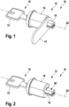
- the Figures 1 to 8 show an embodiment of a locking device 70, designated in its entirety by the reference numeral 10.
- the locking device 70 has a lever cylinder 10 and a key 72.
- the key 72 can have one or more security features 74.
- the lever cylinder 10 serves to lock a door or cover.
- the lever cylinder 10 has a locking cylinder 12 and a lever 14.
- the lever 14 serves to lock a door or cover.
- the locking cylinder 12 has a cylinder housing 16, a cylinder core 18, and a sensor device 50.
- the cylinder core 18 is rotatable relative to the cylinder housing 16 about the rotation axis 20.
- the cylinder core 18 is mounted in the cylinder housing 16 so as to be rotatable about the rotation axis 20.
- the cylinder core 18 has a substantially cylindrical shape. An axial direction, a radial direction, and a circumferential direction are defined according to the cylindrical shape.
- the rotation axis 20 runs parallel to the axial direction.
- the cylinder core 18 is substantially rotationally symmetrical with respect to the rotation axis 20.
- the cylinder core 18 extends in the axial direction from a first core end 26 to a second core end 28.
- the cylinder core 18 further has a keyway 30.
- the keyway 30 extends in the axial direction.
- the keyway 30 is open toward the first core end 26.
- the key 72 can be inserted into the keyway from the first core end 26 in an insertion direction.
- the insertion direction runs parallel to the axial direction.
- the cylinder core 18 further comprises a core groove 32.
- the core groove 32 extends in the circumferential direction from a first core groove end to a second core groove end.
- the first core groove end and the second core groove end are spaced apart from each other in the circumferential direction by an angle of 90°.
- the core groove 32 is open radially outward.
- the Core groove 32 opens towards the cylinder housing 16. The core groove 32 thus forms a recess in the outer surface of the cylinder core 18.
- the cylinder housing 16 has a cylindrical bore 34.
- the cylinder core 18 is arranged in the cylindrical bore 34 and mounted for rotation about the rotation axis 20.
- the diameter of the cylinder core essentially corresponds to the diameter of the cylindrical bore.
- the cylindrical bore extends in the axial direction from a first housing end 36 to a second housing end 38.
- the first core end 26 is arranged in the axial direction at the first housing end 34.
- the second core end 28 is arranged outside the cylinder housing 16.
- the cylinder core 18 extends in the axial direction toward the second core end 28 out of the cylinder housing 16, in particular beyond the second housing end 38.
- the lever 14 is arranged in the axial direction between the second housing end 38 and the second core end 28.
- the cylinder core 18 is rotatable about the rotation axis 20 at least between the first rotation position 22 and the second rotation position 24.
- the cylinder core 18 is rotatably mounted in the cylinder housing 16 about the rotation axis 20 between the first rotation position 22 and the second rotation position 24.
- the first rotation position and the second rotation position are offset from one another by an angle of 90° about the rotation axis.
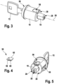
- Fig. 7 the cylinder core 18 is shown in the first rotational position 22.
- Fig. 8 the cylinder core 18 is shown in the second rotational position 24.
- the lever 14 is connected to the cylinder core 18 in a rotationally fixed manner about the rotation axis 20.
- the lever 14 is mounted on the cylinder core 18.
- the cylinder core 18 can have a fastening section 66 for the lever 14.
- the fastening section 66 is arranged in the axial direction between the second housing end 38 and the second core end 28. In the region of the fastening section 66, the shape of the cylinder core 18 deviates from the cylindrical shape.
- the fastening section 66 can have recesses that serve for mounting the lever 14.
- the cylinder housing 16 further has a recess 40.
- the recess 40 serves to accommodate the sensor device 56.
- the sensor device 56 is arranged in the recess 40 and mounted therein.
- the sensor device 56 is integrated into the locking cylinder 12.
- the recess 40 extends in the radial direction up to the cylindrical bore 34.
- the recess 40 is open, in particular, towards the cylindrical bore 34.
- the recess 40 extends up to the cylinder core 18.
- the recess 40 also extends in the radial direction up to an outer side of the cylinder housing 16.
- the recess 40 is thus open both radially inward and radially outward.
- the recess 40 is preferably arranged at the second housing end 38.
- the recess 40 is also open towards the second housing end 40.
- the recess 40 is arranged in the axial direction at the level of the core groove 32.
- the cylinder housing 16 further has a bore 42.
- the bore 42 extends in the radial direction up to the cylindrical bore 34.
- the bore 42 is thus open towards the cylindrical bore 34.
- the bore 42 extends up to the cylinder core 18.
- the bore 42 further extends in the radial direction up to an outer side of the cylinder housing 16.
- the bore 42 is thus open both radially inward and radially outward.
- the bore 42 is arranged in the axial direction at the level of the core groove 32. In particular, the bore 42 is arranged in alignment with the core groove 32.
- the bore 42 is spaced from the recess 40 in the circumferential direction.
- the locking cylinder 12 further comprises a stop pin 52.
- the stop pin 52 is arranged in the bore 42 and, in particular, mounted or fastened therein.
- the stop pin 52 extends from the bore 42 into the core groove 32.
- the stop pin 52 bears against the first core groove end of the core groove 32.
- the stop pin 52 bears against the second core groove end of the core groove 32. In this way, rotation of the cylinder core 18 about the rotational axis 20 is limited to a rotation range between the first rotational position 22 and the second rotational position 24. In the present embodiment, the rotation range is 90°.
- the stop pin 52 is further arranged in the core groove 32 such that the cylinder core 18 cannot be moved axially relative to the cylinder housing 16.
- a width of the core groove 32 in the axial direction can essentially correspond to a width of the stop pin 52 in the axial direction.
- the cylinder core 18 is axially secured by the stop pin 52.
- the locking cylinder 12 can further comprise a locking ring 44 and a cover 46.
- the locking ring 44 can also be called a snap ring.
- the cover 46 serves as a disk or anti-drill disk. It is a freely rotatable core protector.
- the cover 46 is mounted in the cylinder housing 16 via the locking ring 44.
- the locking ring 20 axially secures the cover 46 and allows it to rotate freely about the axis 20.
- the cover 46 is arranged axially at the first core end 26 of the cylinder core 18.
- the cover 46 covers the cylinder core 18 from the outside.
- the cover 46 has a recess that can be arranged in alignment with the keyway 30 and serves as an insertion opening for the key 72.
- the cylinder core 18 and the cover 46 are not directly coupled to each other. They both have the same degree of freedom of rotation around the rotation axis 20. Just as with a security fitting, the recess in the cover 46 through which the key 72 is inserted can be rotated relative to the keyway 30 of the cylinder core 18. Then, the cover 46 must first be aligned with the cylinder core 18 using the key 72 before the key 72 can be fully inserted.
- the locking cylinder 12 may further comprise a closure element 54.
- the closure element 54 may be inserted from the second core end 28 in the axial direction into the cylinder core 18, in particular into the keyway 30, and secured therein.
- the locking cylinder 12 further comprises one or more locking devices 50.
- the locking devices 50 serve to block a rotational movement of the cylinder core 18 relative to the cylinder housing 16 in a locked state of the locking cylinder 12 and to prevent a rotational movement of the cylinder core 18 relative to the cylinder housing 16.
- the cylinder core 18 cannot be rotated about the rotation axis 20.
- the cylinder core 18 can be rotated about the rotation axis 20.
- the locking devices 50 serve to query the security features 74 of the key 72.
- Each security feature 74 can be, for example, a projection, a recess, a movable element, or a specific surface profile.
- Each locking device 50 is assigned to a corresponding security feature 74 of the key 72 and serves to query the corresponding security feature 74.
- Each locking device 50 has a locking position and a release position. In the locking position, a locking device 50 blocks the rotational movement of the cylinder core 18 about the rotation axis 20. In the release position, the locking device 50 allows the rotational movement of the cylinder core 18 about the rotation axis 20.
- each locking device 50 can be configured such that the locking device 50 has the locking position as its basic position. By positively querying the corresponding security feature 74, the locking device can be transferred from the locking position to the release position.
- the locking cylinder 12 is in the locked state. If all locking devices 50 are in the release position, the locking cylinder 12 is in the release state.
- the locking cylinder is thus designed such that the locking cylinder 12 has the locked state as its default state and can only be transferred to the release state upon positive query of all locking devices 50.
- the locking cylinder can be transferred from the locked state to the unlocked state by fully inserting the key 72 into the keyway 30.
- the locking cylinder 12 is therefore constructed such that, when the key 72 is fully inserted, all locking devices 50 positively query the corresponding security features 74 of the key 72.
- the locking safeguards 50 are designed as pin tumblers.
- Each pin tumbler can have a housing pin and a core pin.
- the core pin can be mounted so as to be movable in the radial direction in a corresponding core bore of the cylinder core 18, and the housing pin can be mounted so as to be movable in the housing bore of the cylinder housing 16.
- the locked position either the housing pin extends partially into the core bore or the core pin partially into the housing bore.
- a rotational movement of the cylinder core 18 is blocked by the corresponding pin tumbler.
- the core pin is arranged only in the core bore and the housing pin is only in the housing bore.
- a rotational movement of the cylinder core 18 is not blocked by the corresponding pin tumbler.
- the housing pin can be preloaded radially inward.
- the sensor device 56 is configured to detect a rotational position of the cylinder core 18 or a rotation of the cylinder core 18. For example, the sensor device 56 can detect whether the cylinder core 18 is arranged in the first rotational position 22 or the second rotational position 24. Alternatively or additionally, the sensor device 56 can also detect whether and/or how the cylinder core 18 is rotated between the first rotational position 22 and the second rotational position 24.
- the detected rotational position and/or the detected rotation of the cylinder core 18 can then be used, for example, to control an electrical circuit.
- the sensor device 56 can be configured to control an electrical circuit based on the detected rotation of the cylinder core and/or the detected rotational position of the cylinder core.
- the sensor device 56 can be configured to output a sensor signal to the electrical circuit, wherein the sensor signal contains information regarding the detected rotation of the cylinder core 18 or the detected rotational position of the cylinder core 18.
- the sensor signal can then be evaluated, for example, by means of a control device of the electrical circuit in order to control the electrical circuit accordingly.
- the structure of the sensor device 56 is shown in Fig. 4 shown in detail.
- the arrangement of the sensor device 56 in the recess 40 of the cylinder core 18 is shown in Fig. 5 illustrated.
- the sensor device 56 has a sensor 58 for detecting the rotation or rotational position of the cylinder core 18.
- the sensor device 56 can also have multiple sensors 58.
- the sensor device 56 can have a mechanical sensor and/or a magnetic sensor and/or an inertial sensor and/or a position sensor.
- the senor 58 is designed as a mechanical sensor or position sensor, in particular as a button.
- the sensor has a sensing element 60.
- the sensing element 60 is designed as a tactile flag and serves as the switching element of the sensor 58.
- the sensor 58 is mounted in the recess 40 by means of a mounting plate 62.
- the mounting plate 62 is fastened to the cylinder core 18 in the recess 40 by means of one or more fastening means 64.
- the mounting plate 62 can also be designed as a printed circuit board or circuit card.
- the sensor 58 can then be designed, in particular, as an SMD ("surface-mounted device") component.
- the sensor 58 or the mounting plate 62 can have a socket via which a connecting cable of the electrical circuit can be connected to the sensor.
- the connecting cable can also be connected directly to the sensor.
- two strands of the cable can also be soldered onto the printed circuit board or circuit card.
- the sensor device 56 In particular the sensor 58, is configured to detect or query the position of the core groove 32 relative to the sensor device 56.
- the rotational position or rotation of the cylinder core 18 can be detected from the position of the core groove 32 or a change in the position of the core groove 32.
- the sensing element 60 is used to query or detect the position of the core groove 32.
- the sensing element 60 is mounted for this purpose so that it can move in the radial direction.
- the sensing element 60 is preloaded radially inward in the radial direction, in particular in the direction of the cylinder core 18.
- the sensing element 60 is in the axial Direction at the level of the core groove 32.
- the query element 60 extends into the core groove 32 when the core groove 32 is aligned with the query element 60. If the core groove 32 is not aligned with the query element 60, in particular if the core groove 32 is rotated in the circumferential direction about the rotation axis 20 relative to the query element 60, the query element 60 is pressed radially outward by the cylinder core 18.
- the cylinder core 18 is arranged in the first rotational position 22.
- the core groove 32 is arranged radially aligned with the sensor device 56 and the recess 40.
- the interrogation element 60 is arranged radially aligned with the core groove 32. Due to the preload force, the interrogation element 60 is pressed into the core groove 32 in the first rotational position 22 and thus extends into the core groove 32.
- the cylinder core 18 is arranged in the second rotational position 24.
- the core groove 32 is not arranged radially aligned with the sensor device 56 and the recess 40.
- the interrogation element 60 is not arranged radially aligned with the core groove 32.
- the interrogation element 60 rests against the outer surface of the cylinder core 18 and does not extend into the core groove 32.
- the interrogation element 60 is thus pressed outwards in the radial direction by the cylinder core 18.
- the interrogation element 60 is thus moved radially accordingly.
- the cylinder core 18 can be rotated, in particular, by means of the key 72 when the latter is fully inserted into the key channel 30.
- the sensor 58 designed as a button, can be configured such that it is actuated when the interrogation element 60 is pressed radially outward.
- the button is not actuated in the first rotational position 22 and actuated in the second rotational position.
- a circuit of an electrical circuit can be closed when the button is actuated.
- the interrogation element 60 is pushed radially outward, thus actuating the button. If the cylinder core 18 is rotated to the first rotational position 22 using the key 72 during a closing operation, the interrogation element 60 is pushed radially inward, thus deactivating the button.
- the lever 14 is, in particular, movable between the open position 97 and the closed position 95.
- the lever 14 is mounted on the cylinder core 18 such that the lever 14 is arranged in the closed position 95 when the cylinder core 18 is arranged in the first rotational position 22, and in the open position 97 when the cylinder core 18 is arranged in the second rotational position 24.
- the lever 14 can thus be pivoted between the closed position 95 and the open position 97.
- the door 94 serves to close access to a housing 96 having a housing wall 98.
- the lever cylinder serves to lock the door 94 relative to the housing 96.
- the lever cylinder 10 is mounted on the door 94.
- the door has a bore into which the lever cylinder 10 is inserted and mounted.
- the lever 14 is arranged on an inner side of the door 94.
- the opening for inserting the key into the keyway at the first core end 26 is arranged on an outer side of the door 94.
- the lever 14 In the closed position 95, the lever 14 is arranged such that it engages with the housing wall 98. As a result, the door 94 is locked or closed.
- the housing wall 98 thus serves as a stop element for the lever 14.
- the lever 14 In the open position 97, the lever 14 is arranged such that it does not engage with the housing wall 98. As a result, the door 94 is not locked and can be opened.
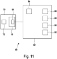
- Fig. 11 shows an embodiment of a system designated in its entirety by the reference numeral 80.
- the system 80 includes the locking device 70 and an electrical circuit 82.
- the system 80 may further include the door 94 and/or the housing 96.
- the electrical circuit 82 may, in particular, be arranged on the door 94 and/or on the housing 96.
- the electrical circuit 82 can be constructed from electrical or electromechanical elements that are combined to form a functional arrangement.
- the electrical circuit 82 can have a control device 84, one or more devices 86, 88, a storage device 90, and/or a safety device 92.
- the devices 86, 88 can be, for example, a lighting device, an actuator, a motor, and/or an acoustic device.
- the lighting device and/or the actuator and/or the acoustic device can be arranged in the housing 96.
- the lighting device can serve to illuminate the interior of the housing 96.
- the actuator can serve to move an object in the housing 96.
- the acoustic device can serve to output an acoustic signal.
- the storage device 90 can be an electrical data storage device.
- the storage device 90 can, in particular, have a storage medium for storing data or information.
- the storage medium can be a volatile or non-volatile memory.
- the safety device 92 can serve to further secure the door 94 or the housing 96.
- the safety device 92 can, for example, be an additional security level, in particular a mechatronic locking box, or an alarm system.
- the electrical circuit 82 is controlled based on the detected rotation or the detected rotational position of the cylinder core 18.
- the electrical circuit 82 can be switched via the sensor device 56, in particular upon actuation of the button.
- information regarding the rotation and/or the rotational position of the cylinder core 18 can be sensed by the sensor device and then transmitted to the electrical circuit 82 for evaluation and corresponding control.
- the sensor device 56 can output a corresponding sensor signal to an electrical circuit 82.
- the sensor signal can, for example, contain information regarding the detected rotation of the cylinder core 18 or the detected rotational position of the cylinder core 18.
- the sensor device 56 can output a sensor signal containing information regarding the second rotational position 24 or information regarding a rotation into the second rotational position 24.
- the sensor device 56 can output a sensor signal containing information regarding the first rotational position 22 or information regarding a rotation into the first rotational position 22.
- the control device 84 serves to control the electrical circuit.
- the control device 84 can control the electrical circuit 82 based on the detected rotation and/or the detected rotational position of the cylinder core 18.
- the control device 84 can detect an actuation of the button and control the electrical circuit 82 accordingly.
- the control device 84 can receive the sensor signal from the sensor device 56 and control the electrical circuit 82 based on the sensor signal.
- the control device 84 is configured to control components of the electrical circuit 82 and to process data.
- the control device 84 can, for example, have various subunits, each of which controls a component and/or processes data.
- the control device 84 can have a control unit that controls devices 86, 88, the memory device 90 and/or the safety device 92.
- the control device 84 can have a data processing unit that is configured to carry out the evaluation of the detected rotation or the detected rotational position of the cylinder core 18, in particular the evaluation of the sensor signal.
- the controller 84 may be connected to or include a non-volatile data memory in which a computer program is stored.
- the controller 84 is a general-purpose computer, such as a commercially available personal computer running Windows® , Linux, or MacOS, and the computer program from the memory includes program code used to implement control of the electrical circuit.
- the controller 84 is a logic circuit, such as a field-programmable gate array (FPGA), an application-specific integrated circuit (ASIC), a microcontroller, or any other suitable programmable logic circuit. Therein, the control may be implemented with the logic circuit. Any suitable programming language or hardware description language may be used to implement the control in the logic circuit, such as C, VHDL, and the like.
- the sensor device 56 or the control device 94 can be configured to control the one or more devices 86, 88 based on the detected rotation or the detected rotational position of the cylinder core 18.
- the devices 86, 88 can be controlled, for example, switched on and off, according to the detected rotational position.
- the lighting or the actuator can be switched on or an acoustic signal can be emitted when the cylinder core is rotated to the second rotational position.
- the lighting or the actuator can be switched off or the output of the acoustic signal can be interrupted.
- the sensor device 56 or the control device 84 can be configured to store information about a detected rotation of the cylinder core 18 in the memory device 90.
- information about an opening process i.e., about a rotation into the second rotational position 24, can be stored in the memory device 90.
- the information regarding the opening process In particular, it may also contain information regarding a time, for example, a date and time, of the opening process.
- the storage device may also simply have a counter that counts the number of opening processes.
- the sensor device 56 or the control device 84 can be configured to control the safety device 92 based on the detected rotation or the detected rotational position of the cylinder core 18, in particular based on the sensor signal.
- the safety device 92 can be activated or deactivated based on the detected rotation or the detected rotational position, in particular during an opening or closing process.
- Fig. 12 shows an embodiment of a method, designated in its entirety by reference numeral 100.
- Method 100 is used to lock and/or open a door or cover using a lever cylinder.
- Method 100 can be performed using lever cylinder 10 or locking device 70 or system 80.
- door 94 can be locked and opened using method 100.
- a first step 102 of the method 100 the key 72 is fully inserted into the key channel 30 in order to transfer the locking cylinder 12 from the locked state to the released state.
- step 104 of the method 100 the key 72 is rotated to rotate the cylinder core 18 between the first rotational position 22 and the second rotational position 24.
- a rotation of the cylinder core 18 and/or a rotational position of the cylinder core 18 is detected by means of the sensor device.
- Step 108 of the method 100 the electrical circuit 82 is controlled on the basis of the detected rotation and/or the detected rotational position of the cylinder core 18. Step 108 can be carried out in particular by means of the sensor device 56 or the control device 84.
- the one or more devices 86, 88 can be controlled based on the detected rotation or the detected rotational position of the cylinder core 18.
- information about a detected rotation of the cylinder core 18 can be stored in the memory device 90.
- the safety device 92 can be controlled based on the detected rotation or the detected rotational position of the cylinder core 18, in particular based on the sensor signal.
Landscapes
- Engineering & Computer Science (AREA)
- Mechanical Engineering (AREA)
- Lock And Its Accessories (AREA)
Applications Claiming Priority (1)
| Application Number | Priority Date | Filing Date | Title |
|---|---|---|---|
| DE102023134803.5A DE102023134803A1 (de) | 2023-12-12 | 2023-12-12 | Hebelzylinder, Schließvorrichtung, System und Verfahren |
Publications (1)
| Publication Number | Publication Date |
|---|---|
| EP4571021A1 true EP4571021A1 (fr) | 2025-06-18 |
Family
ID=93852973
Family Applications (1)
| Application Number | Title | Priority Date | Filing Date |
|---|---|---|---|
| EP24218614.6A Pending EP4571021A1 (fr) | 2023-12-12 | 2024-12-10 | Cylindre à levier, dispositif de fermeture, système et procédé |
Country Status (2)
| Country | Link |
|---|---|
| EP (1) | EP4571021A1 (fr) |
| DE (1) | DE102023134803A1 (fr) |
Citations (6)
| Publication number | Priority date | Publication date | Assignee | Title |
|---|---|---|---|---|
| DE8807728U1 (de) | 1988-06-14 | 1988-07-28 | Siemens AG, 1000 Berlin und 8000 München | Schließeinrichtung für Geräte der Datenverarbeitungstechnik |
| EP0346812A2 (fr) | 1988-06-14 | 1989-12-20 | Siemens Nixdorf Informationssysteme Aktiengesellschaft | Dispositif de fermeture pour des machines telles qu'un ordinateur personnel |
| US5946956A (en) * | 1997-04-25 | 1999-09-07 | Roto Frank Eisenwarenfabrik Ag | Electromechanical lock system |
| DE102005005393A1 (de) * | 2005-02-02 | 2006-08-10 | IKON GmbH Präzisionstechnik | Schließzylinder |
| WO2012035526A1 (fr) * | 2010-09-16 | 2012-03-22 | Saftek Ltd. | Système électronique pour indiquer si une serrure à barillet est verrouillée ou déverrouillée |
| EP3670799B1 (fr) * | 2018-12-20 | 2021-01-27 | Euro-Locks Sicherheitseinrichtungen GmbH | Dispositif de verrouillage |
Family Cites Families (2)
| Publication number | Priority date | Publication date | Assignee | Title |
|---|---|---|---|---|
| US3870842A (en) * | 1973-11-21 | 1975-03-11 | Leonard Lebowitz | Locking device |
| DE19517728C2 (de) * | 1995-05-15 | 1998-12-03 | Keso Gmbh | Schließvorrichtung |
-
2023
- 2023-12-12 DE DE102023134803.5A patent/DE102023134803A1/de active Pending
-
2024
- 2024-12-10 EP EP24218614.6A patent/EP4571021A1/fr active Pending
Patent Citations (6)
| Publication number | Priority date | Publication date | Assignee | Title |
|---|---|---|---|---|
| DE8807728U1 (de) | 1988-06-14 | 1988-07-28 | Siemens AG, 1000 Berlin und 8000 München | Schließeinrichtung für Geräte der Datenverarbeitungstechnik |
| EP0346812A2 (fr) | 1988-06-14 | 1989-12-20 | Siemens Nixdorf Informationssysteme Aktiengesellschaft | Dispositif de fermeture pour des machines telles qu'un ordinateur personnel |
| US5946956A (en) * | 1997-04-25 | 1999-09-07 | Roto Frank Eisenwarenfabrik Ag | Electromechanical lock system |
| DE102005005393A1 (de) * | 2005-02-02 | 2006-08-10 | IKON GmbH Präzisionstechnik | Schließzylinder |
| WO2012035526A1 (fr) * | 2010-09-16 | 2012-03-22 | Saftek Ltd. | Système électronique pour indiquer si une serrure à barillet est verrouillée ou déverrouillée |
| EP3670799B1 (fr) * | 2018-12-20 | 2021-01-27 | Euro-Locks Sicherheitseinrichtungen GmbH | Dispositif de verrouillage |
Also Published As
| Publication number | Publication date |
|---|---|
| DE102023134803A1 (de) | 2025-06-12 |
Similar Documents
| Publication | Publication Date | Title |
|---|---|---|
| DE3880496T2 (de) | Von einer batterie betriebenes tuerschloss sowie verfahren. | |
| EP3591147B1 (fr) | Serrure de deux roues ayant une fonction d'alarme | |
| US8091392B2 (en) | High security lock | |
| DE69312977T2 (de) | Hochsicherheits-Verriegelungsmechanismus | |
| DE3145665C2 (de) | Mittels Permanentmagnetschlüssel betätigbarer Schließzylinder eines Magnetschlosses | |
| DE102008063061A1 (de) | Betätigungsvorrichtung für ein elektronisches Türschloß | |
| DE19747720A1 (de) | Vorrichtung mit einem Schlüssel betätigbaren Schließzylinder und mit einer elektrischen Schalteinrichtung, insbesondere elektronische Wegfahrsperre für ein Kraftfahrzeug | |
| EP3159464B2 (fr) | Systeme de surveillance de fermeture | |
| DE19721202A1 (de) | Einrichtung in einem Schloß, insbesondere eine elektromechanische Verriegelungsanordnung | |
| DE3734399A1 (de) | Schliesseinrichtung mit zusatzfunktionen | |
| EP0542944B1 (fr) | Serrure a ame de cylindre motorisee | |
| DE2251092A1 (de) | Einbruchsicheres zylinderschloss zur verwendung eines schluessels mit doppelter bartform | |
| DE102019107282A1 (de) | Türschlossbetätigungsvorrichtung zum Betätigen eines Türschlosses und Alarmanlage mit einer solchen Türschlossbetätigungsvorrichtung | |
| EP0805905B1 (fr) | Mécanisme de fermeture de porte | |
| EP4571021A1 (fr) | Cylindre à levier, dispositif de fermeture, système et procédé | |
| DE4422094C2 (de) | Schloß für Türen | |
| DE20320720U1 (de) | Schließzylinder | |
| EP2840205B1 (fr) | Dispositif de fermeture | |
| EP3095934A1 (fr) | Dispositif de détection d'une position de verrou | |
| DE202016005817U1 (de) | Elektromechanischer Verschluss | |
| EP3627458B1 (fr) | Élément de fermeture et coffre-fort tubulaire doté d'un tel élément de fermeture | |
| DE3823276A1 (de) | Diebstahlschutzvorrichtung | |
| EP0402442A1 (fr) | Systeme de verrouillage et procede correspondant | |
| EP3511490B1 (fr) | Poignée pour une fenêtre ou une porte et système d'installation d'alarme doté de plusieurs de poignées | |
| DE19518491C2 (de) | Anordnung aus zwei Schließzylindern für abzusichernde Zugangsbereiche |
Legal Events
| Date | Code | Title | Description |
|---|---|---|---|
| PUAI | Public reference made under article 153(3) epc to a published international application that has entered the european phase |
Free format text: ORIGINAL CODE: 0009012 |
|
| STAA | Information on the status of an ep patent application or granted ep patent |
Free format text: STATUS: THE APPLICATION HAS BEEN PUBLISHED |
|
| AK | Designated contracting states |
Kind code of ref document: A1 Designated state(s): AL AT BE BG CH CY CZ DE DK EE ES FI FR GB GR HR HU IE IS IT LI LT LU LV MC ME MK MT NL NO PL PT RO RS SE SI SK SM TR |
|
| STAA | Information on the status of an ep patent application or granted ep patent |
Free format text: STATUS: REQUEST FOR EXAMINATION WAS MADE |
|
| 17P | Request for examination filed |
Effective date: 20251210 |