EP4571074A1 - Gondel für turbopropellermotoren - Google Patents
Gondel für turbopropellermotoren Download PDFInfo
- Publication number
- EP4571074A1 EP4571074A1 EP23383295.5A EP23383295A EP4571074A1 EP 4571074 A1 EP4571074 A1 EP 4571074A1 EP 23383295 A EP23383295 A EP 23383295A EP 4571074 A1 EP4571074 A1 EP 4571074A1
- Authority
- EP
- European Patent Office
- Prior art keywords
- nacelle
- air intake
- turbo
- channel
- compressor
- Prior art date
- Legal status (The legal status is an assumption and is not a legal conclusion. Google has not performed a legal analysis and makes no representation as to the accuracy of the status listed.)
- Pending
Links
Images



Classifications
-
- F—MECHANICAL ENGINEERING; LIGHTING; HEATING; WEAPONS; BLASTING
- F02—COMBUSTION ENGINES; HOT-GAS OR COMBUSTION-PRODUCT ENGINE PLANTS
- F02C—GAS-TURBINE PLANTS; AIR INTAKES FOR JET-PROPULSION PLANTS; CONTROLLING FUEL SUPPLY IN AIR-BREATHING JET-PROPULSION PLANTS
- F02C7/00—Features, components parts, details or accessories, not provided for in, or of interest apart form groups F02C1/00 - F02C6/00; Air intakes for jet-propulsion plants
- F02C7/04—Air intakes for gas-turbine plants or jet-propulsion plants
-
- B—PERFORMING OPERATIONS; TRANSPORTING
- B64—AIRCRAFT; AVIATION; COSMONAUTICS
- B64D—EQUIPMENT FOR FITTING IN OR TO AIRCRAFT; FLIGHT SUITS; PARACHUTES; ARRANGEMENT OR MOUNTING OF POWER PLANTS OR PROPULSION TRANSMISSIONS IN AIRCRAFT
- B64D29/00—Power-plant nacelles, fairings or cowlings
-
- F—MECHANICAL ENGINEERING; LIGHTING; HEATING; WEAPONS; BLASTING
- F02—COMBUSTION ENGINES; HOT-GAS OR COMBUSTION-PRODUCT ENGINE PLANTS
- F02C—GAS-TURBINE PLANTS; AIR INTAKES FOR JET-PROPULSION PLANTS; CONTROLLING FUEL SUPPLY IN AIR-BREATHING JET-PROPULSION PLANTS
- F02C6/00—Plural gas-turbine plants; Combinations of gas-turbine plants with other apparatus; Adaptations of gas-turbine plants for special use
- F02C6/20—Adaptations of gas-turbine plants for driving vehicles
- F02C6/206—Adaptations of gas-turbine plants for driving vehicles the vehicles being airscrew driven
-
- B—PERFORMING OPERATIONS; TRANSPORTING
- B64—AIRCRAFT; AVIATION; COSMONAUTICS
- B64D—EQUIPMENT FOR FITTING IN OR TO AIRCRAFT; FLIGHT SUITS; PARACHUTES; ARRANGEMENT OR MOUNTING OF POWER PLANTS OR PROPULSION TRANSMISSIONS IN AIRCRAFT
- B64D27/00—Arrangement or mounting of power plants in aircraft; Aircraft characterised by the type or position of power plants
- B64D27/02—Aircraft characterised by the type or position of power plants
- B64D27/10—Aircraft characterised by the type or position of power plants of gas-turbine type
-
- F—MECHANICAL ENGINEERING; LIGHTING; HEATING; WEAPONS; BLASTING
- F05—INDEXING SCHEMES RELATING TO ENGINES OR PUMPS IN VARIOUS SUBCLASSES OF CLASSES F01-F04
- F05D—INDEXING SCHEME FOR ASPECTS RELATING TO NON-POSITIVE-DISPLACEMENT MACHINES OR ENGINES, GAS-TURBINES OR JET-PROPULSION PLANTS
- F05D2220/00—Application
- F05D2220/30—Application in turbines
- F05D2220/32—Application in turbines in gas turbines
- F05D2220/325—Application in turbines in gas turbines to drive unshrouded, high solidity propeller
Definitions
- the present invention belongs to the field of aircraft engines, and particularly, it belongs to the nacelle architecture for turbo-propeller engines. More particularly, an object of the present invention is to provide an improved engine air intake of a nacelle for a turbo-propeller engine of an aircraft.
- Existing aircrafts typically include one or more primary engines for propulsion, which may vary depending on the intended flight regime of the aircraft.
- turbo-propeller or turboprop engines that is, a variant of an aeronautical engine that has been optimized to drive a propeller, are designed to flight at subsonic speed.
- turboprop engines are of special interest at flight regime of lower flight speed, at which they become very efficient in terms of burning less fuel and requiring significantly less runway for takeoff and landing in comparison with a turbojet or turbofan powered aircraft of the same size.
- turbo-propeller engine air intakes The classical concept for turbo-propeller engine air intakes is composed by an inlet duct oriented stream-wise capturing the air from that particular direction.
- the inlet duct directs the airflow in the optimum conditions towards the engine compressor airflow inlet, feeding the turbomachinery.
- the air intake is usually connected directly to the compressor airflow inlet but some engines also require an additional compartment located in-between the air intake and the compressor airflow inlet.
- the present invention provides a nacelle for a turbo-propeller engine of an aircraft according to claim 1 and an aircraft according to claim 13.
- preferred embodiments of the invention are defined.
- the present invention provides a nacelle for a turbo-propeller engine of an aircraft, the nacelle comprising:
- the present invention applies to an improved nacelle architecture for a turbo-propeller engine, in particular, to an improved air intake configuration which allows feeding the compressor section of the turbo-propeller engine. Also, the present invention provides a lighter nacelle with respect to the nacelle architecture known in the art by, for example, reducing the cross-section area of the nacelle, reducing the wet area of said nacelle and increasing the drag.
- the present invention allows, for example, to avoid implementing an additional anti-icing system, which are known as high demanding in energy, and results in an additional reduction of the weight of the nacelle but also involves higher performances due to the overall energy saving.
- nacelles of the state of the art which normally include anti-ice systems, comprise a set of ducts and normally require bleed air to function at its optimal capacity. Nevertheless, said bleed air deteriorates the turbo-propeller engine performances because of the air extraction necessary when the anti-ice system is enabled. Additionally, the anti-ice system also influences the safety in-flight because icing conditions shall be avoided in case of loss of the overall aircraft system. Therefore, since the present nacelle configuration does not require anti-ice system and, thus, reduces energy consumption of an aircraft. Additionally, the present nacelle configuration also provides a solution for improving overall in-flight conditions for an aircraft.
- the nacelle of the first inventive aspect provides a nacelle comprising a front section, a middle section and a rear section. All these sections of the nacelle are arranged one after the other and coaxially with respect to a longitudinal axis X-X'. Specifically, this longitudinal axis X-X' corresponds to the centerline of the turbo-propeller engine when installed in the nacelle.
- the middle section of the nacelle is the part of the nacelle corresponding at least to the location of the compressor section of the engine.
- Said middle section comprises at least one air intake located on the outermost part of the middle section of the nacelle and the at least one air intake defines a channel inlet and a channel outlet.
- the channel inlet of the at least one air intake is disposed on the outermost part of the middle section of the nacelle and the channel outlet of each air intake is disposed on the inside of the middle section of the nacelle. That is, the at least one air intake provide a fluidic communication between the outside of the nacelle and the compressor section of the turbo-propeller engine when installed in the nacelle.
- the at least one air intake is configured for capturing the airflow from the outside.
- the channel inlet and the channel outlet forms a path or a conduct which helps channeling the airflow captured from the outside of the nacelle towards the compressor section of the turbo-propeller engine.
- the length of the channel defined by the channel inlet and the channel outlet is equal to the thickness of the nacelle.
- the length of the channel defined by the channel inlet and the channel outlet is greater that the thickness of the nacelle.
- the channel defined by the air intake protrudes towards the inside of the nacelle, i.e. goes beyond the thickness of the nacelle towards the inside of the nacelle.
- Common turbo-propeller engines comprise a single air intake, a reduction gearbox, a compressor, a combustion chamber, a turbine and a propelling nozzle.
- Airflow enters the air intake of the nacelle and is compressed by the compressor in order to increase the pressure and temperature of the airflow. Then fuel is further added to the compressed air and flowed towards the combustion chamber where the mixture of air and fuel is ignited.
- the at least one air intake provides direct feeding of airflow to the compressor section of the turbo-propeller engine, in particular, as close as possible to the compressor airflow inlet of the compressor. That is, thanks to the disposition and location of the at least one air intake at the middle section of the nacelle, the proximity between the at least one air intake and the compressor section contributes to provide a solution with advantages and benefits as the ones above mentioned.
- the nacelle architecture of the present invention helps feeding airflow from the outside of the nacelle to the compressor section of the turbo-propeller engine. That is, the airflow captured from the outside is directly discharged inside the compressor section.
- the at least one air intake is disposed flush with respect to the outermost of the middle section of the nacelle which helps providing an aerodynamic profile to the overall nacelle and helps with the drag increase allowed by the improved architecture of the present invention.
- the solution provided by the present invention helps saving space inside the nacelle with respect to the nacelle know in the art, which also make possible an optimization of the cowls size, resulting in saving additional drag, cost and more weight.
- the at least one air intake is distributed coaxially to the longitudinal axis X-X' along the middle section.
- the nacelle comprises a top portion and a bottom portion, and wherein the at least one air intake is distributed along the top portion of the nacelle or the bottom portion of the nacelle or along the top and bottom portion of the nacelle.
- the top portion of the nacelle is the portion located on the upper part of the nacelle with respect to a horizontal plane containing the longitudinal axis X-X'.
- the bottom portion of the nacelle is the portion located on the lower part of the nacelle with respect to a horizontal plane containing the longitudinal axis X-X'.
- the at least one air intake is a single air intake as an elongated inlet or slot with a substantially rectangular form, which extends along a portion of the middle section. In an embodiment, this single air intake is circumferentially extended relative to the longitudinal axis X-X'.
- the nacelle comprises a plurality of air intakes.
- the single air intake or the plurality of air intakes of the nacelle of the present invention are placed circumferentially and provokes a radial airflow which results in a more homogeneous and further improved distribution of said airflow inside the compressor section.
- the distortion levels of the airflow provided at the compressor airflow inlet of the compressor decrease and are more effectively managed.
- the nacelle comprises a first air intake elongated and with a substantially rectangular form, this first air intake being extended along a portion of the middle section, preferably along a top portion of the nacelle.
- the nacelle further comprises one or more second air intakes smaller than the first air intake, these second air intakes being located on a portion of the middle section, preferably on a bottom portion of the nacelle.
- the plurality of air intakes is distributed in one array coaxially to the longitudinal axis X-X' along the middle section of the nacelle.
- the plurality of air intakes is distributed in a plurality of circle arrays coaxially to the longitudinal axis X-X' along the middle section.
- one circle array of air intakes is symmetrically distributed with respect to the longitudinal axis and along the circumference of the middle section of the nacelle.
- the plurality of air intakes is circumferentially distributed along the middle section in an alternate Z-pattern.
- the provision of air intake distributed in an alternate Z-pattern means that there are two group of air intakes coaxially to the longitudinal axis X-X'. That is, there is a first plurality of air intakes and a second plurality of air intakes, so that the first plurality of air intakes is closer to the front section of the nacelle while the second plurality of air intakes is closer to the rear section of the nacelle. In addition, comparing these first and second plurality of air intakes, the air intakes of the first plurality are not aligned with the air intakes of the second plurality according to the direction provided by longitudinal axis X-X'.
- the plurality of air intakes are distributed in an alternate Z-pattern when the plurality of air intakes is distributed in a plurality of circle arrays coaxially to the longitudinal axis X-X' along the middle section.
- one air intake of a first array is shifted with respect to the second array and is located in between two successive air intakes of said second array which results in the formation of the alternate Z-pattern.
- the air intake of the first array is equidistant from the two successive air intakes of said second array.
- one air intake of the second array is equidistant from two successive air intakes of the first array and shifted with respect to the first array.
- the plurality of air intakes are distributed equidistant from each other along the middle section.
- this specific distribution of the air intakes ensures a homogeneous injection of the airflow captured at the channel inlet of the air intakes.
- the channel inlet of the at least one air intake is triangular-shaped or rectangular-shaped.
- the area of the channel inlet is greater than the area of the channel outlet.
- the conduct displayed between the channel inlet and the channel outlet as a substantially funnel shape which provides an acceleration of the airflow previous to the injection of said airflow inside the compressor section.
- the at least one air intake comprises an upper wall extending from the channel inlet to the channel outlet and the upper wall is substantially U-shaped.
- the upper wall is substantially U-shaped, also called lip, thanks to the presence of a protrusion emerging at the edge of the channel inlet and further connecting to the channel outlet. Furthermore, the protrusion defined by the U-shaped upper wall substantially extends towards the opposite wall of the at least one air intake and helps reducing the section area of the conduct displayed inside the at least one air intake until reaching the smaller section area of the conduct which is the channel outlet area. That is, this protrusion defined by the U-shaped upper wall projects to the inside of the channel of each air intake.
- a U-shaped upper wall increases the acceleration and decreases pressure losses of the airflow captured at the channel inlet.
- the at least one air intake further comprises a lower wall, opposite to the upper wall, and the lower wall is substantially curved.
- the lower wall of the at least one air intake is substantially curved in order to provide a more pronounced aerodynamic profile to the overall air intake.
- the upper wall is substantially U-shaped and the lower wall is substantially curved.
- the at least one air intake having both of the previously mentioned features ensures an increase acceleration of the captured airflow and optimal conditions for injected said airflow into the compressor section.
- the at least one air intakes is projected inwardly towards the inside of the middle section.
- this configuration helps directing the airflow towards the compressor section in an optimal manner, that is, by enabling the airflow to be supplied as directly and as close as possible to the compressor section so that air loss is diminished and as much quantity of captured airflow is transferred from the channel inlet to the compression inlet of the compressor section of the engine.
- the nacelle is substantially elliptical-shaped.
- the nacelle is substantially elliptical-shaped so that the nacelle has an aerodynamic profile.
- the present invention provides an aircraft comprising at least one turbo-propeller engine partially covered by a nacelle according to any one of the preceding claims, wherein the turbo-propeller engine comprises a compressor section comprising a compressor airflow inlet.
- the invention also has other structural benefits such as reducing the weight of the overall aircraft structure which has to support the nacelle, for example the pylon.
- the pylon structure takes advantage of the nacelle architecture of the first inventive aspect of the invention since it carries all the loads to the fuselage or wing depending on where the engines are attached.
- the at least one air intake is directly connected to the compressor airflow inlet.
- the turbo-propeller engine further comprises a plenum compartment located between the channel outlets of the at least one air intake and the compressor airflow inlet, so that the channel outlet lead to the plenum compartment.
- the plenum compartment is located between the channel outlet of the at least one air intake and the compressor airflow inlet so that the airflow captured at the channel inlet of the at least one air intake is contained in an enclosed chamber.
- This plenum compartment is configured for maintaining the airflow entered at a specific pressure which is higher than the ambient pressure outside the nacelle and before injection of said airflow inside the compressor.
- the plenum has an annular shape distributed around the compressor from which said compressor collect the airflow previously captured at the channel inlet and stored inside the plenum at a specific pressure.
- the plenum compartment helps stabilizing the pressure of the captured airflow and ensures an even distribution of said airflow inside the compressor section and before injection into the compressor by means of the compressor airflow inlet.
- Figures 1A-1B show a schematic view of a nacelle (1) for a turbo-propeller engine of an aircraft comprising a front section (2), a middle section (3) and a rear section (4). These sections (2, 3, 4) of the nacelle (1) are arranged coaxially to a longitudinal axis X-X'. In an embodiment, this longitudinal axis X-X' coincides with the centerline of the turbo-propeller engine when installed in the nacelle (2).
- the middle section (3) of the nacelle comprises a plurality of air intakes (5) so that the air intakes (5) are coincident to a compressor section (12) of the turbo-propeller engine (11) when installed in the nacelle (1) (as shown in figure 2 ).
- the plurality of air intakes (5) is distributed coaxially to the longitudinal axis X-X' along the middle section (3) of the nacelle (1). Also, the nacelle (1) shows a single array of air intakes (5) arranged at the middle section (3) of said nacelle (1).
- the nacelle (1) comprises at least two arrays of air intakes (5) arranged along the middle section and coaxially to the longitudinal axis X-X'.
- the plurality of air intakes (5) comprises at least two arrays of air intakes (5) and is circumferentially distributed along the middle section (3) in an alternate Z-pattern.
- each air intake (5) defines a channel comprising a channel inlet (5.1) and a channel outlet (not shown), the channel inlet (5.1) being on the outermost part (3.1) of the middle section (3) and the channel outlet (not shown) being on the inside (3.2) of the middle section (3).
- This plurality of air intakes (5) is configured for capturing and channeling airflow from the outside of the nacelle (1) towards the compressor section of the turbo-propeller engine (11) inside the nacelle (1).
- the nacelle (1) of figure 1A shows that the air intakes (5) are distributed equidistant from each other along the middle section (3).
- the channel inlets (5.1) of the plurality of air intakes (5) are substantially rectangular-shaped.
- the channel inlets (5.1) of the plurality of air intakes (5) are triangular-shaped.
- the nacelle (1) comprises a top portion and a bottom portion and one air intake (5) located on the top portion of the nacelle and coincident to a compressor section (12) of the turbo-propeller engine (11) when installed in the nacelle (1).
- the air intake (5) shown in figure 1B is distributed along the top portion of the nacelle (1) as an elongated slot with a substantially rectangular form and being circumferentially extended relative to the longitudinal axis X-X'.
- the length of the channel defined by the at least one air intake (5) is equal to the thickness of the nacelle (1).
- the at least one air intake (5) is a hole.
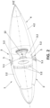
- Figure 2 shows a cross-section view along the longitudinal axis X-X' of an embodiment of the nacelle (1) of the invention shown in figure 1A .
- the nacelle (1) comprises a plurality of air intakes (5) which are projected inwardly towards the inside (3.2) of the middle section (3) of the nacelle (1).
- the channel outlets (5.2) are directed towards the compressor section (12) so that the airflow injection is further optimized.
- the nacelle (1) is substantially elliptical-shaped which provide an aerodynamic profile to said nacelle (1) and an increased airflow intake while in-flight.
- FIG. 3 shows a detailed schematic view of an air intake (5), said air intake (5) is one embodiment of the plurality of air intake (5) which can be implemented to the nacelle (1) of the present invention.
- the channel inlet (5.1) of the at least one air intake (5) is substantially rectangular-shaped.
- the channel outlet (5.2) of the at least one of air intake (5) is substantially rectangular-shaped.
- both the channel inlet (5.1) and the channel outlet (5.2) of the at least one air intake (5) are substantially rectangular-shaped.
- Figure 3 depicts the conduct displayed between the channel inlet (5.1) and the channel outlet (5.2) in one air intake (5).
- Said conduct displayed between the channel inlet (5.1) and the channel outlet (5.2) is substantially funnel-shaped which provides an acceleration of the airflow previous to the injection of said airflow inside the compressor section (12).
- the area of the channel inlet (5.1) is greater than the area of the channel outlet (5.2). Said reduction of the area from channel inlet (5.1) to the channel outlet (5.2) provides the funnel shape to the conduct displayed between said channel inlet (5.1) and said channel outlet (5.2).
- the air intake (5) has an upper wall (5.3) and a lower wall (5.4), opposite to the upper wall (5.3).
- the upper wall (5.3) extends from the channel inlet (5.1) to the channel outlet (5.2) and is substantially U-shaped.
- the protrusion resulting from the U-shaped upper wall (5.3) is located close to the channel inlet (5.1) which provokes an abrupt reduction of the area when the airflow is captured at the channel inlet (5.1) and said airflow enters in contact with the U-shaped upper wall (5.3).
- the U-shaped upper wall (5.3) ensures an acceleration of the airflow captured at the channel inlet (5.1) so that said airflow is projected towards the channel outlet (5.2) and further towards the compressor section (12) of the turbo-propeller engine (11) when installed in the nacelle (1).
- the lower wall (5.4) of the air intake (5) is substantially curved.
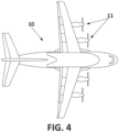
- Figure 4 depicts and embodiment of an aircraft (10) comprising turbo-propeller engines (11) partially covered by a nacelle (1) of the present invention according to any embodiment previously depicted.
- the turbo-propeller engine (11) comprises a compressor section (not shown) and said compressor section further comprises a compressor airflow inlet.
- the at least one air intake (5) of the nacelle (1) is directly connected to the compressor airflow inlet in order to optimize and reduces losses of captured airflow at the channel inlet (5.1) of the at least one air intake (5).
- the turbo-propeller engine (11) further comprises a plenum compartment located between the channel outlets (5.2) of the at least one air intake (5) and the compressor airflow inlet of the compressor section (12), so that the channel outlets (5.2) lead to the plenum compartment.
- the plenum compartment between the at least one air intake (5), more particularly downstream the channel outlets (5.2), and the compressor airflow inlet, the airflow captured at the channel inlet (5.1) of the at least one air intake (5) is contained in the plenum compartment.
- This plenum compartment is configured for maintaining the captured airflow at a specific pressure which is higher than the ambient pressure outside of the nacelle (1) and before injection of said airflow inside the compressor. Additionally, this plenum compartment helps stabilizing the pressure of the captured airflow and ensures an even distribution of said airflow inside the compressor section (12) and before injection into the compressor by means of the compressor airflow inlet.
Landscapes
- Engineering & Computer Science (AREA)
- Chemical & Material Sciences (AREA)
- Combustion & Propulsion (AREA)
- Mechanical Engineering (AREA)
- General Engineering & Computer Science (AREA)
- Aviation & Aerospace Engineering (AREA)
- Structures Of Non-Positive Displacement Pumps (AREA)
Priority Applications (1)
| Application Number | Priority Date | Filing Date | Title |
|---|---|---|---|
| EP23383295.5A EP4571074A1 (de) | 2023-12-14 | 2023-12-14 | Gondel für turbopropellermotoren |
Applications Claiming Priority (1)
| Application Number | Priority Date | Filing Date | Title |
|---|---|---|---|
| EP23383295.5A EP4571074A1 (de) | 2023-12-14 | 2023-12-14 | Gondel für turbopropellermotoren |
Publications (1)
| Publication Number | Publication Date |
|---|---|
| EP4571074A1 true EP4571074A1 (de) | 2025-06-18 |
Family
ID=89223218
Family Applications (1)
| Application Number | Title | Priority Date | Filing Date |
|---|---|---|---|
| EP23383295.5A Pending EP4571074A1 (de) | 2023-12-14 | 2023-12-14 | Gondel für turbopropellermotoren |
Country Status (1)
| Country | Link |
|---|---|
| EP (1) | EP4571074A1 (de) |
Citations (4)
| Publication number | Priority date | Publication date | Assignee | Title |
|---|---|---|---|---|
| FR966975A (fr) * | 1948-05-21 | 1950-10-23 | Snecma | Buse d'entrée d'air pour appareils moteurs à turbine à gaz |
| GB1410160A (en) * | 1973-04-12 | 1975-10-15 | Dornier Gmbh | Aircraft engine nacelle |
| US20090314004A1 (en) * | 2008-06-20 | 2009-12-24 | Rolls-Royce Deutschland Ltd & Co Kg | Turboprop engine with an apparatus for the generation of a cooling airflow |
| US11572827B1 (en) * | 2021-10-15 | 2023-02-07 | General Electric Company | Unducted propulsion system |
-
2023
- 2023-12-14 EP EP23383295.5A patent/EP4571074A1/de active Pending
Patent Citations (4)
| Publication number | Priority date | Publication date | Assignee | Title |
|---|---|---|---|---|
| FR966975A (fr) * | 1948-05-21 | 1950-10-23 | Snecma | Buse d'entrée d'air pour appareils moteurs à turbine à gaz |
| GB1410160A (en) * | 1973-04-12 | 1975-10-15 | Dornier Gmbh | Aircraft engine nacelle |
| US20090314004A1 (en) * | 2008-06-20 | 2009-12-24 | Rolls-Royce Deutschland Ltd & Co Kg | Turboprop engine with an apparatus for the generation of a cooling airflow |
| US11572827B1 (en) * | 2021-10-15 | 2023-02-07 | General Electric Company | Unducted propulsion system |
Similar Documents
| Publication | Publication Date | Title |
|---|---|---|
| US4466587A (en) | Nacelle installation | |
| CN107521705B (zh) | 用于包括具有边界层吸入推进的发动机的飞行器的组件 | |
| US7162859B2 (en) | Variable cycle propulsion system with gas tapping for a supersonic airplane, and a method of operation | |
| US7905449B2 (en) | Multi-engine aircraft | |
| US10435163B2 (en) | Aircraft propelled by a turbojet engine with contrarotating fans | |
| US8210798B2 (en) | Cooled pusher propeller system | |
| EP1918199B1 (de) | Auslegung eines Flugzeugs | |
| US10967980B2 (en) | Turbine engine propelled airplane having an acoustic baffle | |
| EP2346736B1 (de) | Integrierte einlassausführung | |
| US20080010969A1 (en) | Gas turbine engine and method of operating same | |
| EP2685065B1 (de) | Propellerluftstrahltriebwerk | |
| CA2598304A1 (en) | Fan exhaust nozzle for turbofan engine | |
| US7850116B2 (en) | Ducted open rotor apparatus and method | |
| US9938901B2 (en) | Attachment pylon for a turbine engine | |
| US20180208322A1 (en) | Aircraft comprising a propulsion assembly including a fan on the rear of the fuselage | |
| US9051057B2 (en) | Aircraft air inlet diverter assemblies with improved aerodynamic characteristics | |
| US20140260182A1 (en) | Free stream intake for reverse core engine | |
| US4696159A (en) | Gas turbine outlet arrangement | |
| US6926232B2 (en) | Variable cycle propulsion system with compressed air tapping for a supersonic airplane | |
| RU2430256C2 (ru) | Реактивная система двухконтурного турбореактивного двигателя | |
| EP3778402B1 (de) | Schub-turboprop-triebwerksinstallation | |
| US4070827A (en) | Method and apparatus for limiting ingestion of debris into the inlet of a gas turbine engine | |
| EP4571074A1 (de) | Gondel für turbopropellermotoren | |
| EP3372507B1 (de) | Lufteinlassanordnung mit horizontaler tür für ein flugzeughilfstriebwerk | |
| EP3150807B1 (de) | Hinterkantenkernabschnittentlüftung für ein flugzeugtriebwerk |
Legal Events
| Date | Code | Title | Description |
|---|---|---|---|
| PUAI | Public reference made under article 153(3) epc to a published international application that has entered the european phase |
Free format text: ORIGINAL CODE: 0009012 |
|
| STAA | Information on the status of an ep patent application or granted ep patent |
Free format text: STATUS: THE APPLICATION HAS BEEN PUBLISHED |
|
| AK | Designated contracting states |
Kind code of ref document: A1 Designated state(s): AL AT BE BG CH CY CZ DE DK EE ES FI FR GB GR HR HU IE IS IT LI LT LU LV MC ME MK MT NL NO PL PT RO RS SE SI SK SM TR |
|
| STAA | Information on the status of an ep patent application or granted ep patent |
Free format text: STATUS: REQUEST FOR EXAMINATION WAS MADE |
|
| 17P | Request for examination filed |
Effective date: 20251209 |